When the CNC machine is finished, it will of course be controlled by a computer. But during development, it’ll be handy to test it with other controls, like joysticks. I had in mind to use analog joysticks, so I could control motor speed as well as direction.
Unfortunately, I couldn’t find the analog joystick element that I bought from All Electronics. (That this happened something like nineteen years ago may have a little to do with why I can’t find it right now.) Fortunately, a poll of my friends for an analog joystick I could borrow yielded this game controller that Jeremy had already brought me in a batch of electronics junk:
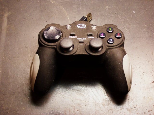
In his own words:
Didn’t like it because it was crappy. The retractable cord (while an OK idea) was too short and stiff. Its real downfall was that the buttons were sticky. They wouldn’t pop back up immediately when pressed so rapid tapping was impossible. More frustrating than useful.
So, perfect for me to butcher for my own purposes.
Inside the Game Controller
My first thought was to extract the analog joystick elements, so I opened the case and dug in.

Here you can see all the guts that make it work. The upper half of the picture is the bottom side of the case, with the retractable USB cable recessed under the PCB, and wipers on the PCB to make contact as it spins.
In the handles near the bottom of the picture are small motors with eccentric weights for “force feedback,” and directly above them at the center of the picture are the pushbuttons on the forward edge. The tan PCB has contacts for the pushbuttons, LEDs, and pseudo-joysticks on the top face; and the green PCB is the brains of the outfit.
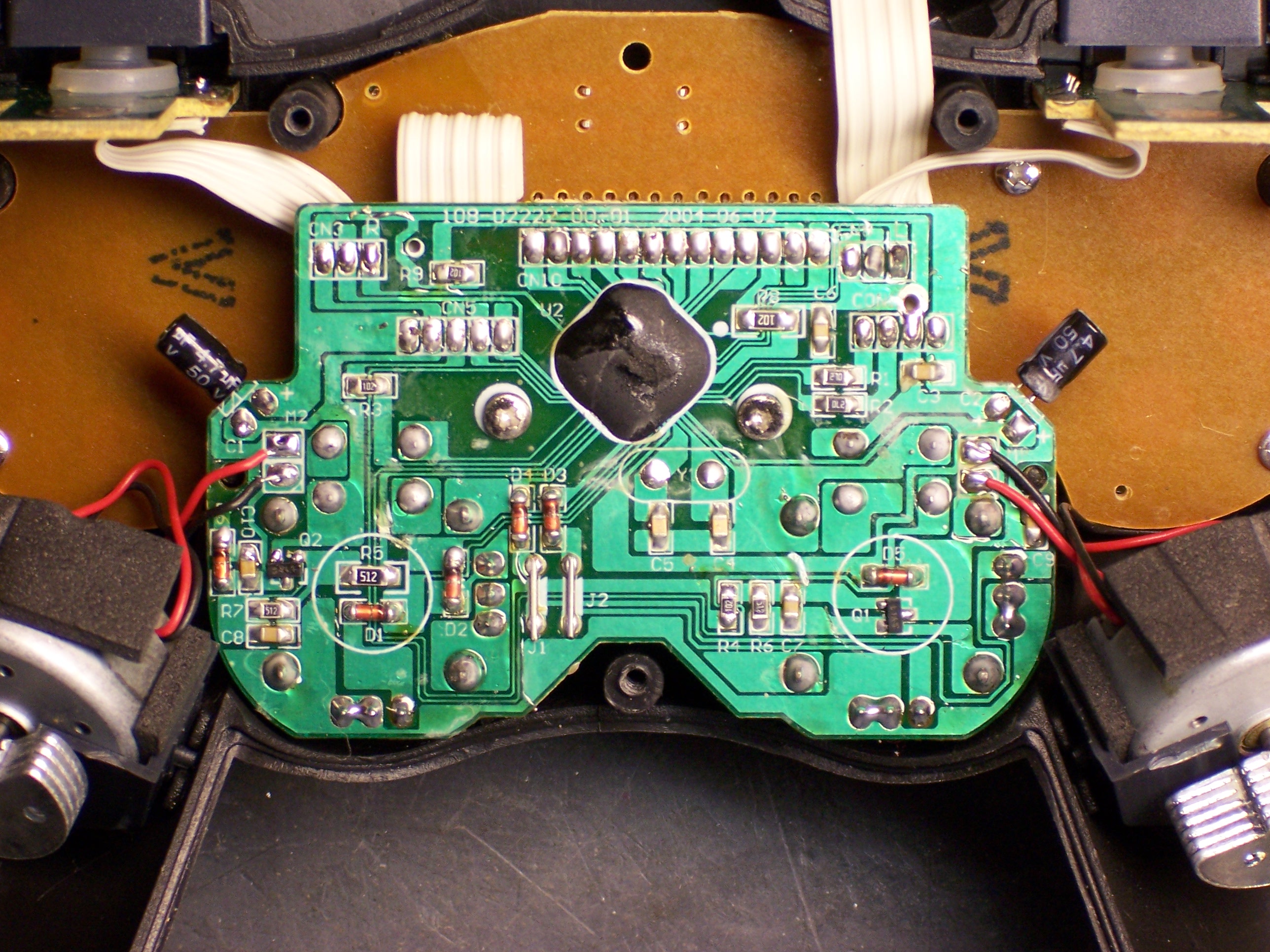
The main board holds the analog joysticks (the solder pads surrounding the silk-screened circles in the lower left and right) and the USB interface (in the black blob).
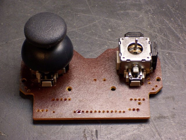
Flipping the main board makes it easy to see how joysticks work. Each is a clever cage with a gimbal mechanism for the stick, connecting to two potentiometers (visible above and to the right of the right stick). These joysticks also have pushbutton action (like clicking the scrolly-wheel on a mouse), so there’s a stick coming out the lower side to a switch housing.
I had actually completely desoldered one of the joysticks when I stopped to think about how I was going to mount them — loose, to a board, what? How about . . . in a game controller case. Duh.
Rewiring
So I soldered the joystick back in and started to look at the circuit. The USB interface was useless to me since I wanted direct access to the analog controls, but I could still use the board as a carrier for the components.
The controller had the potentiometers wired as variable resistors (the wiper tied to one leg, probably for the blob to measure resistance with an RC timer), but I wanted potentiometers so I could measure voltage with an A/D converter on my microcontroller. So the first order of business was cutting traces.
I used a knife to cut through the traces tying the potentiometer wipers to the legs, and the continuity meter to makes sure I’d cut thoroughly enough. Then I identified which direction I wanted to be 0V and which 5V (moving the joystick to the upper right should deliver 5V on each axis), labelled potentiometer terminals with + and -, and started jumpering together pads that hadn’t previously been connected, to distribute power and ground to all the potentiometers.
And that’s how far I got in May, when I last worked on it. I picked it up again this weekend and finished the job.
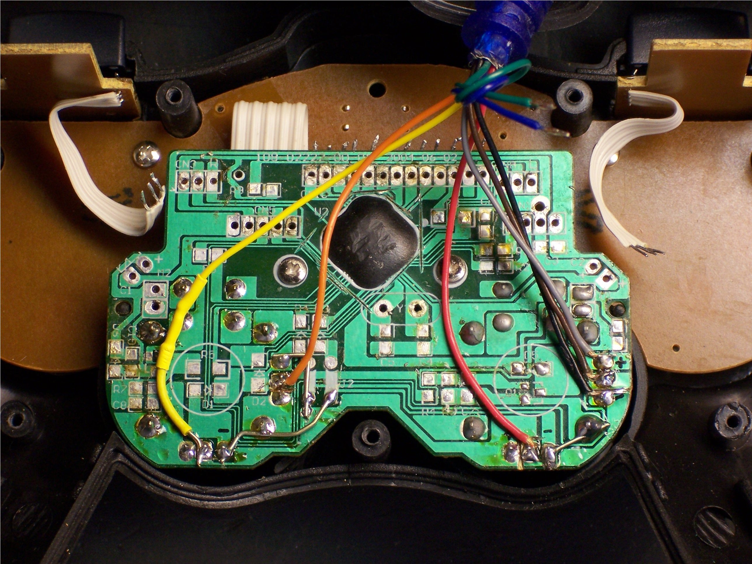
I severed all the connections around the processor blob, since I didn’t need it and didn’t want it getting confused by the new arrangements. And I soldered on wires from a supple new cable Joel gave me (salvaged from who-knows-what). I provide 5V and ground on the grey and black wires, connected joysticks on brown-red-orange-yellow, and have blue and green left over for pushbuttons when I figure out which ones I want to use.
On the loose end, I soldered a header pin to each wire, to fit nicely into prototyping sockets, and heatshrunk each solder joint. I also heatshrunk logical pairs of wires together, to make it easy to remember which wires go together to a potentiometer. You can see that end in my previous post on the Arduino.
I made one mistake, which I had to go back in and correct: I wasn’t thinking straight about which potentiometer was the X axis and which was the Y. The one across the bottom, of course, is the X axis, and the one on the side the Y — but that’s not how I wired it. I swapped the brown and red and orange and yellow wires from what’s shown in the shot above.
And it works great! I have it reassembled and the right joystick controlling the prototype Z axis of my milling machine . . . which I’ll talk about next.
hello,
The joystick potentiometer assembly that I believe is identical to the one in that game controller is available at: http://www.parallax.com/StoreSearchResults/tabid/768/List/0/SortField/4/catpageindex/4/ProductID/581/Default.aspx?txtSearch=proto+board . It may be of interest for any future projects.