For Friday’s show, we used Alesis monitor speakers that we had in the lab, plus Steve, one of the students, supplied two.
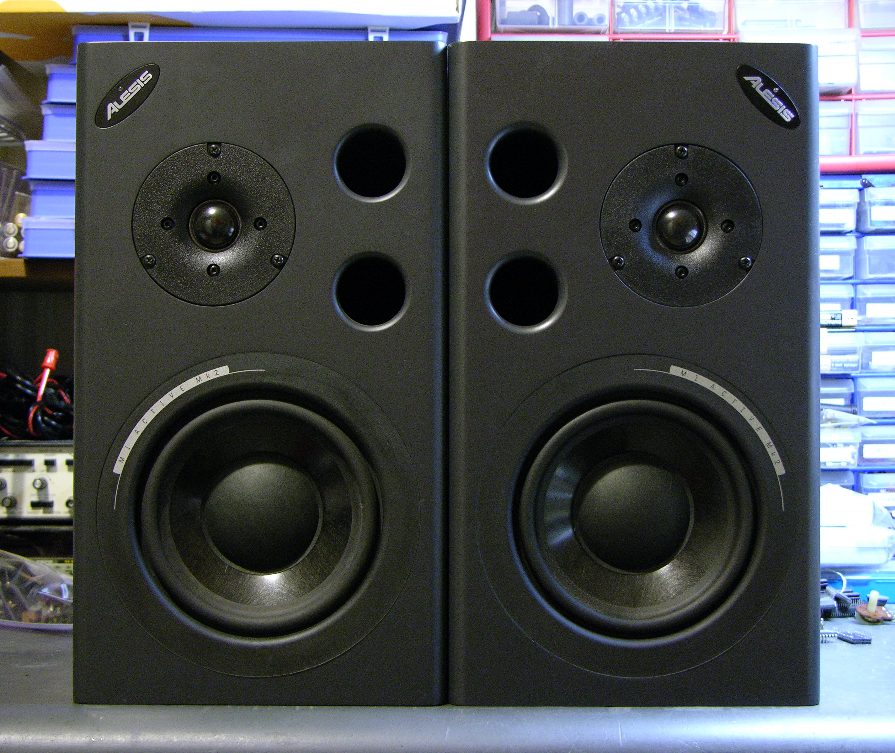
During installation, one of the speakers started winking its blue power light and ceased playing sound, and before the show another did as well. Steve found a Studio Central forum post suggesting that the problem was due to a failed electrolytic capacitor that gets baked by a hot resistor right next to it, and a quick peek inside confirmed that it was a likely explanation and fix.
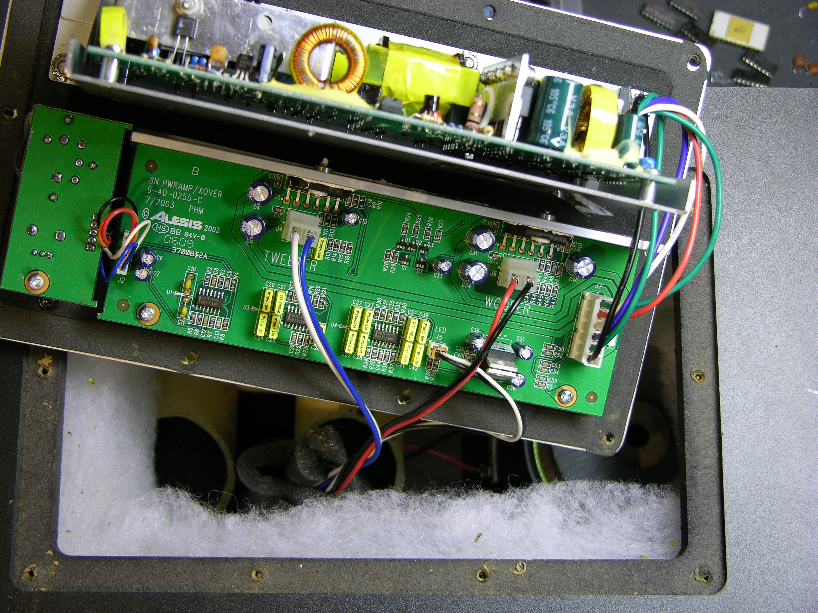
After unscrewing, the back panel lifts out and reveals the power supply board mounted vertically on a metal shield, and the crossover/amplifier board mounted flat on the panel.
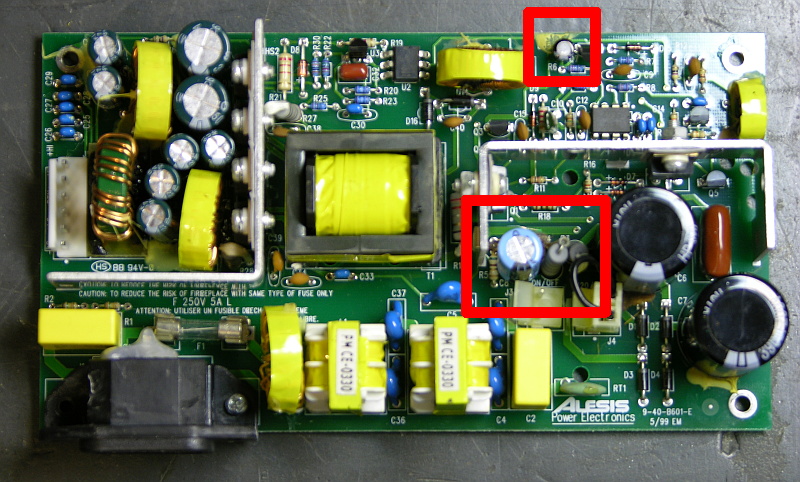
The naughty capacitor, C8 (actually its replacement after I finished), is in the center red rectangle next to the offending resistor. Another bad electrolytic capacitor whose number I forgot to catch is featured near the top of the board. Both of these tested bad with my Capacitor Wizard in-circuit equivalent series resistance (ESR) tester; all of the other electrolytics on the board tested good.
It was simple work to remove and replace the two capacitors on each board, and it brought both speakers back to life. Thank you, forum posts and Capacitor Wizard!
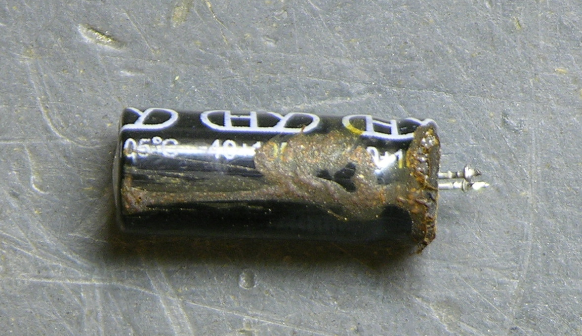
BTW, are electrolytics supposed to look like this?
Two caveats about this repair. First, I should have used 105°C capacitors, but I could only find 85°C caps on short notice, so these will fail quickly and need to be replaced again. At least now it’s known exactly what needs to be done. And second, the forum post suggests moving either the resistor or capacitor to get them further apart, which is a great idea but which I haven’t done yet. I’ve been trying to think up a clever way to stick a little heatsink on a vertically-mounted resistor, which might be a better solution yet.
Hi all
In my C8=330uF 35 V but I think it isn’t problem 330uF or 220uF.
You should first checked D1, D2, D3,D4 . If blow up Fuse 250V 5A, you should check: L1 and L2. I’m sure you have short circuit
If you supply 230V checked capacity C6 next Q2 , If 110V C6 next to C16.
I didn’ know nothing about firm Alesis but their SMPS with two filters on in and out voltage is design intentionally to damage in given time (5 years
), but this time is very short (this lived only 1.5 year at first user after bought) On board is date production: 19 03 2007 . I think they should give diagrams to help improve SMPS for users for free.
If they think about their customers seriously they should change SMPS for new better one for a small fee.
D9=BAV21
C8=220Uf, 35V
This is from the official parts list.
I also very much recommend checking everything in the AC circuit up to the bridge rectifier. I found a speaker with a bad solder joint near one of the AC line inductors. It caused many of the same symptoms as the leaky cap, but also added blowing fuses to the equation.
Cheers,
Pappy
Hi. one of my M1 Active 620s just died recently and I would like to fix it myself too. Would it be possible for one of you guys to email me the schematics and the parts list as well? Thanks a bunch!
owzhou@gmail.com
Hi,
I had the flashing light problem.
Replaces C8
Please advise the specs for C34, and C35. A friend currently has them to repair, and cannot see this detail.
Also RT1 blew while we were testing. Scorched the yellow cap next to it!!!
maske2g@hotmail.com
Hi
I have just bought my 2nd pair of these monitors for spares, as one of my first pair blew it’s psu.
I’ve tried to repair it twice now – I replaced Q1 and 2 (Q2 was short)
also RT1 had blown as with Chris M’s above. 2 of the rectifier diodes, the 2 caps C6 and C7 – one of these was bulging at the top. D14 up by the opto-coupler (short) C8 was leaking,
nothing else seemed to read wrong
but when I tested it Q2 blew again, the 2 rectifiers, and R15 kind of exploded – Very annoying. Any ideas?
cos I am near giving up -
I thought with a working board to compare and a circuit diagram, it should be dead easy but it’s just dead!
C34 = 0.047uF 10% 50V (ceramic)
C35 = 1.0uF 50V
RT1 = Thermistor, 10 Ohm 2A NTC
Cheers,
Pappy
Same issue for me, M1 mk2 actives that after pretty much exactly 5years packed in.. 1st one a month ago, blinking light first with very frequent intermittant sound then with a slow bass pop and squeal.. turned it off!
Next yesterday the other one started blinking and no sound.
Searched a few forums and C8 capacitor kept on coming up, opened them up – no visible signs on C8 to show it had packed in. only underneath the transformer PCB the offending hot resistor R4 and another one on other side had slight dark scorching on bottom of board.
So thought worth a try at DIY, went to Maplin – I think they were £0.20 each! They didn’t have exact same capacitor, so got 220uF 50V high heat 105, which helpful tech said shouldn’t affect it at all.
A bit nervous as hadn’t soldered in years and was quite tricky for a novice to cleanly remove the existing solder and cap. But with some reading up on how to’s to remove capacitors and resistors cleanly – tip is apply new solder on to the pin first then it will help melt the original solder, and very quickly whilst its still molten use a spring vacum solder remover and hey presto it sucks up all the new and old solder leaving a clean hole with pin.(my first few attempts without applying new solder started messing up the board and thought id wrecked it but it was ok)
Once id sussed this method, the second monitor was disassembled,new cap soundly in place and reassembled in 15 mins!
Next gingerly plugged one back in.. expecting a mighty pop but was fine and sounding like new, next other one plugged in and its perfect too.
So it really is the cure.. totally chuffed now as saved me ££s For anyone never soldered before its probably best to learn how to remove old solder on an old pcb with new and then resolder an old cap or resistor in again other wise you could mess up the board quite easily.
One thing that may have aided mine to fail may be that they haven’t really been turned off in 5yrs, my understanding was that with pro audio circuits it’s the on/off power surges that ruin them.. but in this case if they had been off 70% of the time would this have saved them? Does anyone have any knowledge or thoughts on this, though I think i’ll be turning them off when not using now to save the capacitors getting unessesary hot and drying out. But then I did read somewhere that they were manufactured with a 5yr lifespan.
mr teak
Mr. Teak, considering that almost everyone’s power supply fails by the capacitor drying out from being overheated by the resistor, I’d agree that with these speakers, it’s on-time, not on-cycles, that kills them.
well I fixed one of my 2 duds, thanks to pappy mcfae. It may have been a leg of L3 which was weak and when I picked up the board at some stage it snapped altogether. So had to solder a leg to it. I probably wouldn’t have looked very closely at these components if I hadn’t read the comments above – cheers.
I changed C8 and U1 (the 8 pin chip) checked everything a hundred times and plugged in closed my eyes and turned on – finally it worked.
So 1 board to go – this one I replaced a fair bit but didn’t replace the chip – so hopefully it had something to do with blowing R15 and Q1. Just need D16 and RT1 to complete….I hope. Could I use a 10 ohm resister instead of RT1 how would that effect it??
D16 I can only get a 3 Amp version not the 1 amp it’s supposed to be – is it like caps you can put in higher rated diodes? It’s an MUR 160 but I can only get MUR 360 from CPC ??
Anyway I’m getting there.
To paul p- As on caps, a higher voltage rating on power supply diodes should be no problem as long as the leads will fit into the circuit board holes.
yes I was thinking the leads looked larger on the picture – maybe i’ll go for the correct rating – they have them but only surface mount – so i might solder a couple of leads on it. Thanks for that
one of my mk2 m1s just died, thought it would be the c8 cap problem. on inspection the cap was fine, infact I think i have a newer pair (bought them secondhand) as c8 seams to be uprated to a 105 degree cap (no previous sign of repair) the problem was actually the first inductor L3, one of the legs had burnt out.
My 620 is DOA and I do see that the C8 is history, however I also see Q3 looking REAL rough (plastic missing and partial metal exposed). Can someone kindly provide the rating of this component. Also, maybe a direction on where to purchase the necessary components for this fix. This site has provided excellent information and I am thankful. A new board is out of my price range at the moment. Thank you in advance for your time and patience!
P.S. I can take a photo of the board and email it to anyone that would like to see if I am overlooking anything obvious.
Q3=2N4401
Cheers,
Pappy
Thank you for taking the time Pappy! I hope that is it. I will post my results once completed.
You’re welcome!
Cheers,
Pappy
Hey Pappy…
I was checking out my other (working 620) and found leakage from the C8 there as well. I have begun an order through Digi-Key and found one more issue. It appears that the C8 cap leakage has (possibly) damaged the diode (D5?) adjacent to it (on the DOA 620). Do you have a replacement number for this as well? Thank you soo kindly for your patience as this is getting more complex by the moment!
-Tal
Hi there,
Just wanted to say a massive THANKS to everyone here, I just fixed my dead Alesis M1Active 620 monitor (different than the one in picture above) by replacing c8 (original was 330 uF 35V) with a samwha 220uF 50V 105º. There werent any signs of burning on the actual c8, just a slight dark spot under the resistor neighbour of c8. I went ahead and replaced it, and left the legs a bit longer than the original to separate a bit from the heat that caused the failure. The first try it didn´t work, so I desoldered it again, cleaned up the spot a bit better, and made sure both legs were connecting to the right places. And it worked!
I have to say I wouldn´t have been as confident doing my first ever repair if I didn´t read your comments above, now I have my monitors working perfectly! (for 125 chilean pesos! …like 25 cents
Cheers!
D5=BAV21
I have a parts list, so you can rest assured I have all the part numbers.
Cheers,
Pappy
I have done this repair on both of my M1s. My caps didn’t look obviously damaged like yours but they were bad nonetheless. The value for the part doesn’t seem to be too critical, as I just used some electrolytics that I had on hand that were close values. One of them has been in continuous use for about a year now without any problems.
well I think i’ve given up on my last board. I put all the components in
rect diodes, RT1 the 2 large caps, C8, Q1, Q2, R15, repaired one of the small coil transformers, D14, D16, repaired D5 (leg corroded from capacitor leak) Q4, U1.
Plugged in and ..BANG…..again! it seemed to come from the area of Q2 but nothing seems to have blown – all components test ok – aaaarggggghhhh!
Maybe I will save this one for retirement!!
After replacing C8 and Q3 I buttoned my 620 back up and proceeded to power it up. I was greeted with a pop from RT1 and a blown fuse. Can anyone shed some light into this problem. There had been mention in another post that perhaps the U1 component (UC3844N) was defective, however I have yet to see much more on this. Any help would be extremely appreciated. I will now start working on the other 620 and have better to report. Thanks to all here!!
Replacing C8 did the trick on the other 620. A big thank you to all the posts and Pappy for the parts info.! Just one more monitor (see previous post) to go!
Hopefully there is someone out there that can shed some light on this one as I am nearing the “giving up” stage.
Tal,
I’d check all semiconductors, especially the ones that excite the “flyback” transformer. Since that would include that IC, I’d recommend replacing it just out of hand. When checking, don’t forget to check for emitter to collector shorts. Also, check all the inductors on the AC line. I had a bad one that caused a fuse pop.
Be careful when digging off the silicone they use to stick the inductors in place. Slipping tools can break things.
Cheers,
Pappy
Thanks Pappy! I will give it my best that is for sure. I had already ordered the IC so I will start there although I will now have to order the RT1 from digikey. Looks like I will have a short electronics “grocery list” when I am done but this will hopefully take care of it. I greatly appreciate your expertise and, mostly, your patience!
P.S. Do I need a scope to check for the emitter to collector shorts or will my multimeter be sufficient? It has been a long time (1980′s) since attending electronics trade school (elementary music teacher now).
Tal,
Use your DVM in diode check mode. Check emitter to base. It will conduct in one direction, will not conduct in the other. Check collector to base. Same scenario. Emitter to collector should be an open circuit no matter the direction of the leads. If these are the readings you get, assume the transistor to be good. This applies to all bipolar transistors (Q3 through Q7 part numbers: Q3, Q6=2N4401 Q4, Q5, Q7=2N4403).
Q1 and 2 are enhancement mode MOSFET transistors. The drain and source are protected by a zener diode internally. You will get current flow in one direction, but not in the other, like you would for any other diode. The gate lead must show as open with respect to all other leads. If the gate lead shows as shorted, whether to drain or source, it’s definitely bad. If drain and source are shorted (most likely scenario) replace both Q1 and Q2. Part number irf840.
Observe meticulous ESD reduction protocols when working with MOSFET transistors. They are very, very sensitive to static, especially the gate lead.
Cheers,
Pappy
Thanks again Pappy! I will be engrossed in this for the next couple of days and I will let you know the outcome.
Pappy,
Here is what I have found;
1) L4 has material coming out of the bottom of it (defective?)
2) Both IRF480 were shorted (gate lead shorted)
3) Q4 has a hairline crack running down the side
4) RT1 is burnt (you had already given the numbers in a previous post I believe)
5) D14 was burnt up due to Q3 popping.
6) D3 and D2 appear to be gone as well
I guess I have a small shopping order for DigiKey! I went on their sit to reference the IRF480′s and had a hard time figuring out which one (one of the top three on this page? http://search.digikey.com/scripts/DkSearch/dksus.dll?Selection
Do you have part numbers for the aforementioned components? If this does not get it I may just throw in the towel on this one! My wife is wondering if I was going to marry this one!!
You have helped out enormously and I “Thank You” for your patience.
P.S. Is L4 next to the fuse? I cannot read the numbers on the board and this component appears to have black material in the inside of it.
I’ve been a tech for many yrs and the damage you report sounds catastrophic. You seem to have a massive short somewhere on the board or on the sound board. I’m amazed the fuse didn’t blow before all this happened but sometimes the short is so severe that everything “fries” before the fuse can react. (you might check the fuse, BTW). With this extent of damage there are probably other components that have been greatly weakened also and might be ready to fail soon. In my humble opinion, I’d consider the “patient died on the operating table” and get a new board. See what Pappy says, but it doesn’t seem worth the time and expense to try to revive it. Sorry.
Pappy,
Here is what I have found;
1) L4 has material coming out of the bottom of it (defective?)
I am not sure on that. Check to make sure that you don’t have a short between the inductors. As I recall, that passes both AC lines through. Is this correct? If it only passes one of the AC lines, then it should be fine. IN case it isn’t…
L4=Inductor, resonant, 25uH 3A. Alesis PN:7-20-0042
It’s probably best to buy their part, as it would be a direct replacement if it proves to be bad.
2) Both IRF480 were shorted (gate lead shorted)
3) Q4 has a hairline crack running down the side
4) RT1 is burnt (you had already given the numbers in a previous post I believe)
5) D14 was burnt up due to Q3 popping.
6) D3 and D2 appear to be gone as well
That’s definitely bad. I would now recommend you replace every semiconductor on the “high voltage” side, and check all resistors that are ten Ohms or less. Also check the diodes on the low voltage side of the flyback. I imagine they didn’t get hurt, but if they did, you will blow everything again if they are indeed shorted.
D1-4=1N4007 *
D10-13 MUR860 (600V,8A TO-220)
D14,16 MUR160 (600V,1A)
D8 1N4747 (20V, 1 Watt zener) *
Q3,6 2N4401 NPN *
Q4,5,7 2N4403 PNP *
Q1,2 you already know that one.
U1 IC modulator UC3844N *
U2 Opto-Isolator TCDT1124 *
U3 TL431 Reg adjust shunt 2.5-36V 100mA TO-92 *
D5-7,9,15 BAV21
Also check R15 (0.22 Ohm, 1 Watt) and r18 (100 Ohm, 1/4 Watt)…just in case.
Everything with the * are parts you should just replace, as it’s cheaper to do it all than to piecemeal it, and blow extra money. Replacing all the semiconductors would mean you would be following the old premise of all new parts, no old comebacks, or fuses popping. If it were me, I’d replace everything and be done with it.
Cheers,
Pappy
Do not plug the PS into the amp board until you are sure it’s not shorted as well. If either of those amps are fried, they will also have to be replaced.
Yes, that is fairly catastrophic damage, but I’ve replaced entire stereo channels in the old days of discrete bipolar direct connect audio power amplifiers. If you replace things, and get another poof with it not connected to the amp board, then yes, it is time to lay that one to rest and call in a new recruit.
Cheers,
Pappy
Thanks Allen and Pappy for your guidance on this one. I will have to weigh my options here as a new power supply board runs about $100.00
http://www.instrumentalparts.com/alm1acmkm1mk.html
One out of two 620′s is not bad and I am very grateful for the expertise and patience on this forum. I will post a follow up once I get my bearings straight. Take care!
P.S. A power conditioner and a surge protection device are now in place in my studio for safe measure.
-Tal
Good luck with the unit, if you decide to fix it. If not, and there’s no core on the old one, I’d take it. I can test my skills, and have a spare for when the other speaker we’re using gets sick.
I love a challenge.
Cheers,
Pappy
Pappy,
You will get first dibs my friend! I will be in touch and thanks again!!
-Tal
Awesome!
Cheers,
Pappy
Please, could someone tell the specifications for capacitor C16 (in 240 V version)?
C16=0.68uF film 100v.
Cheers,
Pappy
Thx, Pappy!
Pappy,
I am placing an order with Digi-Key and I found everything except the following:
U2 Opto-Isolator TCDT1124 *
D5-7,9,15 BAV21 (order 20,00 or more?)
RT1 = Thermistor, 10 Ohm 2A NTC
Do you have any other sources that I might tap in to? I will wait to hear from you before I order these components from Digi-Key. As always thank you for your expertise and patience.
-Tal
For wholesale parts, I tend to use Mouser. I would be very surprised if they didn’t have what’s left that you need. There might also be a specialty electronic shop in or near your town. If you can’t find any other source, I do have the Alesis part numbers if you wish to order from them. And somehow, I don’t think you need 20,000 BAV21′s. hehehehe
Always remember, Google is your friend.
Cheers,
Pappy
I have two of these units that have bulging caps at C8 but also darkened burn spots under the board at R27. Can anyone provide the specifics on the R27 location?
I’m not sure what you mean by, “the specifics on the R27 location…” except to tell you that the resistor is probably mounted just above the R27 markings on the board.
R27 is a 100 Ohm 1 watt resistor, as is r28. As long as they read properly for resistance, they should be okay. If the solder on their pads is looking a little grey and flaky, you might want to lay down some fresh solder on the pads. Flux will probably help make it work better, too.
Cheers,
Pappy
Thanks Pappy. I was needing the Ohms and wattage for the resistor. You got me on the right track now. Thanks for your help!
Glad to be of help.
Cheers,
Pappy
hello ,i just notice i have little hum in my speaker,and i am sure it is not power board causing this problem,it is the other board,does anyone have any idea what to check on amplifiers board?speaker is working good,just that hum,thanks
to Marek: Need more info. Does the speaker hum when the input cable is not plugged in? If unplugging the speaker stops the hum you may have a bad cable or a problem in the device driving the speaker.
to alan ,it is there all the time,even if is cable unplugged,half year ago i had problem with this speaker,power supply was gone,i fixed it,but there is that hum there since that time,it is not loud,but my friend has same problem with hum,so we trying to fix it,maybe somebody here had same problem
to Marek – OK. is it very low pitched (as like about as low as you can hum yourself) or slightly higher? Or does it have a “high-buzzy” sound? Sometimes hum problems can be pretty tricky to figure out but let’s continue on. I’m hoping Pappy will get involved eventually since he is the Wizard.
I’m not a wizard, but I’ve been mulling over the possible causes.
Does the position of the volume control on the rear change the tone or loudness of the hum? If no, then it’s a loose connector inside. If yes, then there might be something in the room… such as fluorescent lamps that have a tendency to radiate RF as they operate. Some devices are sensitive to this. Also, check the solder joints where the sound cable moves from the volume control to the amp board, and on the back of the volume control board as well.
As a general rule, most amplifiers will emit some noise at quiescence. The amp boards in these speakers are designed to minimize this, as they are shielded to ground everywhere but where the other traces move other signals and voltages around.
The power supply is engineered to stop 60Hz entirely, as the incoming 60Hz AC is rectified, filtered by a relatively low capacitance electrolytic to excite the flyback transformer with very high frequencies that allow for smaller caps on the output of the power supply circuit.
If you were to hear any noise from the speakers that is power supply related, you would be much more likely to hear high frequency noise as opposed to 60Hz. If you hear 60Hz, that points to cabling or solder joint issues, or a serious source of noise, such as the aforementioned fluorescent lights, or in-switch incandescent dimmers.
Good luck on the hunt.
Cheers,
Pappy
thanks to you guys,to Pappy mcfae,i don’t think so it is something like that,because other speaker is perfect,and this one was burnt,half year ago i fixed it,but that hum is there since that fixing,but it is not big deal for me i can live with that hum,when i am listening music it is not noticeable ,but my friend has same problem and he is music producer and it annoys him,so we trying to sort it out,i think it must be something with amplifier board,it is high pitched hum in tweeter,thanks