July 7, 2008
Welcome, MAKE: Blog readers!
Whoever posted this to the MAKE: Blog jumped the gun a bit — I haven’t interfaced anything to a synthesizer yet. What I found in the Baldwin pedal isn’t suitable for interfacing and is (in my opinion) worthy of preservation, so this post is just a teardown of the Baldwin pedal showing the intriguing mechanism inside.
I have since gathered all the parts I’m going to use to build the MIDI volume/expression pedal and expect to do that within a few days; so if you’re interested, please check back!
I want to build a volume pedal for my synthesizer(s), and I figured it’d be easier to do if I started with . . a volume pedal. So last night I went to storage and pulled the swell pedal out of Jacob’s most recently discarded electric organ, a Baldwin Model 5.
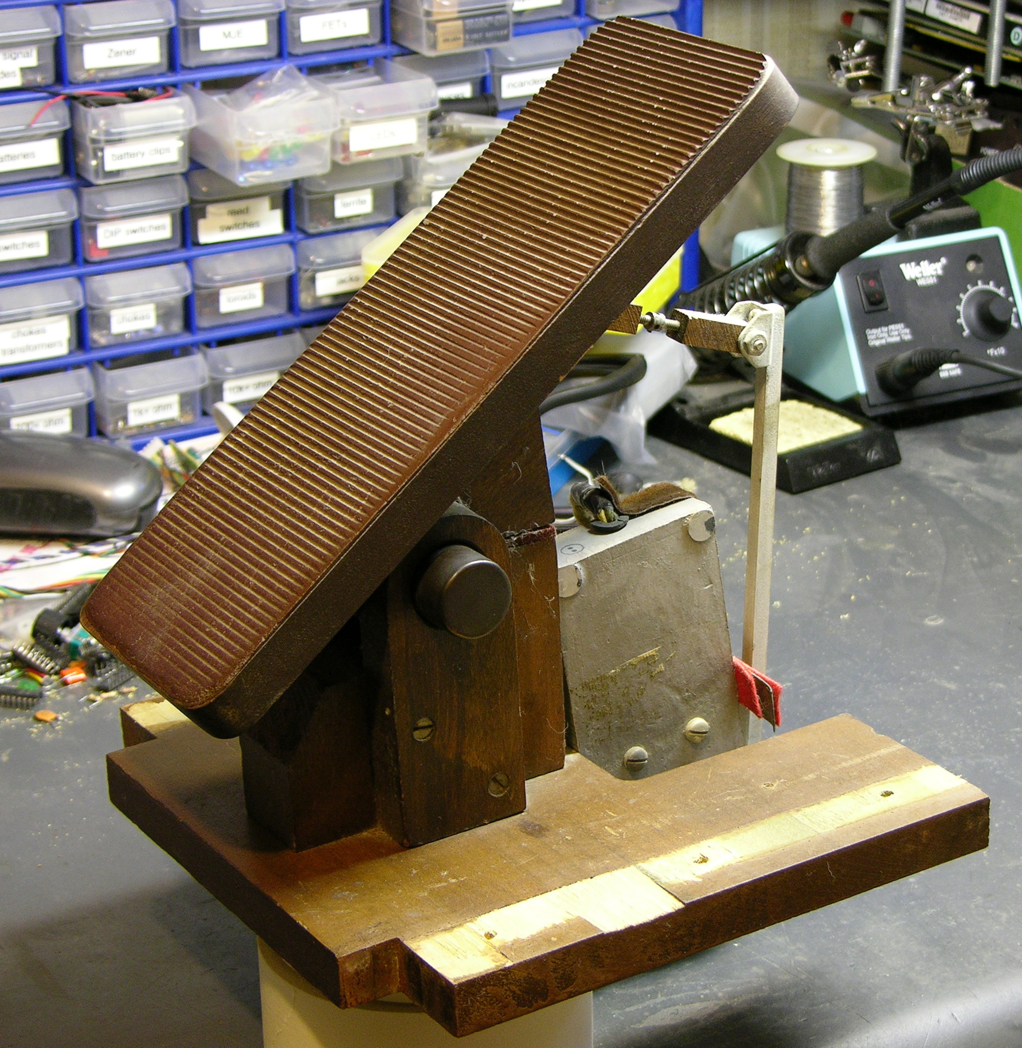
It’s actually quite a bit higher off the floor and more steeply angled than would really suit me; but I had it on hand and figured I might as well start working with it. As it turns out, I’m not going to retrofit this, and I’ll show you why in a little bit.
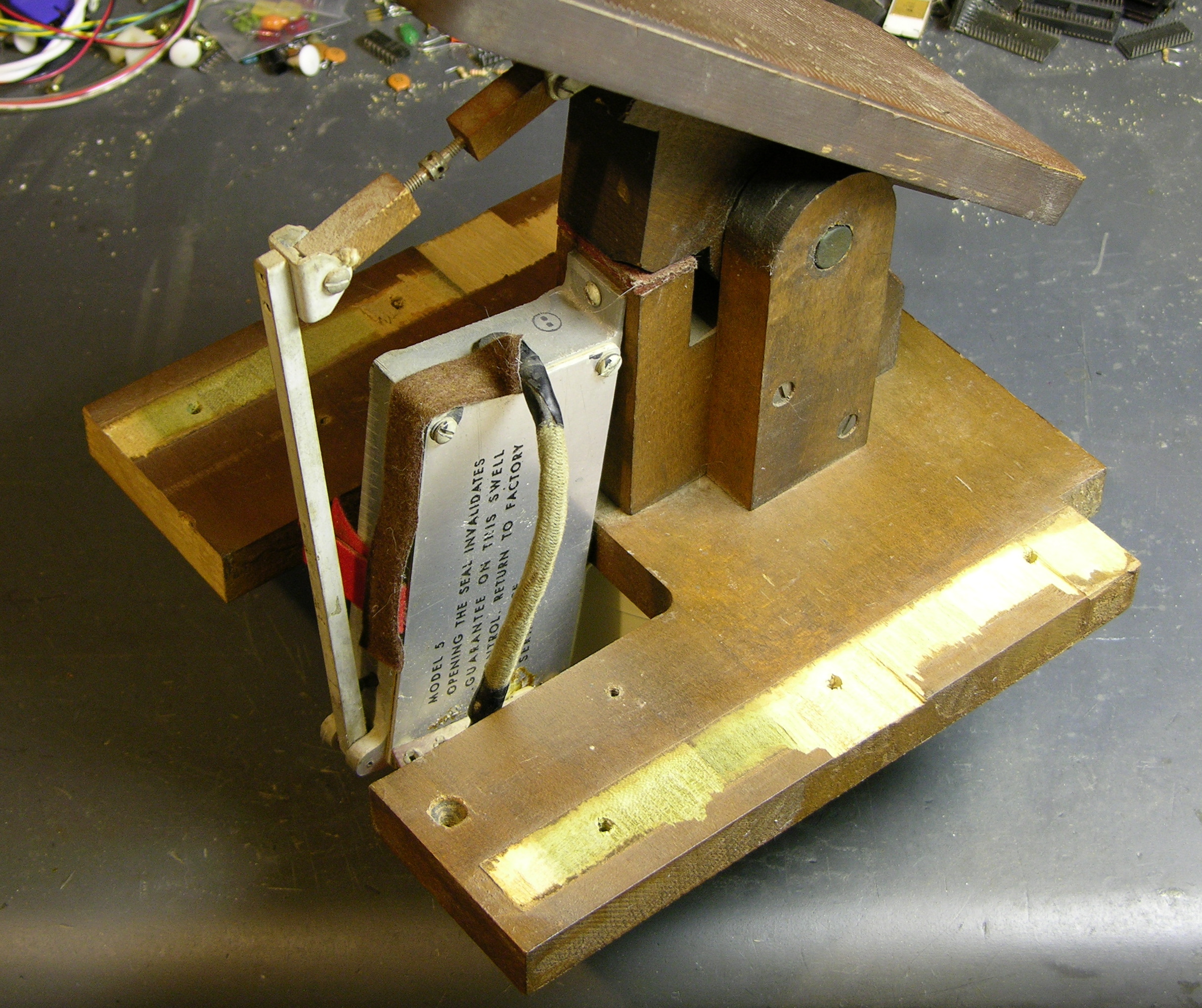
Rocking the pedal forward pushes the square lever away from the box, and rocking it back pushes the lever toward the box and presses a pin at the base of the lever into the box.
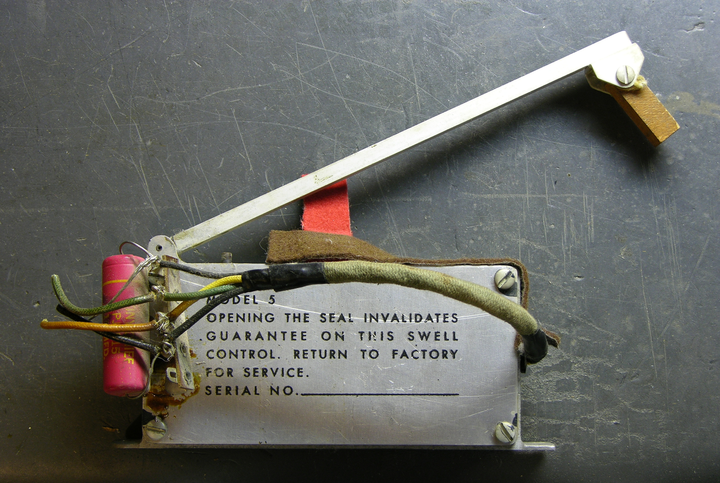
The lever and box assembly looks kind of like a giant microswitch. Or a bird with a long neck.
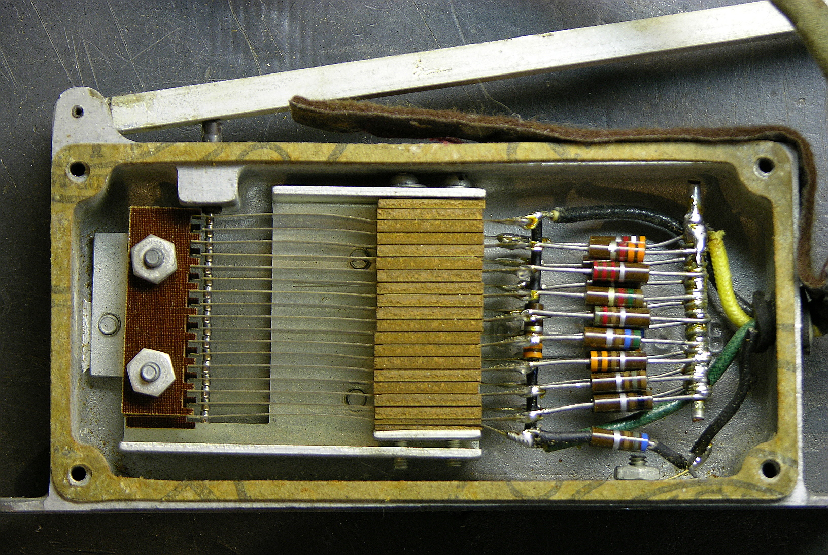
Here’s the part that makes me say, “Wow.” Apparently potentiometers hadn’t been invented yet (I think I’m joking), or weren’t available with a high enough power rating to use in this volume control circuit.
The volume pedal’s lever presses against a ladder of leaf switches (it’s hard to see, but all the contacts at the left end of the leaves are normally open, but only barely) wired to a resistor ladder. Pressing the pedal connects together increasing numbers of leaves and shorts across increasing numbers of resistors. Wow, wow, wow.
I just don’t feel right about dismantling this to stick in a potentiometer (nor are the mechanics of it really built to make that easy).
So now I’m looking for another swell pedal (with a pot) to repurpose, ideally a twin swell pedal like what’s on Jacob’s current organ. I don’t find much on eBay, and I’m not sure where else to look.
Possibly more mechanically reliable than the linear pots available at that time?
Mike, could be.
I wish I could find information about the age of the organ. I didn’t see a date on the information plate, and I’m not finding much online — just one reference to a church installing one in 1955.
Not knowing when this was made I would say that potentiometers did exist, but were not of very good quality. I know that for higher current applications they used nichrome wire wrapped around a dielectric card. As a matter of fact I had a rotary nichrome potentiometer that had failed because it had too much current, and it was only used as a volume control for a speaker. I’m sure it was probably from the 70′s because that is when the speaker system was installed. Actually the system hadn’t been updated until very recently. Anyway they probably chose to go this route because it was the most reliable system they could come up with, and who wants to hear clicks an clacks coming from a potentiometer that almost works right.
Now, wouldn’t that make it a *digital* swell peddle?:P
wackyvorlon, the swell pedal certainly has discrete rather than continuous volume, but it’s too late at night for me to think very hard about whether that truly makes it digital.
For what it’s worth, my intent is to build a digital pedal (or pedal set), by using the Arduino to do A/D conversion and generate (assignable) MIDI volume and/or expression signals, to feed into a synth that doesn’t have a jack for a volume pedal.
Note that potentiometers certainly did exist in the era when the organ was made. For evidence of that, I’ll note that some of the vacuum tube based radios of the 1920s used potentiometers for adjusting the filament current (e.g., My favourite is a Crosley model 51 that I own, made in about 1927.).
However, as one commenter points out, high power potentiometers were usually made by winding nichrome wire around a ceramic (or other high temperature insulating material) as a former, and using a sliding contact. That works, at least for power control, but as the windings age, the resistance may become nonlinear, and you may experience problems with intermittent contacts, which would introduce dropouts and noise into an audio signal (Not good for an organ!).
Carbon composition potentiometers have been available since at least
the early 1940s (and, probably the 1930s or even 1920s). But, they, too, experience a wear and noise problem.
The advantage of the switch approach is that it should be reasonably immune to noise, especially if the switch contacts are appropriately composed/plated. Additionally, with the correct selection of resistors, you can obtain any type of slope you desire (which is especially important for volume controls, since volume is inherently non-linear, e.g., audio taper). That’s not easy to do with a wire wound potentiometer, and, while it can be done with a carbon composition potentiometer, those still have problems.
For a modern approach, rather than going with a potentiometer (noise, wear, taper, etc.), I think I’d look at using some type of optical encoder driving some logic that controls a resistive ladder (e.g., Optical encoder controlled by a microcontroller which drives an array of (matched) MOSFET switches driving a resistive ladder. Or, something like that.).
Dave
Dave, I’m interested to hear that you’d be looking toward optical for modern applications, since (1) I’m about to build a MIDI interface for an existing potentiometer pedal (not this one), and (2) there are gazillions of potentiometers performing on stage every night of the week.
I never got to listen to this organ much before it was retired, but if it really only had sixteen discrete volumes, I’d be a little surprised if I couldn’t have heard the levels change as it was used. I know you can get high-resolution optical encoders that would offer many more than sixteen levels, and I’d wonder about using one to drive a digital pot, rather than a DIY ladder, which would seem awkward to build with as many steps as I think I’d want.
I’d also wonder about using an optointerruptor (or optoreflector) in analog mode, moving a slightly noncircular cam through it. You could shape the cam for whatever response curve you wanted; but I don’t know whether the optical sensors would be predictable enough to use that way?
All that still feels like overkill to me, though. My experience with stereos and guitars and synthesizers and amps suggests that pots are good enough — good enough to be in the preamplification stage of a transistor/IC circuit, anyway — especially if used regularly so they don’t get “crusty.” Do you disagree, or are you focusing more on higher-power applications?
Jose María Alcérreca has translated some of this page to Spanish and added a much more thorough explanation of the resistor ladder here:
http://pepevi.blogspot.com/2008/07/abrir-el-precinto-invalida-la-garanta.html
For convenience, here’s the Google translation to English.
Thanks, Jose!
Thank you for letting me use the pics!
Haha the translation is hilarious. “What is asking screams” -> “It’s begging for it!”
By the way, not suitable for interfacing? just plug in 5V and read the 0~5 output, right? I’m sure three of the four wires act as a variable resistor.
pepevi, you’re probably right — and it occurs to me that the external capacitor could be used to smooth the output voltage so transitions between the sixteen positions aren’t as noticeable.
What I should say, then, is that this pedal is large and unwieldy, has to be mounted on a stand because of the way the electronics enclosure hangs down, and is at a steeper angle than I like for a standalone pedal; and that I’ve already borrowed a sleek standalone pedal; so I’m not highly motivated to pursue confirming that this one would work. Fair enough?
Well, I have a couple of reasons for going with the optical encoder. Firstly, it reproduces the original design (and, there’s a lot to be said for authenticity, even if it’s done using modern components). Secondly, since the control will be in almost continuous motion, I’m a little afraid of the wear on a potentiometer, especially over a period of years, which a quality organ may last for. Designing a volume control with a potentiometer is a bit different than designing the swell pedal of an organ, since the volume control of an amplifier is usually set once per session and left alone, but the swell pedal of an organ is in almost constant motion.
Another issue is that you didn’t show the exact circuit being used with the switched resistor ladder. If it’s switching the audio directly, then there may be a noticeable shift in the volume. However, I seem to remember that this was being used with a vacuum tube based organ, so I’m wondering if the switched resistive ladder may have been controlling the gain of a variable mu vacuum tube. This would allow a time constant to be implemented such that the volume change may be rather slow (e.g., more of a swell than a switch).
As for building a discrete resistive ladder, that shouldn’t be too much trouble with only 16 levels. It may not even be a major problem, at least for onesie-twosies, with more levels, where you could hand pick the resistance values for the resistors being used. But, I certainly wouldn’t want to put a design like that into production with discrete components. Of course, you could use a packaged resistive network, where the resistors are matched.
As for using an analog optical sensor, that might actually work reasonably well, if you picked the correct type of optical sensor, although designing the optical path might be a bit of a trick (especially making it stable enough so that mechanical motion didn’t affect the volume). Phototransistors tend to be rather non-linear, but something like a Cadmium Sulfide photocell might work well.
Dave
Okay, Dave, I hadn’t picked up that you were speaking particularly of redesigning a swell pedal. In that and related contexts, everything you say makes sense, and I don’t have to wonder why you eschew potentiometers for general-purpose volume control.
This post pushed me to open my uncle’s Lowrey organ. Again in spanish but the pictures could be interesting. [Google translation]
Nice Post, keep up the good work looks great..