Over the holidays, I tried to fix my Roomba Scheduler. I ended up deciding not to try to trace from the battery connector to locate what part had shorted/burned when I connected a rebuilt battery with reverse polarity, I found an eBay seller with remanufactured main boards, and I ordered one for $20.
Yesterday I had time to swap it out and get Roomba working again.
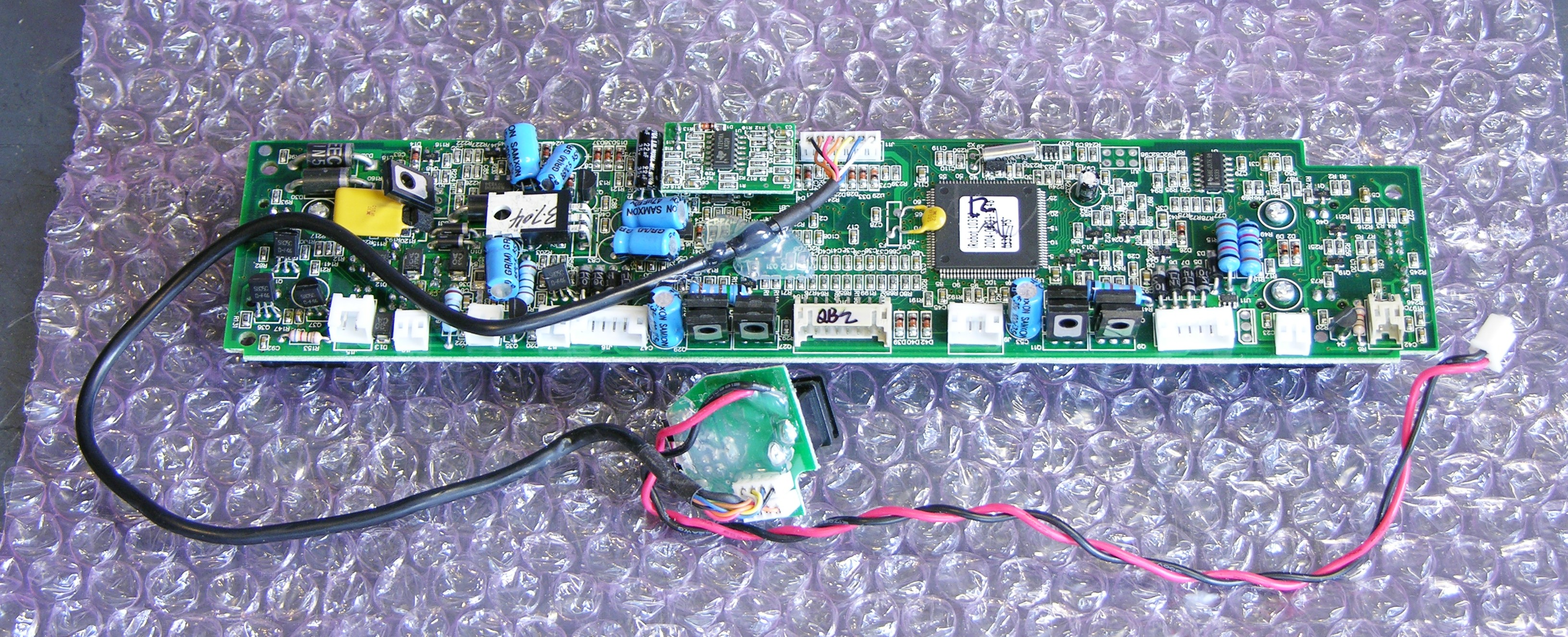
Board Replacement
I had the new board completely mounted and half the connectors wired up when I noticed the first problem:
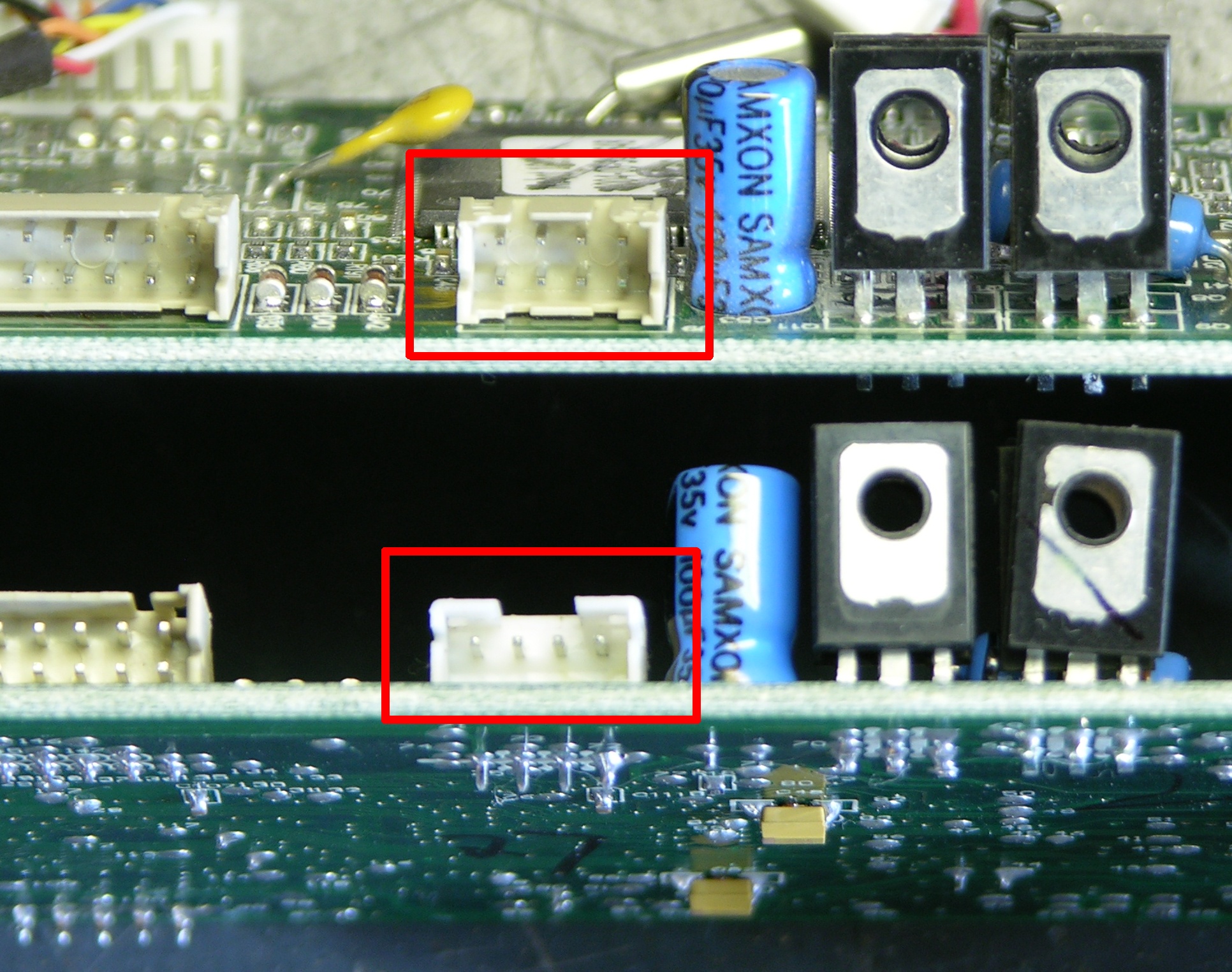
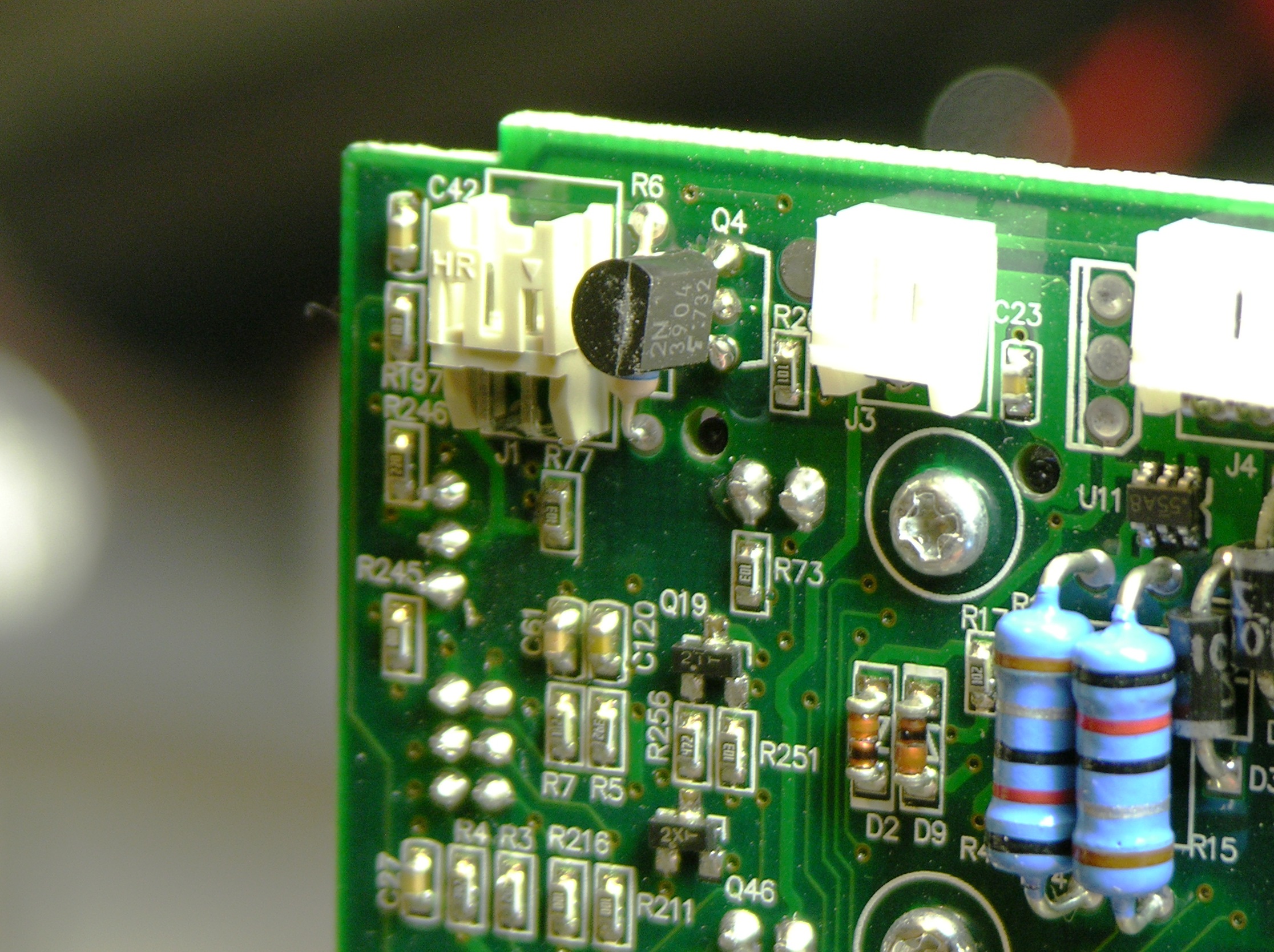
My Roomba has two dirt detectors, and J9 has two rows of pins, one row to each piezo assembly. The refurbed MB had a single-row J9, apparently from an earlier model with a single dirt detector.
I debated a bit about contacting the seller, but decided it was a waste of his time and mine to ask for a replacement board when I had everything I needed already at hand. I desoldered J9 from my original board (tedious heat-tug-heat-tug-heat-tug that demonstrates how good J9′s plastic is because it didn’t melt and how good the PCB is because the only thing I ruined was one of the test points), and had a much easier time desoldering the single-row J9 from the new board.
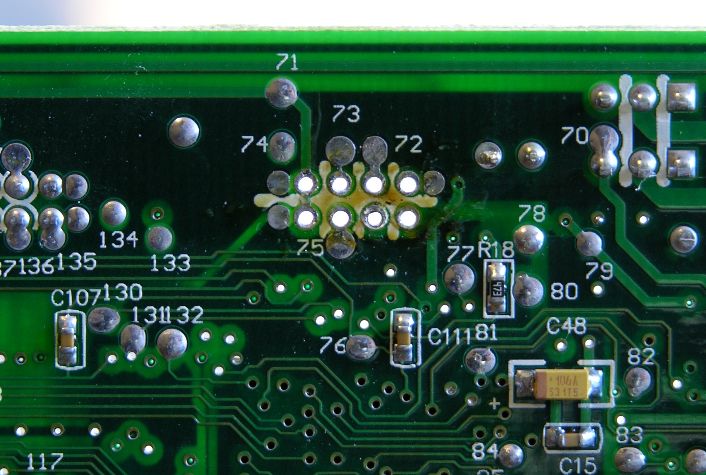
Then I got frustrated trying to get the solder out of the through holes. I had some success adding solder to the holes and applying solder wick, but there were three holes I just couldn’t get. Finally I gave up and pulled out the PCB drill bit set — a #68 bit spun gently by hand turns out to be just the ticket for cleaning the solder out of these holes. (Never again will I try to wick solder out of empty holes.)

I cleaned the two-row jack’s leads with a wire brush, soldered it in, took a picture from an angle that looks like I still have the single-row jack in the board, and reassembled Roomba.
Attempt #1
I was delighted to see it turn on when I pressed the power button. I knew that should be what would happen, but it was still gratifying to see it actually happen.
Prematurely. Gratifying.
I took it to the living room to vacuum, hit Clean, and it just burped. It burped when I hit any button. Grrrr.
Diagnostics and Cliff Sensors
The first page I found when searching for why it was “burping” was What is Roomba saying to me?, which says that the “eh” sound means there’s a faulty cliff sensor.
I relocated the Roomba Discovery models’ diagnostic tests page and ran through the individual sensor diagnostics. On test 2, outer cliff sensors, only the starboard-most sensor worked properly; the outer port sensor showed “cliff” all the time. On test 3, both inner sensors showed “cliff” all the time.
Gathering more test materials and retesting, I found that only the outer starboard sensor’s IR LED was lighting my infrared sensor card (apparently no longer sold at Radio Shack, but apparently formerly part number 276-099 and/or 276-1099), and the cliff-sensor IR LEDs were dark. Further, shining the virtual wall’s IR LED beacon into the cliff sensors caused the diagnostic LEDs to flicker, indicating that the cliff-sensor IR detectors (phototransistors or photodiodes) were working properly, so the problem definitely seemed to be in the LEDs.
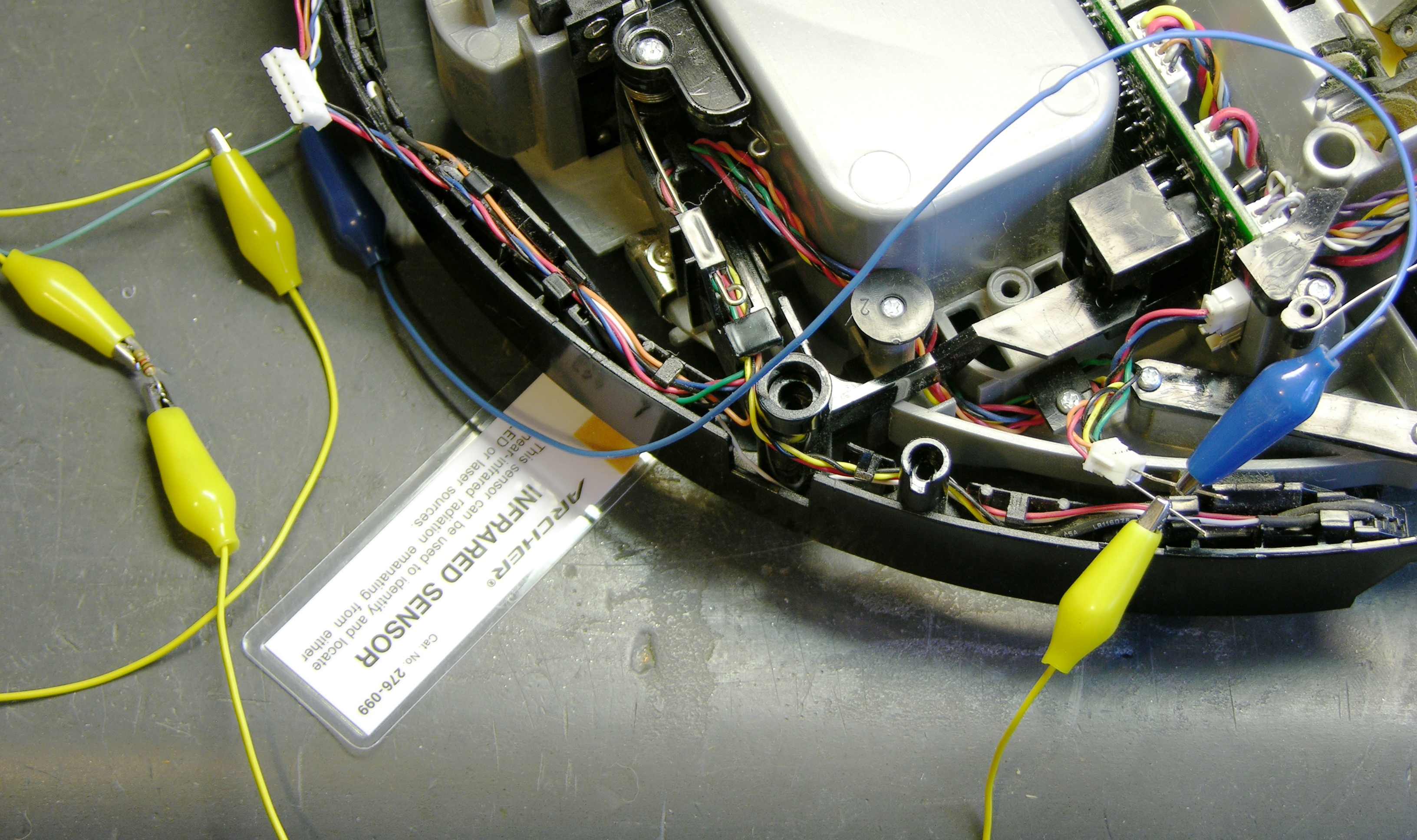
All three of the dark LEDs individually checked good with the diode tester on my multimeter. Tracing the cliff sensors’ LEDs, I found that the three dark ones were all powered in a single series circuit, fed by the red (anode) and orange (cathode) wires in the top row of J24 at the port end of the main board.
My meter’s diode tester didn’t use a high enough voltage to overcome the forward voltage drop of the series string, so I hooked my bench power supply to a 1KΩ resistor and the series chain. All the LEDs now glowed on my IR sensor card, so the LEDs weren’t faulty (which I had assumed anyway) — the problem was with the driver.
Robot Reviews Forum and Q4 LED Driver
Searching online for advice, I quickly found this forum post titled “Cliff sensor failure apart from one” complaining of exactly the same problem. “Gordon,” a very knowledgeable contributor, indicated that the dark LEDs were all driven by the same transistor, Q4.
I found Q4 on the board and it was twisted, so I straightened it without particularly thinking. (This fact isn’t relevant yet. Just wait.)
Gordon indicated which MB test points correspond to which Q4 pins, provided an apparently reverse-engineered and incredibly helpful schematic of the cliff-sensor LED drive system, and indicated that the Q4 and Q37 bases should have a 1kHz square wave on them, with a corresponding signal on the collectors.
I put the scope on Q4 and its base was oscillating nicely, but its collector stayed high. This made me suspect a faulty Q4, so I quickly and cleanly desoldered it and checked it in my out-of-circuit transistor tester. The tester said it was good with a β of about 220, which wasn’t what I wanted to see. I wanted it to be broken.
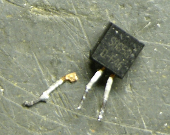
And then while I was straightening the leads and pondering what to do next, the emitter leg felt loose and I pulled it out with my fingers. Removed, it looked rather like a dessicated cricket leg you’d find in a corner.
I don’t have SS8050s on hand (that I know of), but they’re all over the MB and appear to be used as general-purpose transistors. I found a 2N3904 with the same pinout in my parts bin (if you think all TO-92 transistors with the same part number have the same pinout, you haven’t shopped enough different manufacturers), tested about the same β, installed it, and the IR LEDs all glowed.
I could have pulled an SS8050 from my original MB, but (1) I wanted to keep it intact, and (2) I wanted to demonstrate that another transistor would work. And so it did!
Sweet, Sweet Success
Roomba powered up again, but this time it didn’t burp (I mean “eh”) when I hit buttons, and it went straight into cleaning mode. Woo-hoo! I took it to the living room and let it clean, and it ran the course and picked up all the cat hair.
Today I emailed the eBay seller just to let him know what had happened. I wasn’t upset and I left him all positive feedback because the board he sold me fixed my problems within my abilities, plus I may have broken Q4 myself while straightening it, plus I had some fun tracing the problem. But I thought he should know what happened so he could check future boards more carefully for customers less fascinated by the process of repair.
He replied:
wow, yes you went above and beyond what I would expect. Thanks for helping out, i’m sorry you had to do so much.
sounds like the glass is half full with you.
There may be some truth to that.
I’m surprised you don’t have a springloaded solder-sucker in your toolbox. I’ve got one around I’ve used for years, and it’s just the thing for removing solder from those through-plated holes. This one looks pretty similar to the one I’ve got:
http://www.apogeekits.com/desoldering_tool_anti-static.htm
You just push in the plunger til it locks, heat with the iron in one hand, switch from iron to sucker and push the button in one quick motion, and it vacuums up all the molten solder in the vicinity of the tip.
Aaron, good point and worth mentioning. I do have a spring-plunger solder sucker, and a squeeze-bulb solder sucker, and I think at least one other kind. But somehow when I press the trigger and action and reaction happen, I have a nasty tendency to gouge circuit boards and ruin solder pads. I may just be clumsy, but I’ve learned my own limitations.
I’d love to have a full-fledged vacuum pump rework station, but can’t quite justify it for the small amount of true rework I do.
A fine repair job and diagnosing. I will have to try the PCB drill trick for cleaning out those pesky holes. My solder sucker never seems to work right for me. Thanks for sharing.
One trick for cleaning out solder holes is to use an Aluminum or stainless steel probe. The idea is to heat the solder to well above the melting point, and then push the probe through the hole. Since both Aluminum and stainless steel aren’t solderable (well, without some specialized tricks), the solder won’t stick to the probe, but will be pushed out of the hole. Of course, that can get tedious if you’re having to do a lot of holes.
Another trick is to use an air compressor to spray a jet of air through the holes. The problem with this is that it tends to blow blobs of molten solder all over the place (Use appropriate eye/skin protection! And, do it in a workshop where you don’t care if you have solder splatters on the floor, wall, ceiling, etc.). Most people have some form of air compressor, while few have a vacuum pump (although the vacuum pump tends to be quite a bit cleaner).
Dave
Keith, after you soldered the old 8-pin dirt detector connector onto the new PCB, did both detectors work? Or was that just a physical fix, so you could physically plug them both in to the new PCB? I’m wondering if the single-detector PCB is different and cannot support two detectors, even with the 8-pin connector soldered in. Thanks – Jim
Jim, I don’t actually know whether both detectors were (are) working, and it seems like it could be fairly hard to stage a test that would determine it. But the PCB photograph sure looks like both header rows are wired together in parallel, which would suggest that both detectors will work. If you have yours out, you could verify with a continuity tester.
Hey next time just remove the plastic plug insert guide from the MB side it comes right off and plug in one side or the other it will work to. Just in case anyone else has this problem I had the same problem.
Hi,
I am having a problem charging my scheduler, Would you know where can I get the charging schematic from.
Regards
Issam
Issam, I doubt you can get Roomba schematics unless you operate an iRobot service center.