A Theremin is an electronic instrument played by waving your hands in the air near a couple of antennae. It has matched pairs of high-frequency oscillators, and the change in capacitance due to the proximity of your hand changes the frequency one oscillator in the pair, causing “beats” (heterodyning) between the pair that form audible wavelengths. The Theremin was invented early in the 20th century by Leon Theremin, a Russian physicist. It’s the spooky sound you hear in the Beach Boy’s “Good Vibrations”–although that was actually recorded with an electro-theremin, a different instrument designed to mimic the Theremin’s sound.
I don’t know when I first became aware of Theremins, but I know I’ve wanted one at least since February of 1996, when Electronics Now published “Build this Theremin,” by John Simonton of PAiA Corporation. The full PCB layout and parts were published in the magazine, and PAiA has also sold their “Theremax” kit continuously since then.
And I finally ordered one.
Two, actually; my friend Cort wants one as well.
They arrived about a week later.
Board Assembly
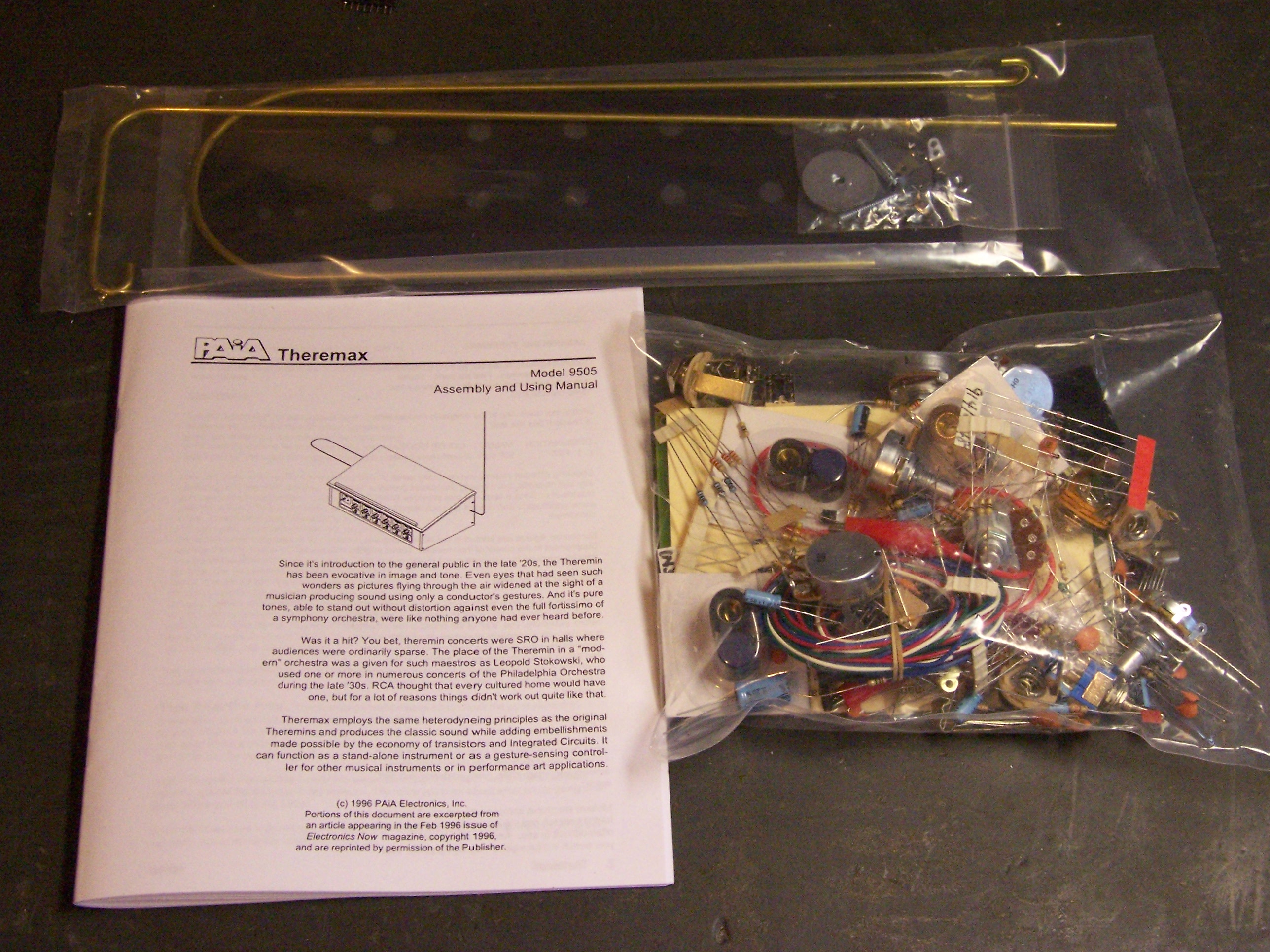
I bought the kit with the PCB and all components, and the separate partial case kit with the antennae and a nicely screened front panel. The full case kit was another $60, and I figured I could make a case that I’d be happy with for less than that. I think it says a lot about PAiA and their understanding of the hobbyist marketplace that they offer so many options, instead of forcing everyone into the same cookie cutter package.
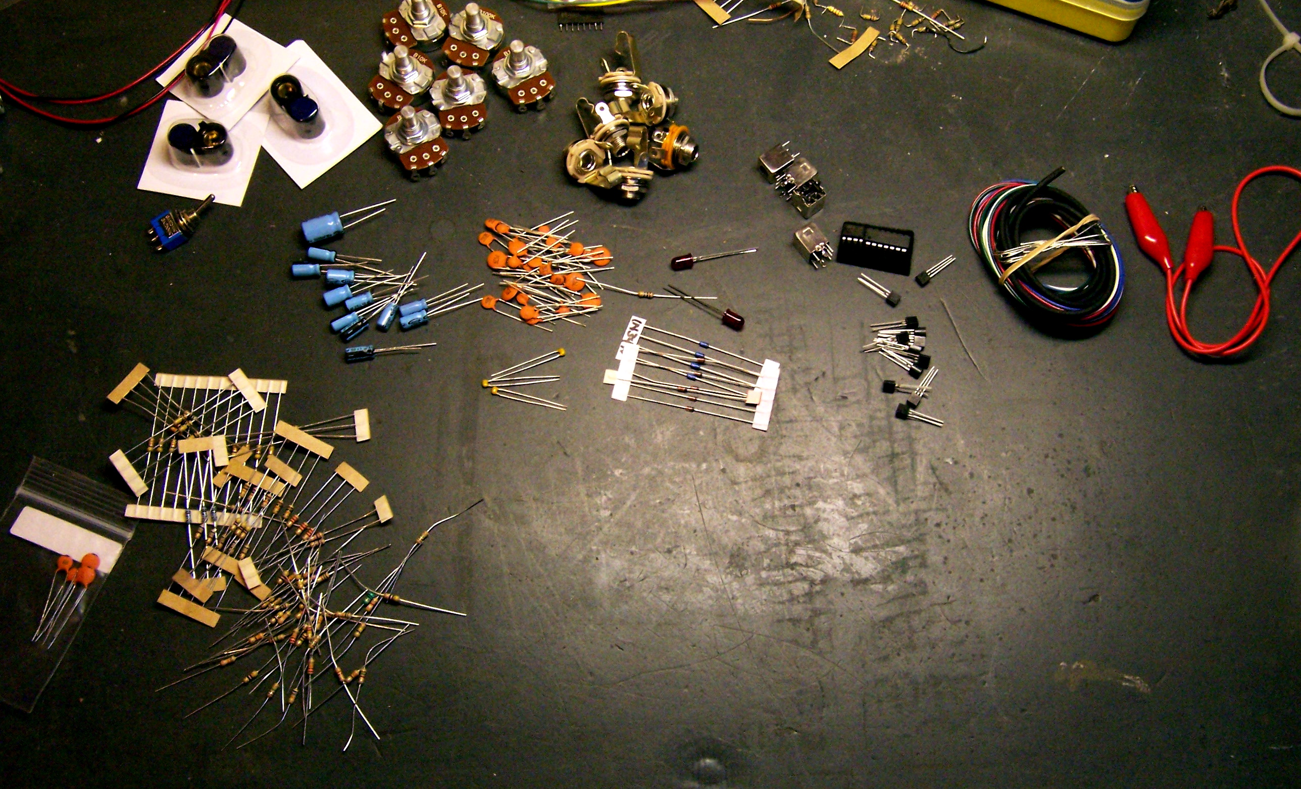
The first thing I did was sort out all of the components. There are dozens of resistors and capacitors, a handful of transistors, four tunable inductors for the oscillators, pots and jacks for the panel (included in the parts kit, even if you don’t buy the panel), and miscellaneous bits like LEDs and ICs. They even threw in hookup wire to connect the PCB to the control panel, and a gator jumper for bypassing the volume control during one stage of hookup–literally every part you need to get up and going, except solder.
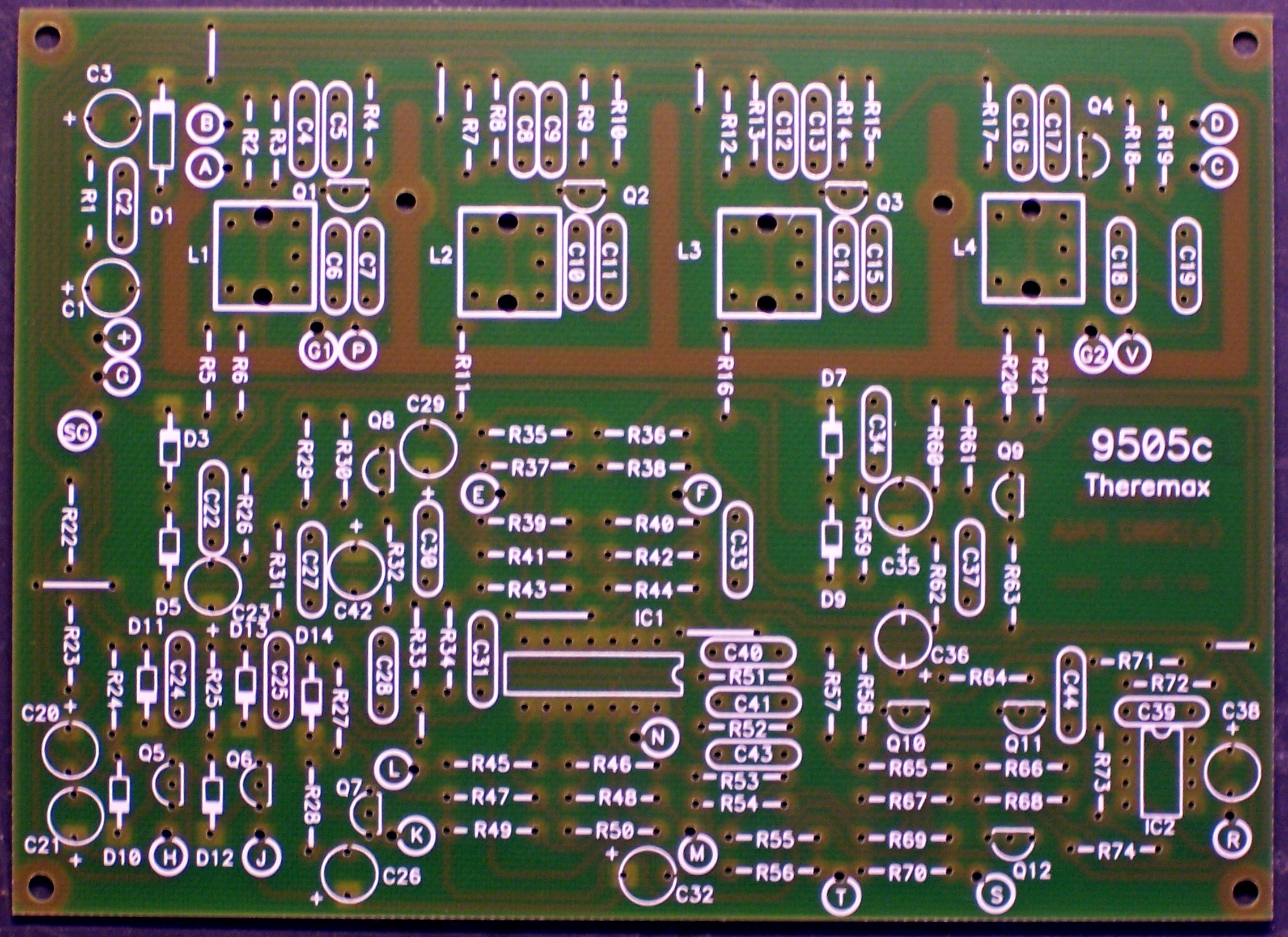
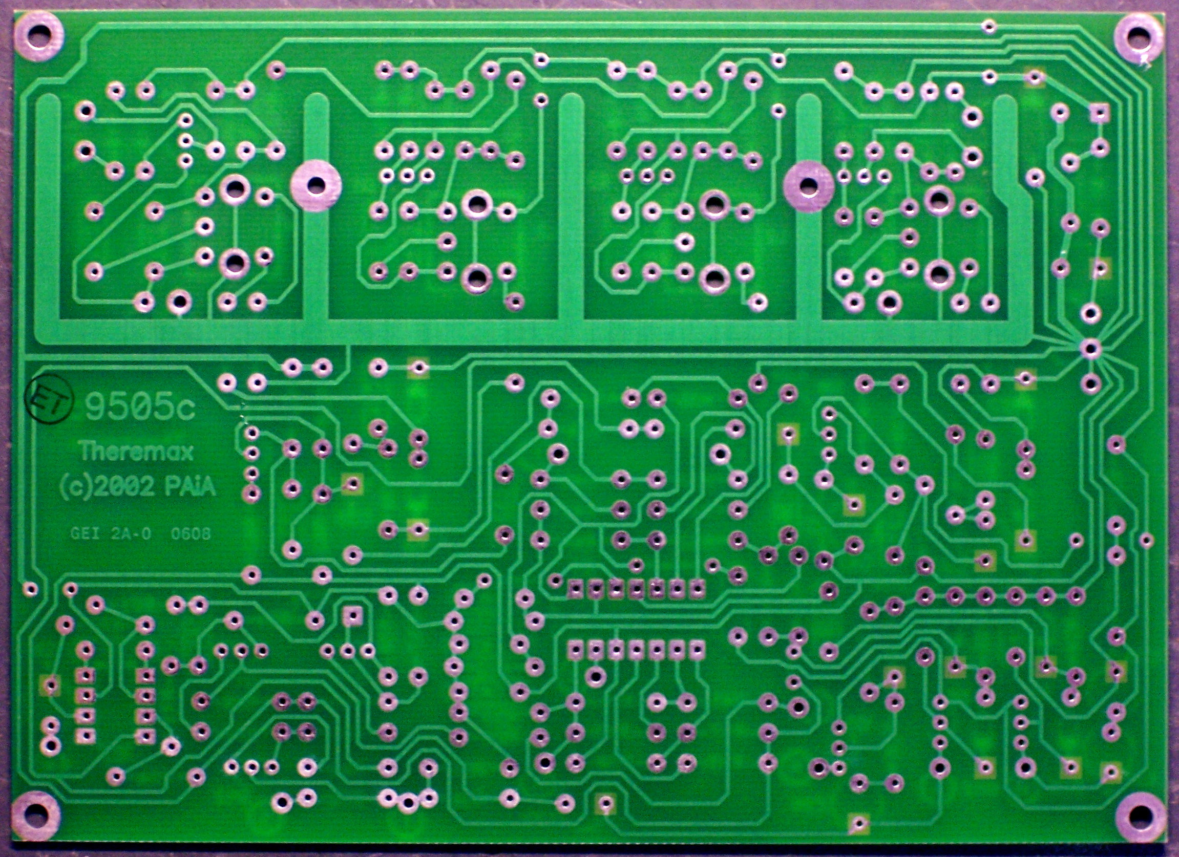
Next, I took a look at the PCB. It’s a nicely-made single-sided board, with silk-screening on the top side for component identification only. I have only two small complaints:
- The identifying marks for resistors and capacitors are under the component, so they’re no longer visible once the component is installed. I know there’s not a lot of extra room on the board for labels outside of the component footprint, but having to refer to a separate parts placement diagram really makes troubleshooting more difficult.
- The resistors and capacitors are roughly numbered from upper left to lower right; but some of the numbers stray across the board, making it hard to locate the correct part. Maybe I’m too picky, but I really like an orderly numbering system during the assembly and troubleshooting stages.
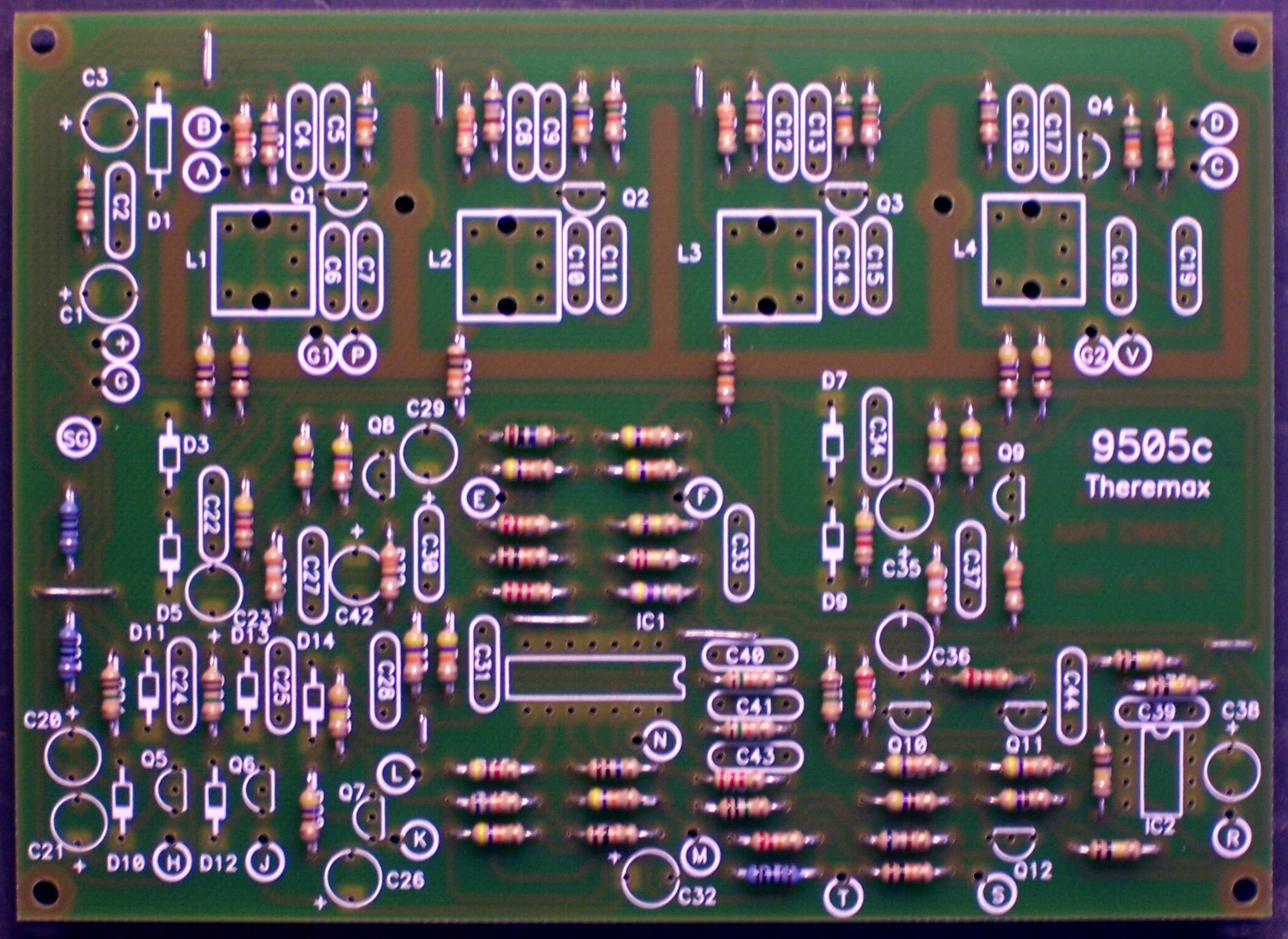
The assembly instructions give a reasonable order for soldering in the components, which I mostly followed–jumper wires and resistors first,

then diodes. Note the blue diodes near the center of the board–germanium, with a lower voltage drop for increased sensitivity. I’ve read a nice description of how that aids the Theremin circuit, although I don’t recall it at the moment.
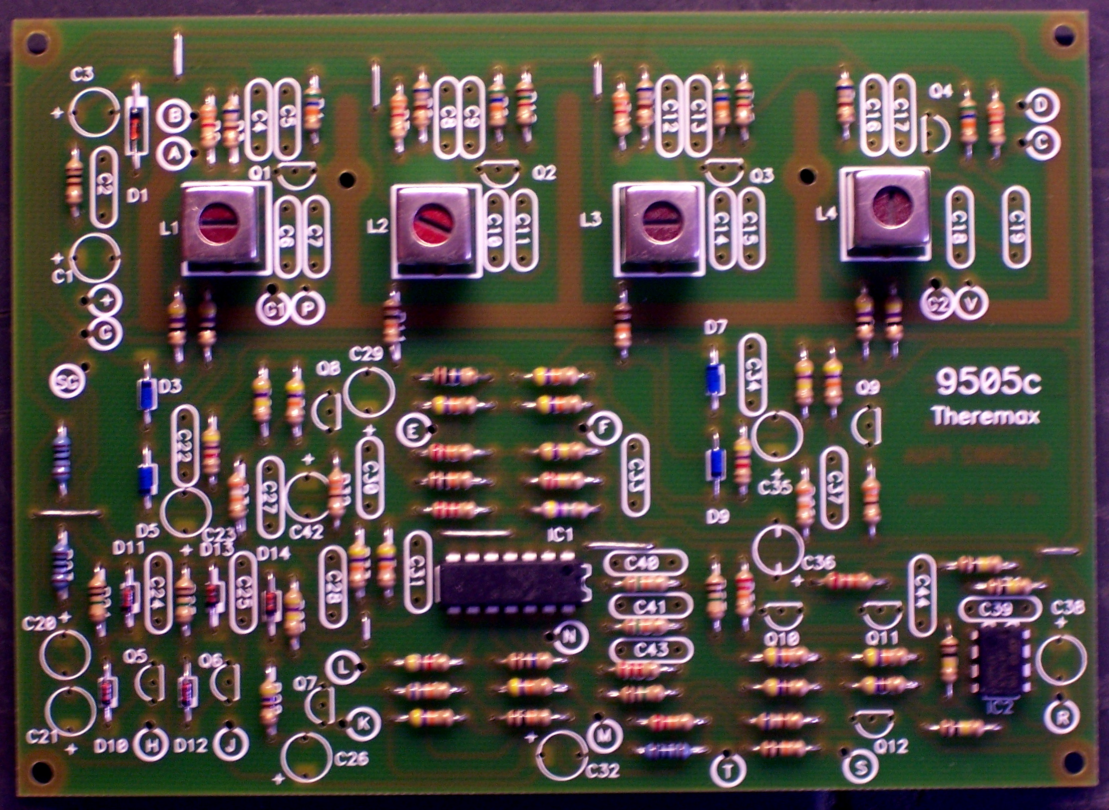
Here I deviated slightly from the instructions’ assembly order, and installed the ICs and inductors next. Because I don’t have a cool PCB holder, I solder with the board upside down on my workbench; and because of that, I prefer to install the shortest components first and work up to the tallest,
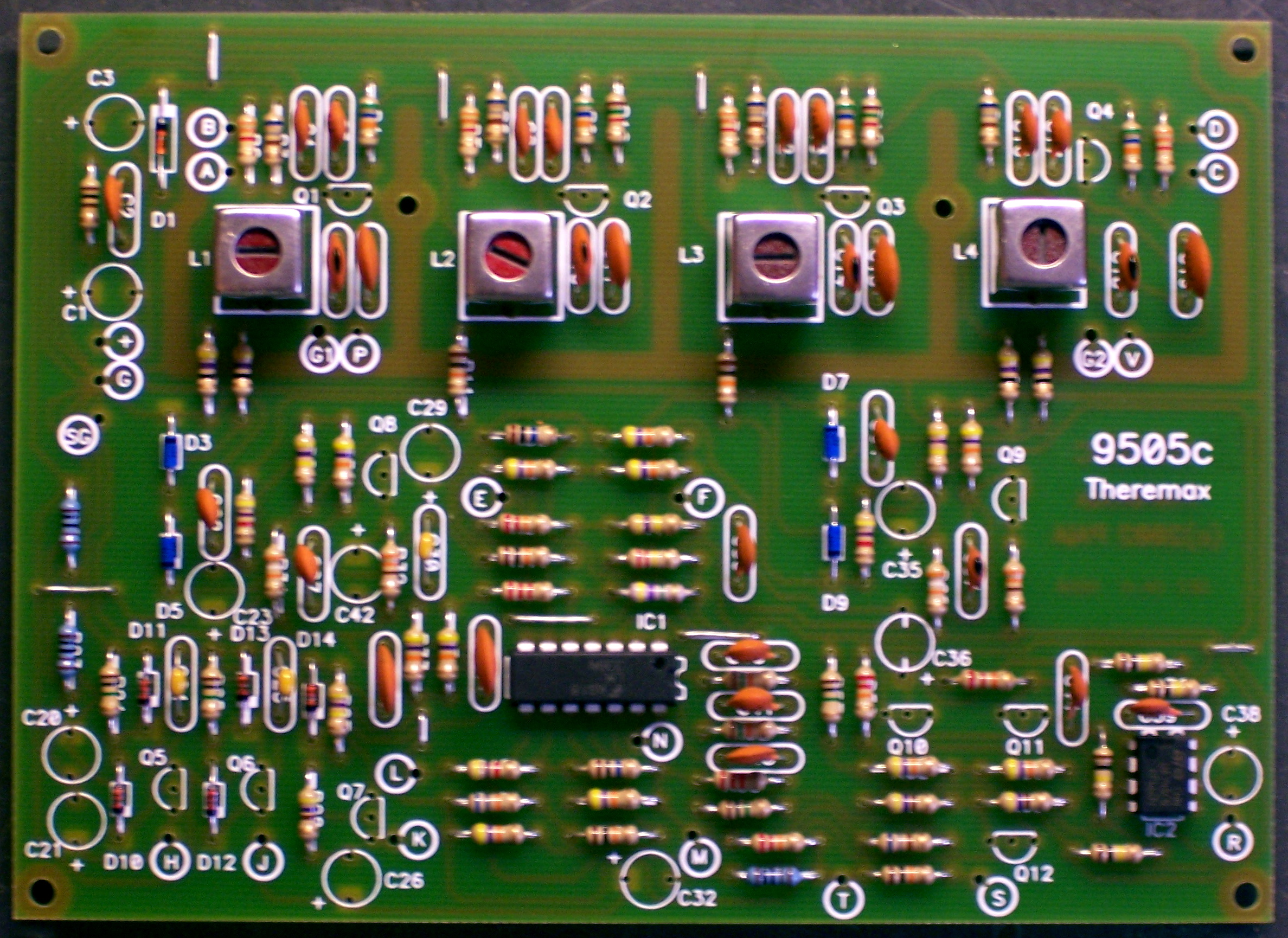
which means doing the inductors before the ceramic capacitors,
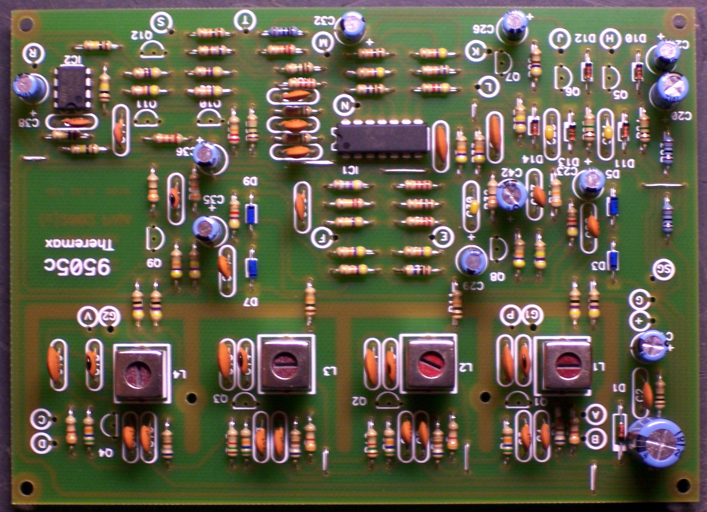
and the electrolytic capacitors last.
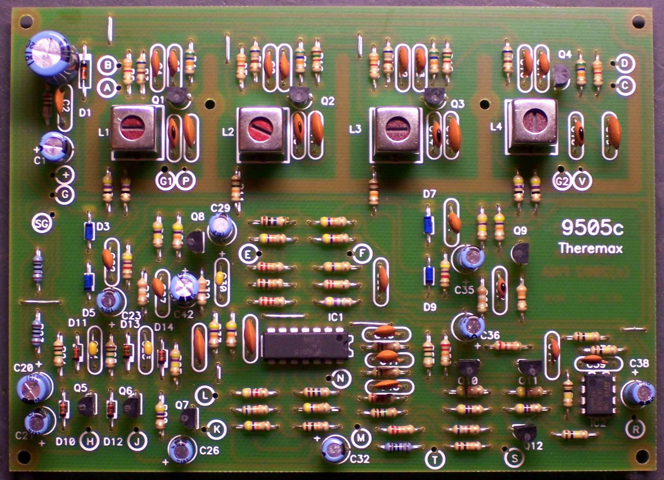
The transistors are actually shorter than the electrolytics, but they cling to the board pretty well, thanks to the hole spacing being considerably wider than their lead spacing.
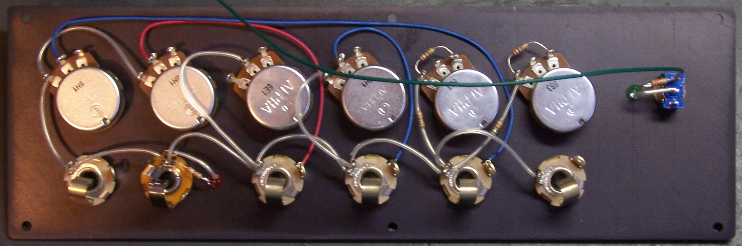
Control Panel
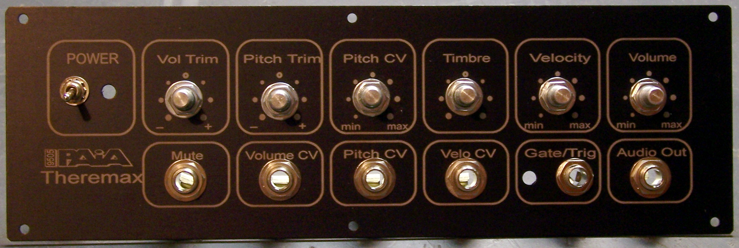
PAiA’s professionalism really shines here, and my photo doesn’t do it justice. This is a very nicely lettered control panel, as good as those on most of the equipment I own. I like the retro feel of the white paint on black brushed aluminum, rather than some glitzy decals on colored plastic that you might see these days.

I installed all of the potentiometers and jacks, twisting them as needed to try to get the hex nuts on the front to line up evenly. (I like to use the phrase detail-oriented.)
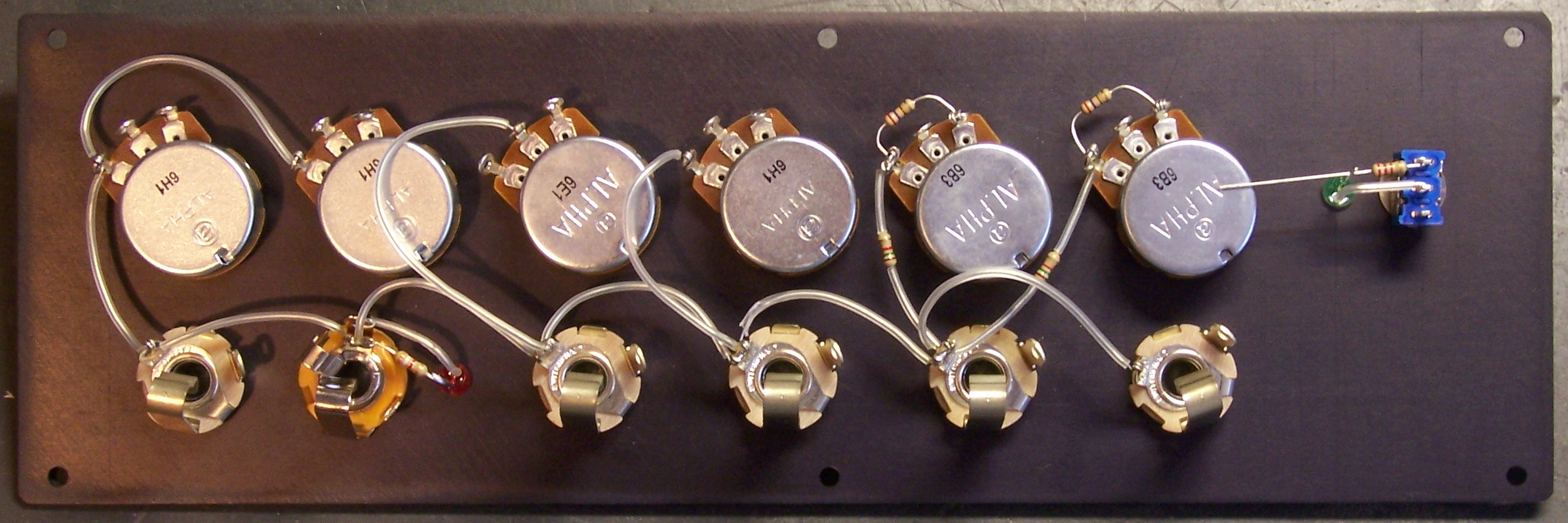
The instructions say to run bare wire from pot to pot for the ground connection; but I’m not wild about bare wire (especially when it has to loop and could be snagged and pulled out to contact something else), so I put some clear heatshrink over it for sleeving. I also built up the LED assemblies–replacing the provided dark red LEDs with my own green LED for the power light, and a matching red LED for the gate trigger indicator.
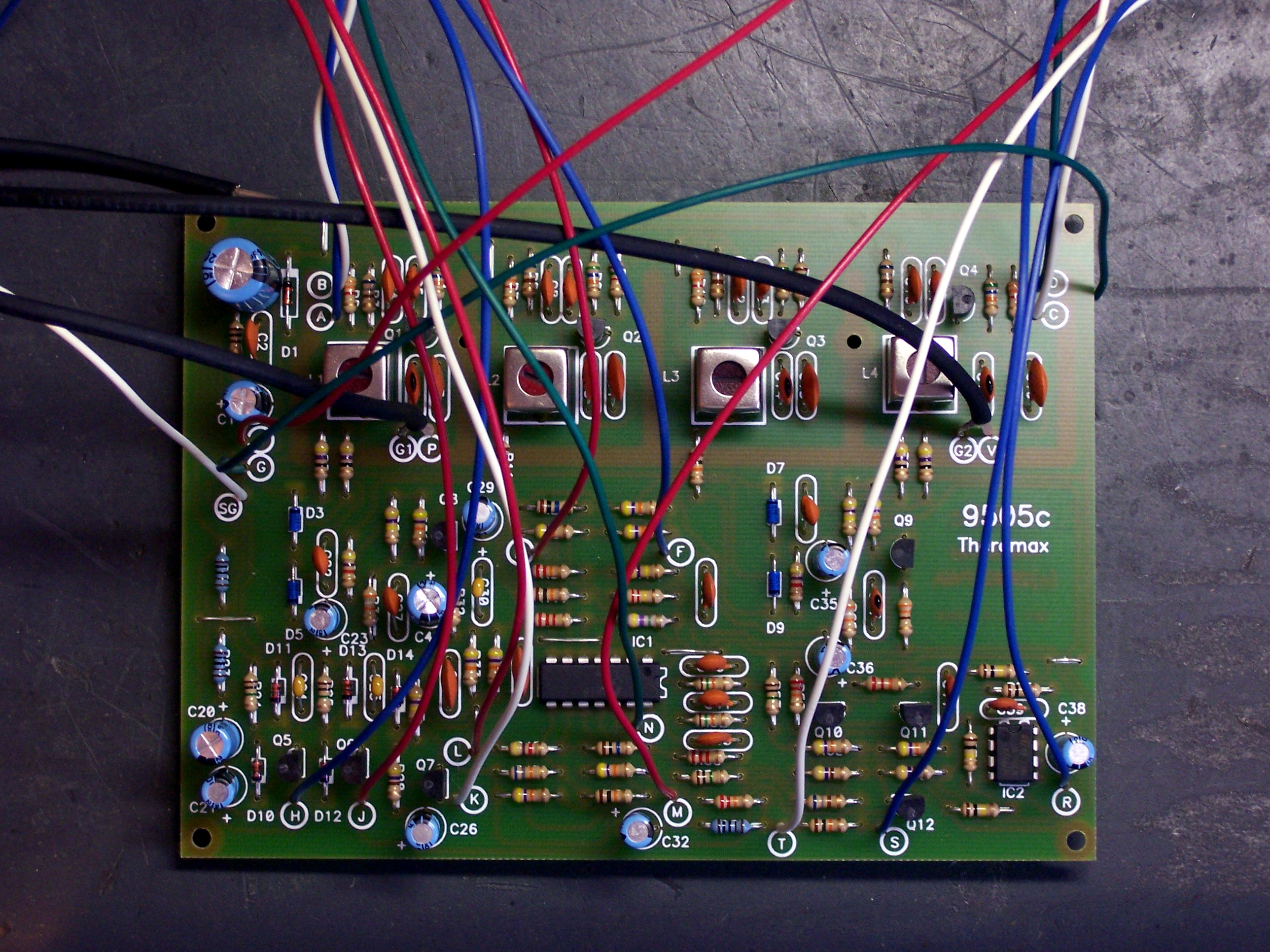
Then I soldered all the fly wires to the PCB. The assembly guide gave very specific lengths; but I think things must have shifted since that was first printed, because the wires had completely different amounts of slack once connected. I shortened some wires and should have lengthened others, and made notes about all the changes I made and further changes I should have made. Here are my notes about the colors I used and the lengths I’d recommend:
| Board | Panel | Signal | Length | Modify | Color |
|---|---|---|---|---|---|
| A | R79-2 | P trim | 9 1/2 | -1 | blue |
| B | R79-3 | P trim + | 9 1/2 | -1 | white |
| C | R80-3 | V trim + | 5 | +1 | white |
| D | R80-2 | V trim | 5 | +1 | green |
| E | R81-3 | timbre short sine | 9 1/2 | red | |
| F | R81-1 | timbre short square | 10 1/2 | -1 | blue |
| G | lug | GND | 10 1/2 | -2? | green |
| H | R82-3 | pitch CV | 12 1/2 | blue | |
| J | R83-3 | volume | 9 1/2 | red | |
| K | R84-3 | velocity | 9 1/2 | +1 | white |
| L | J3-T | velocity CV | 11 | -2 | red |
| M | J2-T | gate | 10 1/2 | -1/2 | red |
| N | J2-R | trigger | 10 1/2 | -1/2 | green |
| R | J1-T | audio out | 12 3/4 | -2 1/4 | blue |
| S | J5-T | volume CV | 16 | -6 | blue |
| T | J6-T | mute | 16 | -5 | white |
| + | S1-1 | +12V | 12 | -1 | red |
| SG | J1-S | SGND | 5 | +1 | white |
| lug | S1-3 | GND | 10 | green |
The last thing I did in that batch of soldering was run signal wires within the back of the panel. The instructions gave this step at the same time as the ground wiring, but I wanted to wait until I had the fly wires chosen so I could maintain the same color wire everywhere a signal traveled.
Next Steps
By now, I’ve connected the fly wires to the control panel, built a case, and semi-mounted the kit in the case. I’ll post those pictures soon.
Hey, your photos and hints on the Theremax assembly are a great help! But I only find Part I. Have you posted more?
I haven’t started on the T-max electronics yet–working on the case first. But in looking at Fred Nachbaur’s T-max at
http://www.dogstar.dantimax.dk/theremin/mytherem.htm
and comparing it to your photos, I noticed two things. For one, he seems to have connected the fly wires from *underneath,* which certainly looks very neat, although it seems it might be a bit tricky to solder. I also note his additional shielding about the oscilllators using unetched PC circuit board, which sounds like a useful modification, but I wonder if there is really enough room to slip it in there without shorting anything out. Maybe with the fly wires underneath? I thought of putting four of the resistors on the underside rather than the topside to make more room, but since he says he puts shielding on *both* sides of the board, that wouldn’t seem to help any. Do you have any observations on these things? (BTW, the standoffs I have on hand are longer than the ones in the complete T-max kit–nearly an inch, so there will be plenty of room underneath the board.)
TIA
Alan Barbour
More on Fred Nachbaur’s extra shielding–I just realized he seems to have put the non-metallic side of the PC board towards the resistors close to and pointing towards the oscillators–so shorting them out shouldn’t be a problem. (A bit of hot glue over the resistor connections probably wouldn’t hurt…)
Fred is pretty much the ultimate Theremax customizer, so anything I build will never compare to one he’s tricked out.
I haven’t played mine enough to know about the stability of the low bass notes. I assume his shielding can be added to a complete and working unit, so you might want to build yours up and see whether you think you really need it.
As to the fly wires, my Theremax’s case is opaque, so they really don’t show. I do take pride in tidiness, but I’m not quite willing to put the effort into soldering wires onto the back side of the board just for appearance’s sake inside a closed case. Of course, everyone’s entitled to their own preferences.
Your notes on color coding of wires is especially helpful. I couldn’t find anything reflecting which color each wire should be in the manual. perhaps I’m not reading it carefully or am just too much of a noob to know what the hell I’m doing.
Tom, I don’t think the manual gives recommended colors — I know I made up the color coding myself. If it’s not standardized across all Theremaxes in the world then it doesn’t really matter what colors you use — but it’s nice to have a record of what you did if you ever need to troubleshoot. I’m glad if my list was helpful.
Were the recommended lengths still a poor match for the actual layout?
Can you tell me more about the parts used? Capacitor size, IC, Transistor and coil can?
Thank You
Poor Man
Fred, the complete schematic and parts list are available in the article “Build this Theremin” in the February, 1996 issue of Electronics Now magazine. It would take me longer to gather and post all the information than it would take you to track down a library that has a copy in their catalog, and you’ll get far more information with the article as well.
Note that I belive it was a two-part (two-month) article, so you’ll probably want the March issue also.
Hello Keith.
I like your blog! A Theremax builder emailed with a question as to the color selection for the wiring steps. I replied that it does not matter, but that rotating through the colors for each step make it easier to trace if it’s necessary to look for trouble. The person replied with the link to your site and in looking it over I see that you had noted the colors and this is great and makes it even easier to trace, but also I see that you changed the wire lengths. They’re specified so they can be dressed without making the run from the panel to the board and crossing near or laying against the parts in the rf oscillator circuits. This is something that needs to make it to a manual update. Until then, if you email me I’ll reply with tips/suggestions which include an image for the wiring. There’s also a mention of changing three capacitors to 100pF (Cs 39 44 and 37) and adding a 6800ohm on R81-3 to R81-2 for improved Timbre control waves and hand-to-volume-antenna-control-response.
Thanks. –Scott
I’m about to begin construction of my T-max and think your tips will be helpful. I like the consistent wire color idea.
Thanks.