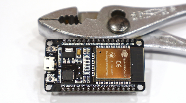
Back in 2021 I documented the process of installing and selecting support for a particular ESP8266 into the Arduino IDE, in case it would help anyone else and as a reference for the next time I needed to do it myself. Well, here I am back again doing the same to bootstrap myself on the ESP-WROOM-32 aka ESP32-WROOM-32.
My refresher on the basics came from https://samueladesola.medium.com/how-to-set-up-esp32-wroom-32-b2100060470c, although he had to go through some steps I didn’t and vice-versa.

First, go to File / Preferences / Additional boards manager URLs and add
https://dl.espressif.com/dl/package_esp32_index.json to indicate another repository to search for board definitions.
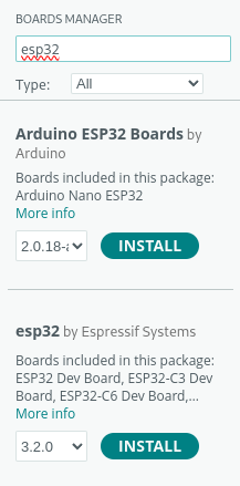
Then Tools / Board / Boards Manager... to pick an available board bundle, start typing esp32, and click to install esp32 by Espressif Systems .
I’m installing this on my Linux workstation so I had to give myself permission to access the USB port, which was:
sudo usermod -aG dialout neufeld
To make that group change take effect, I was only supposed to need to logout; but doing so added me to the entry in /etc/group but didn’t activate the group membership when I ran id or tried to access the device file. I had an OS update to apply anyway so I rebooted and all was well.
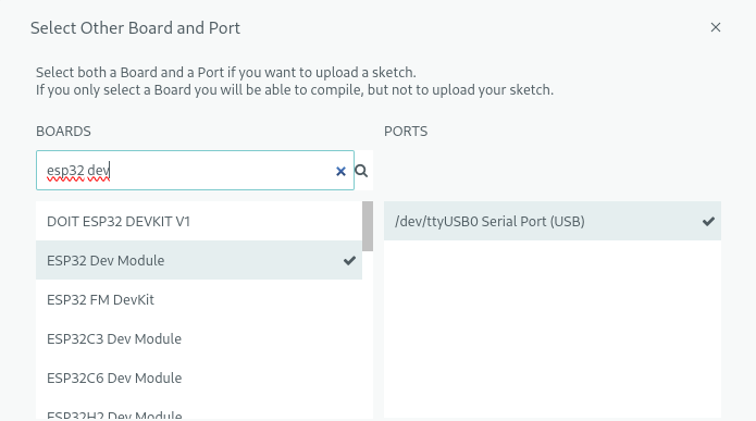
Back in the Arduino IDE, Select Other Board and Port, start typing esp32 dev into the board search, and pick ESP32 Dev Module when it popped up.
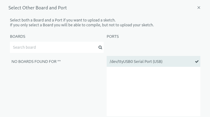
Weirdly, even with the USB serial port selected (and accessible), it complains that no boards were found — but it works.
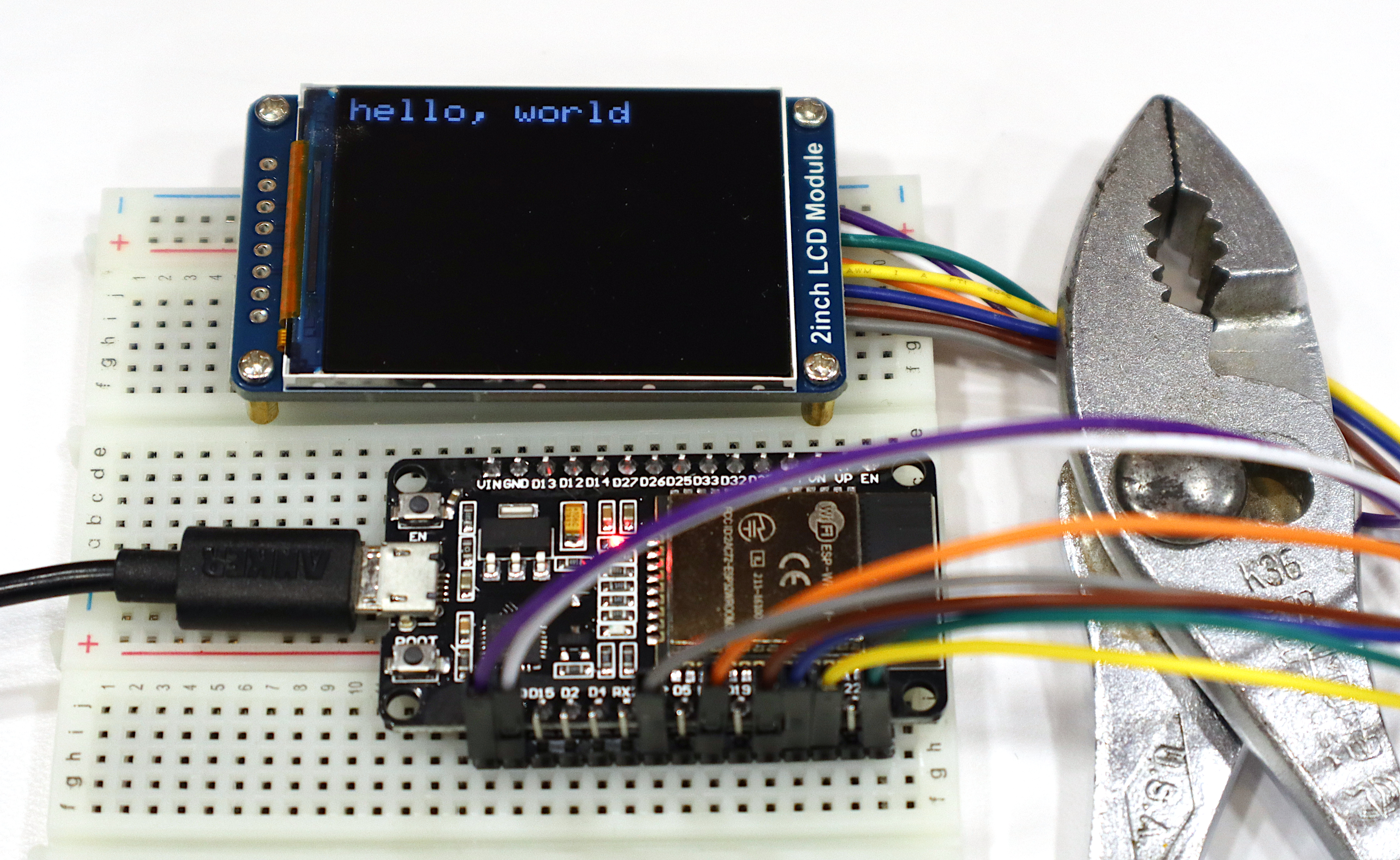
Finally, File / Examples / 01.Basics / Blink to make sure I can compile and upload code to the correct board.
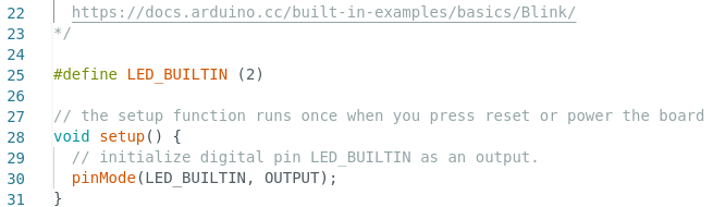
Blink relies on an LED_BUILTIN macro that’s not defined in this Espressif board spec. This forum post suggested pin 2 for the built-in LED on this board and adding
#define LED_BUILTIN (2)
did the trick. Compile, upload, and I have a blinking blue LED next to the red power LED.