Archive for November, 2008

eBay “Misprinted” a Coupon and Won’t Honor Terms

Tuesday, November 18th, 2008

Not electronics; but it’s chic these days to dis on eBay, and hey, it’s my blog.

Just won an auction last night for another SAE A502 amp for $200 + $40 shipping (and that shipping cost is legit — every A502 I’ve bought has cost the same amount to ship), so it seemed like a perfect time to use my 10% off + free shipping coupon.

eBay coupon for 10% off plus free shipping

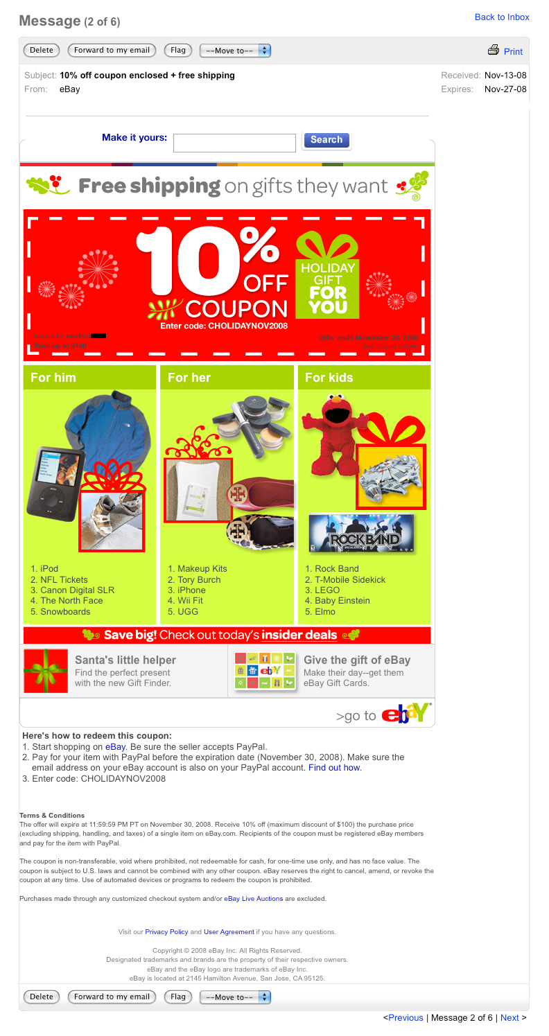
Except when I entered the coupon code on the checkout page, it didn’t take off the shipping. A close examination of the fine print shows that it doesn’t say anything about free shipping — but there it is in big letters at the top of the page!

Hm.

Transcript of my live eBay chat:

System
Initial Question/Comment: Other

08:52:47 SystemSystem
Thank you for contacting eBay Live Help!

08:52:47 SystemSystem
Please hold for the next available Live Help Agent.

08:53:32 SystemSystem
Mark L. has joined this session!

08:53:32 SystemSystem
Connected with Mark L.

08:53:32 AgentMark L.
Hello, thanks for waiting and welcome to eBay Live Help! My name is Mark. How may I help you?

08:54:24 Customerneufeld****
Hi! I got a message in my inbox that says “10% off coupon enclosed + free shipping.” I tried using the coupon last night to pay for an item I won, and it took 10% off the purchase price, but it didn’t adjust for free shipping. Could you clarify how that’s supposed to work?

08:54:42 AgentMark L.
Sure, I will help you with that.

08:55:32 AgentMark L.
Are you referring to the coupon that states 10% off on shipping from the purchase price?

08:56:30 Customerneufeld****
Well, I’m not sure how to describe it, other than to type in everything that’s on the coupon and in the text below. Is there any way you can look at what’s in my inbox?

08:57:18 Customerneufeld****
The graphical part of the coupon says “Free shipping on gifts they want,” then down below it says 10% off the purchase price of a single item. The coupon code is CHOLIDAYNOV2008.

08:57:48 AgentMark L.
I am sorry but that it was a mis-print on the coupon. We will be sending a new message to you that will state that the coupon had a mis-print and there was no discount on the shipping.

08:58:49 Customerneufeld****
That sounds an awful lot like false advertising to me — you can retroactively change something like that and not get in trouble?

08:59:07 AgentMark L.
I do understand that this can be upsetting.

08:59:42 Customerneufeld****
I’m just curious.

09:00:13 AgentMark L.
Have you already paid for the item?

09:00:17 Customerneufeld****
I mean, eBay is the 800-lb gorilla of online sales, and I recognize that I alone can’t change what you decided to do. But I’m honestly curious if that doesn’t fall under false advertising law.

09:00:43 Customerneufeld****
Haven’t paid yet — I contacted the seller and said I had a question about how to use a coupon, and I’d be back in touch with him today. He said no problem.

09:00:57 AgentMark L.
I am very sorry that you have to go through this.

09:01:13 AgentMark L.
However, the coupon will not be applied to get the free shipping on the item.

neufeld****
Well, that’s what I needed to know.

09:02:00 AgentMark L.
There is no need to worry about. We send several coupons on a random basis and I am confident that you will receive anther one so that you can enjoy the benefits of the coupon for your next purchase.

Obviously if eBay makes up it’s mind that it’s going to do something — legal or not — it takes more than one person to get them to change their mind. But at least I can have a little fun with the agent along the way.

X-Ray Control Panel???

Sunday, November 16th, 2008

One of the electricians at work gave me a bunch of circuit boards from decommissioned equipment this week. It’s usually elevator stuff, so I hadn’t paid much attention to it other than to note the pretty colored wires.

XG controller panel, rear

The I was taking it out of my trunk to put into a “process later” pile when I noticed the front.

XG controller panel, front

“X-Ray.” 60kV tube voltage. “Fine focus.” Whaaaa???

Combined with the way all the front-panel switches and knobs are bent and broken off, I’m guessing this was in one of the laboratories, some unfortunate researcher accidentally stepped in front of the beam and mutated into a creature with superhuman strength, and in the resulting chaos demolished the equipment. Since it was destroyed, now I have it. Cool!

I went ahead and disassembled it tonight. Here’s a different view of the meters:

Edge-style panel meters

And there’s a big pile of connectors, resistors, and lovely wires on my workbench.

Cool Rotary Switches

Here are the two rotary switch assemblies. Their knobs were broken off and their shafts bent, so they’re not working terribly well, but I’ve improved them a little.

Rotary multi-position switches

They have circuit boards that are ganged together, with the inner shaft turning the back set of switches (of course) and the outer shaft turning the front set.

Rotary multi-position switches

The mechanics of the assemblies are fairly intricate. You can click the picture (as always) for the full-resolution version if you want to follow along.

Rotary multi-position switches, partially disassembled

Clockwise from the bottom:

Every switch position is a separate trace on the PCBs, with 24 positions on the wide assembly, 12 positions on the rear part of the narrow assembly, and two sets of 5 positions on the front part of the narrow assembly. A wiper on the plastic rotor connects the PCB’s inner ring trace to each outer pad in turn.

In the upper left, you can see how the limits of rotation are set by two discs with tabs sticking out, which bolt onto the head end of the (sub-)shaft. The discs’ tabs stop against a rear-pointing tab on the head-end mounting plate, which is on the underside in this picture.

Shown at the top, the rear portion of the narrow assembly is still in good condition. It was pretty gummed up, but a few sprays of silicone lubricant got it turning nicely. The PCBs are mounted on a set of multiple threaded rods, threaded spacers, and unthreaded spacers. The rotor’s detent action is provided by the wavy disc on the back side of the mounting plate, a ball bearing sitting in a hole in the plate, and a leaf spring on the front side of the plate.

In the upper right, the front portion of the narrow assembly is okay, but the outer shaft that used to rotate it was sheared off at the base (shown immediately below it).

I had to saw the front knob off the narrow assembly’s shaft to get the assembly apart and make part of it usable. You can see that the kob appears to have been threaded onto the end of the shaft; but with a vise and a pliers, I was unable to turn it loose. The shaft had been pretty badly bent anyway, so I have no hard feelings about having to saw it off.

Idea for Rotary Switches

So I’ve actually been looking for rotary switches like this, and thinking of trying to make some myself. This unfortunately is not the form factor I need, but it shows the idea is sound.

The high school robotics team has strict rules they have to play by, and one of them is that the joysticks used to control the robots in non-autonomous mode must work like PC joysticks (I think the PIC that runs their control panel is charging and timing an RC circuit to determine the joystick position) and cannot have any supplemental power.

This wouldn’t matter, except that the linearity of the joysticks they have is poor; and with (apparently) only 8-bit sampling, there’s not as much they can do programmatically to correct the linearity as they’d like. So it takes a bit of programming effort to eliminate drift when the stick is physically centered; and then when they start to move the stick, the robot lurches into action with not much fine control over low speeds, and at high speeds is pretty much just maxed out.

Of course I assume if it were my robot, I could correct most of that in programming. :-) Still, that’s a lot to ask of high-school kids who are already making amazing engineering accomplishments on a very tight timeline.

So Ron (of the fundraising concert, and father of the team captain) would like to figure out how to build a new joystick that abides by the letter and spirit of the rules but gives finer control over low speeds and has really significant jumps up to maximum speed only when you floor it. Obviously he wants pots with an S curve response (log taper in both directions from center), and he hasn’t been able to find that commercially, at least not that he could retrofit into a joystick.

His idea was to do it discretely — come up with some sort of switching action, then connect that to a resistor ladder. He could play with the resistor ladder to his heart’s content until he got something that “felt” right for the application — make it pluggable and let the kids swap resistors until they got a response curve they liked. And he wasn’t too worried about the robot lurching as the joystick went from step to step on the ladder — he feels that relatively few values would suffice.

If these 24-position rotary switches could fit into a joystick’s gimbal assembly, they’d be fantastic for that! Reserve the middle 3-4 positions for a broad center band to eliminate home-position drift, then have ten more positions in each direction for different speeds.

Except I’m pretty sure the gimbal assembly has little 3/4″-diameter pots right there on it, and these big PCB things just wouldn’t work. Feh.

I thought about etching my own PCBs to replace the wafers inside a couple of sacrificial pots, but I hadn’t figured out quite how to route all the wires out.

Open to suggestions here.

Radio and Video Stuff and Projects in Progress from Slim

Sunday, November 16th, 2008

Last weekend, Lawrence and I went to Pittsburg to help Maeve clean almost the last of Slim’s stuff out the garage. Here are some of the first interesting items from the vanload we brought back. Some of this I’m keeping; some I’d love to place in a good home.

SWR and Power Meter

This is going to Cort.

Comet CD-270D SWR & Power Meter, front

Comet CD-270D SWR & Power Meter, rear

He writes:

I’d like the Comet SWR/Power meter… Yes, I have a MUCH MUCH better one now… But that was the one Slim and I did ALL of the early repeater stuff with. There’s a lot of sentimental value attached to it. I was having a HELL of a time trying to get reasonable readings. He showed up with that one day and it made life so much easier. It was one of those “gold standard” items for us for a number of years.

Antenna

Don’t know what kind, but that’s an F connector on the bottom. Yours if you want it — any offer that includes shipping cost will be accepted.

Antenna

TrunkLine Millenium Active Headend Combiner 95-AHC16

This combiner takes CATV signals that are already RF modulated and merges them onto a single feed. I believe this had never even been opened until I took these pics. Available claimed.

TrunkLine Millenium 95-AHC16 active headend combiner in box

TrunkLine Millenium 95-AHC16 active headend combiner, front

TrunkLine Millenium 95-AHC16 active headend combiner, upper rear

Datavideo Timebase Corrector

A card to go in a PC — as far as I can tell not even connecting to the bus for anything but power — to stabilize video sync before capture. By my estimation, a relic of bygone days, and available upon request claimed.

datavideo timebase corrector

Vidicon Tubes

Although I’d never actually seen them before, I recognized these pretty quickly as videocamera imaging tubes, and the labelling identifies them as Vidicon.

Box of Vidicon camera tubes

RCA 7735B Vidicon camera tube, side

RCA 7735B Vidicon camera tube, front

Available if there’s any interest:

Qty Condition Description
2 apparently new in plastic case RCA 7735B
2 not visibly damaged RCA 7735B in GE box
1 visibly worn but not visibly damaged RCA K1008 in GE styrofoam claimed
2 unopened 2AP1 in soft paper
Probably a CRT — keeping
1 unopened “2AP5 BLUE” in soft paper
Probably a CRT — keeping
1 unopened WA0EDA (?) in soft paper
1 “Was burnt in place (useable) [sic] Matsushita S4097 claimed
1 “Used / beam current varies” Hitachi 7735A used in box
1 face shattered RCA 7735A, loose
1 face edge cracked, something loose inside Ampex 4508, loose claimed

Speaker in Swivel-Mount Enclosure

Speaker in swivel-mount enclosure

Perfect prop for the next Brazil.

Slim’s Portable Powered Speaker

This is a cute little Slim-built powered speaker. That appears to be a PL-259 plug with the tip broken off on the front — I’m not sure what the logic was behind using that connector. I’m thinking I should replace the connector and hang this on the wall above the workbench.

Slim's portable powered speaker, front

Inside, a 9V battery clip and audio amp module.

Slim's portable powered speaker, interior

Glass Heating Plates

This looks like some kind of experiment. Electrically-heated glass plates, half assembled. Slim was very interested in optimizing PCB production; maybe this was a test for heating etchant? Maeve takes hot tea and was always looking for a way to keep the pot warm; maybe this was a test for a teapot pad?

Glass heating pad, front and back

Glass heating pad, backlit

HeathKit Programmable Wind Chimes

I just missed the HeathKit era and never had the opportunity to assemble one (although I have of course assembled other electronics from kits, just not HeathKit). Here’s an electronic “wind chime,” complete and completely unassembled. Wow.

HeathKit TD-1089 programmable wind chimes, unassembled

HeathKit TD-1089 programmable wind chimes assembly guide

I’m torn between the opportunity to finally build a HeathKit, and the desire to preserve this forever just as it is. :-)

Indicator Light Bezel

I love this! Wish I’d found more of them, but so far only the one. Er, two. Well, the one bezel that’s a two.

Lensed 2 bezel, front

Lensed 2 bezel, side

Lensed 2 bezel, lit

Salvaging a Pile of VCRs

Monday, November 10th, 2008

VCR mechanics, PCB, and wiring harnesses

A few weeks ago, I tore into a stack of dead VCRs, salvaging interesting parts, recycling a lot of metal and plastic, and intending to reduce the volume they consumed. Unfortunately, the resulting lesser volume has been mounded up on my workbench instead of neatly stacked in the garage.

The insides of VCRs are familiar to most tinkerers, but some of the bits are more interesting in bulk.

(more…)

Edge-Lit Plexiglas Demo

Thursday, November 6th, 2008

11-Nov-2008

Welcome, Make and Gizmodo readers! I didn’t expect this kind of attention; but you mention light sabers, I guess geeks like us are bound to get excited. :-)

This was meant to be a crude, quick proof-of-concept prototype, and at that it succeeded. I now have 500 white SMT LEDs on the way from Hong Kong; and when they arrive, they’ll each — grain of rice sized — get glued to the end of a piece of plexi, where they’ll be nearly invisible when off. It’s up to Lisa whether the connecting wires will be visible or minimal; and bless her heart, she says she wants to incorporate visible wires into this piece, so I don’t have to mess with 1000 hair-thin, enamel-coated wires.

Finally, this is only good for artistic purposes or accent lighting. As you may have noticed when shopping for LED light-bulb replacements, there’s very little out there even close to the brightness of incandescents. If you want to light a hallway as you walk through, I’d suggest Piranha (bright) or Luxeon (brighter) LEDs in the baseboards and an ultrasonic rangefinder at the end of the hallway to determine your position.


Edge-lit plexiglas strip in LED tester

I have the privilege of working with Lisa Rundstrom on an art installation for a show at the end of November. Lisa does amazing work with plastic (especially acrylic) and light (really, go look at her site), and we’re planning a cloud of 200+ hanging acrylic pieces, edge-lit with white LEDs, interacting with audience members.

If I don’t descend into gibbering madness from the impending deadline, the piece is going to be amazing. (If I do descend into gibbering madness, I expect that’ll be amazing too.)

Our art / technology / education collective has been meeting once a week in preparation for the show, and last night I built a little demo to give a rough idea of what controlled LEDs could look like.

(more…)

(Not) Fixing a Zoom Studio 1201 Effects Unit

Monday, November 3rd, 2008

Zoom Studio 1201 effects unit

I recently bought an allegedly-broken rackmount audio effects processor on eBay, described by the seller thusly:

ZOOM STUDIO 1201

DIGITAL REVERB & MULTI EFFECTS

Powers On but no sound on output

It sounded like an interesting problem — maybe a bad jack or pot, or of course possibly a bad DSP or custom chip that I wouldn’t be able to fix — but worth $10 plus shipping to give it a shot. I was the only bidder; and after a long delay (one of the advertised features of the unit, but not one I expected from the seller) it was mine.

The first thing I noticed is that it did not, in fact, power on. The minimal instruction sheet says that the Peak LED goes green to indicate power and red to indicate peak / clipping; and mine remained off. So the unit did not, in any sense in which I’m familiar with the term, “power on.”

I checked the wall wart, thinking it might be faulty. It appears not to be the original power supply for this unit (see the verbiage at the bottom of the label — not, to my knowledge, synonymous with “audio effects processor”), but did deliver 9VDC.

9VDC wall wart supplied with Zoom Studio 1201 effects unit

Ah, but not the right 9VDC.

Zoom Studio 1201 power jack

The replacement power supply had the wrong polarity. Thus I was even more puzzled as to in what sense this unit could have been considered to “power on,” unless the seller had the correct power supply while posting the unit for sale but delivered a different one.

I checked my wall wart bin but didn’t have a suitable replacement. So for testing, I used a few jumper wires and a passive auto power adapter with the same barrel connector to reverse the polarity:

Powering Zoom Studio 1201 with wrong wall wart and jumper wires

And voila! Green power light. Maybe “powers on” means “with considerable effort.”

Having tested that it was worth the trouble — that the unit hadn’t been completely blown by reversed polarity — I cut and soldered the wall wart’s cable back together to deliver the correct polarity for this unit. (Mental note: I forgot to update the diagram on the wall wart — need to go back and do that.)

I took it to my synth and inserted it between the synth and powered speaker to test whether “powers on” now equated to “works completely,” and alas, it did not. The input trim pot works and impacts the output volume; the output volume control works and impacts the output volume; but no other controls have any effect. It’s as though I’m constantly getting a “dry” mix.

Zoom Studio 1201 PCB

I tested the wet/dry pot in circuit, and it does vary resistance continuously over its range, so it doesn’t appear to be the problem. I tested the foot pedal effects override jack with both my meter and a spare plug, and it doesn’t appear to be faulty — and the instruction sheet says disabling effects with the foot switch will make the Peak light will go amber, which isn’t happening. I touched up the solder joints on one of the effect selector switches, and no difference. Still the “dry” sound coming straight through to the output.

Particularly puzzling to me is that the Reverb Effects selector (which is a pot with detents rather than a position encoder — evidently an A/D input was cheaper than four digital inputs) causes a brief dropout of output as it’s rotated between positions; so something appears to be talking through the digital guts of the beast. But no matter the setting, I still get the dry output.

I should note that the effects bank selector switch, although physically broken, is still electrically functional — moving it to the different positions with a small screwdriver does provide continuity among different sets of contacts on the back.

I realize now that I’ve only been testing the left channel so far, as it doubles as the mono channel. I should try testing the right channel in case something in the signal path is only broken on the left.

Anyway, at the moment I differ slightly with the seller: powers on when you hook it up right, original sound on output, but no effects.