Archive for the ‘Repairs’ Category

Fussing with My Server Power Supply

Saturday, November 13th, 2021

This wretched miserable piece of notworkingness has been causing me a fair bit of grief in the last couple of weeks.

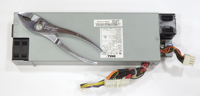
Dell Poweredge 750 server power supply

This is the power supply from the Dell Poweredge 750 (yes, that’s 750, not R750) server from which, if it is still near the year 2021, you are being served this web page. A couple of weeks ago, it developed the new behavior of powering up perfectly well to start booting the server and start running the BIOS tests and then shutting off again.

Being in a bit of a hurry at the time, I grabbed my spare ATX power supply and hooked it up to get the server running again with the lid open and deal with the original power supply later. But with the new power supply connected, the server wouldn’t boot at all, because

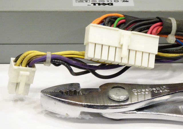
Dell Poweredge 750 server power supply motherboard connectors

what is this??? Oh, for a larff, let’s move the purple 5V standby wire from the ATX mother board connector to the PCI power connector, har har! So with the spare power supply connected, the server wasn’t receiving 5V standby [where it wanted it] to run the On button to turn on the power supply and the server.

(more…)

Replacing a Pollcat Power Supply

Saturday, October 3rd, 2020

Replacing a power supply should not be a noteworthy task; but when an exact replacement for the failed power supply isn’t available, one wants to exercise some care and diligence installing a compatible-but-different power supply.

Shamefully long ago (cue Wham’s delightful “Last Christmas” and sing along to ignore the guilt), one of the two redundant Pollcat telephony call-detail-monitoring gateways at work didn’t recover after datacenter electrical maintenance. Last weekend I finally looked at it, confirmed that the power supply was dead, and confirmed that the rest of the unit operated fine when run from bench power.

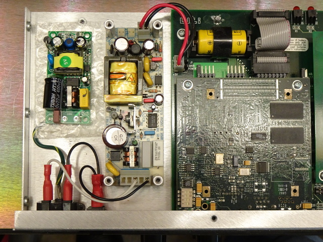
Pollcat shown with new and broken power supplies

I couldn’t find a reasonable source for the original model of power supply (the right of the two, toward the center of the photo); so after a bit of searching came up with different a 5-VDC 2-A open-frame power supply (the left, on some bubble wrap) that can physically fit into the available space in the enclosure and that can also operate from 100-240 VAC (important for datacenter 208 VAC) for a very affordable $10. We ordered a couple of them and I got it replaced this afternoon. I expected from the beginning to have to make a mounting adapter, but I also had to mind the polarity of both the AC and DC power connectors.

(more…)

Subwoofer Voice Coil Failure Modes

Sunday, June 9th, 2013

From the latest batch of reconing:

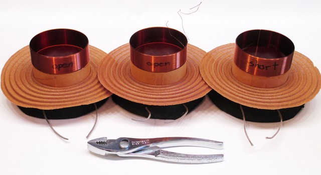
Three broken subwoofer voice coils

The left two are open — you can see the broken wire at the bottom of the left coil and the top of the middle coil. (As always, click for full-sized image.) The right one is shorted and I haven’t found where.

I find it interesting that these are wound with round wire and the replacements are wound with flat-cross-sectioned copper “ribbon,” to get more current capacity in the same vertical space.

$10 Razor E100 Scooter Project Day Two: First Battery-Charging Attempt

Sunday, April 28th, 2013

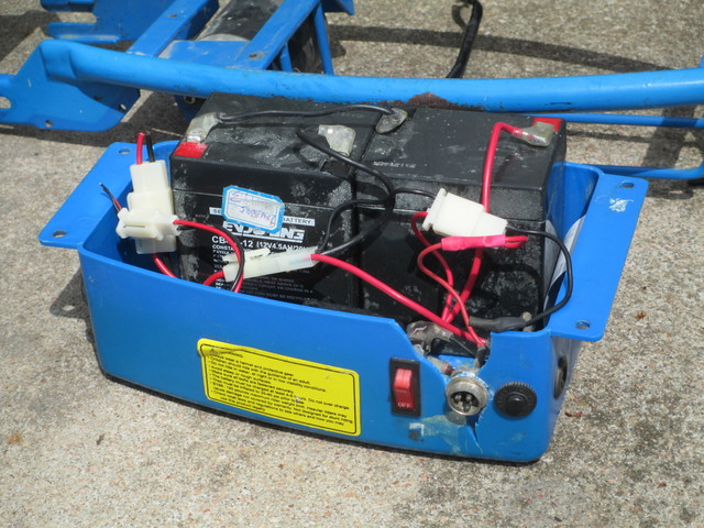
Razor E100 battery and speed-control bucket

I tend to assume that batteries I happen upon will not be charged. Also that lead-acid batteries I happen upon will be low on water, even so-called sealed lead-acid batteries.

I wanted to start charging the batteries from my “new” scooter while working on other aspects of the project and the scooter didn’t come with a charger — I’ll deal with that later. Not knowing much about the wiring circuit yet, I didn’t want to connect an external charger to the batteries while they were still in-circuit and chance damaging the speed controller, so I needed to disconnect and remove them.

Wiggle wiggle wiggle <grunt> wiggle pull <grunt> WIGGLE WIGGLE BEND <grunt>

Wha?

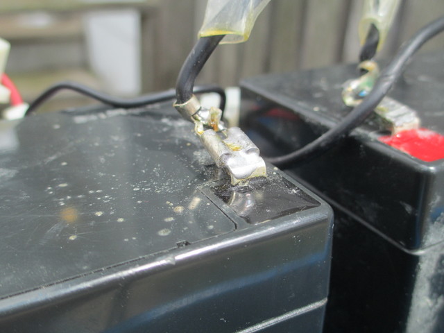
Soldered battery clip

Who does this??? When they said solder the quick-disconnect terminals, they meant the wire side.

Fine. My uncle’s iron and a pair of pliers solved that problem.

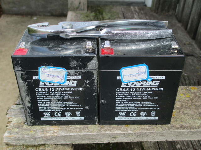
Two sealed lead-acid batteries from Razor E100 scooter

Two batteries, extricated and not yet cleaned.

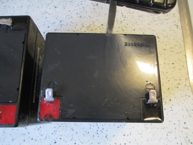
Prying open sealed lead-acid battery cover

In spite of being “sealed,” you can pry off the cover (preferably after cleaning, which I did first with Goo-Gone and then with dish soap and water)

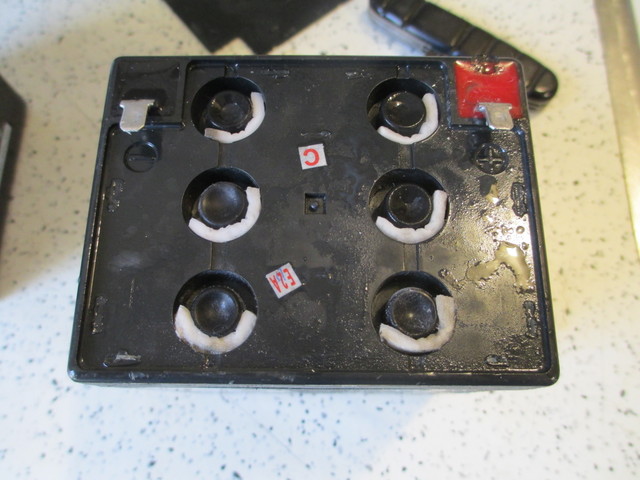
Sealed lead-acid battery cell caps

and get to the cell caps, each with a little absorbent pad in case the cell venting carries too much moisture.

I could see no water in any cell of either battery. I borrowed a jug of distilled water from my folks (I don’t know why Mom always has some, but she does) and started filling them up … after taking measurements.

Battery 1 Battery 2
Initial 11.68 V 9.99 V
After adding water 11.62 V 9.92 V

I filled each cell, waited for air bubbles to trickle to the top, refilled, waited, refilled, waited … I’m guessing between the initial fill and while charging, I ended up putting at least 10 ml of water into each cell.

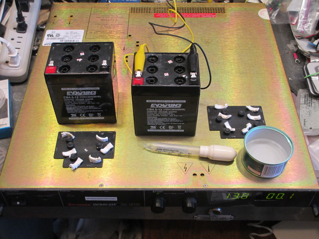
Then put battery 1 on my variable power supply with the voltage set to 13.8 V and the current limited initially to 0.1 A, raising the current limit to 0.3 A as it was clear that nothing horrible was happening. I checked on it every half-hour to hour, frequently refilling at least one cell in which I could no longer see any water.

After about four hours, it was up to 13.5 V. The water level in the cells had risen to overflow the opening and fill each reservoir. If I watched long enough, I could see the water in a couple of cells <pop>, indicating they were just starting to gas and it was time for me to stop this method of charging for the day. (More on that on a subsequent day, hopefully tomorrow.)

Charging sealed lead-acid batteries with power supply

While battery 1 was charging, I was also checking water levels in battery 2 and refilling low cells, just sitting on the counter.

Recalling that it had an initial 10 V charge to battery 1′s 11.7 V, noting that they had been connected in series, and knowing that the worst cell in a battery generally has a cascading failure, I expected a different charging experience from battery 2, and I was quite right.

I connected it to the power supply and it immediately showed 13.8 V at a 0.1-A current draw. Now, about an hour later, it’s at 13.5 V and 0.3 A and most of the cells have overflowed. It’s nearly done charging but I haven’t put nearly as much energy into it as I was able to put into battery 1 — that is to say, it’s not “taking” as much of a charge.

Battery 1 Battery 2
Initial 11.68 V 9.99 V
After adding water 11.62 V 9.92 V
After charging 12.68 V 12.48 V

Tomorrow, schedule willing, a load test and an attempt at desulfation.

$10 Razor E100 Scooter Project Day 1: Rear Wheel

Saturday, April 27th, 2013

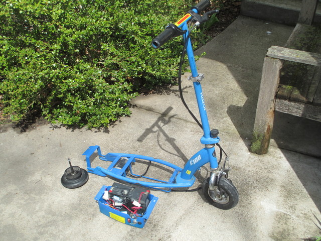
This afternoon I learned of the recently- (?) opened Deja Vu thrift store in Newton and made my first purchase: a Razor E100 scooter in considerable state of disassembly. I’ve long thought that electric scooters looked like fun …

Pieces of Razor E100 electric scooter

All of the wires are cut, the deck is missing, the rear wheel was unattached, naturally the drive belt was missing, and no charger.

$10. I bought it. Sounds like a fun project, eh?

Razor E100 scooter battery compartment

The battery and speed-control bucket could use some repair but seems at least functional. I started working on the batteries but as soon as my brother was available redirected my attention to reattaching the rear wheel.

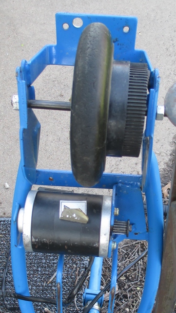
Razor E100 scooter rear wheel, loose in forks

The rear wheel is belt-driven and needs to be positioned to align with the motor pulley but the spacers were absent and it slid freely from side to side.

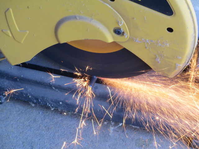
Cutting a roll pin

A trip to the hardware store resulted in a roll pin with ID slightly larger than the 1/4″ axle diameter and length slightly greater than the two spacers needed, for $1.89. Then my brother’s giant chop saw made short work of creating two pieces from one.

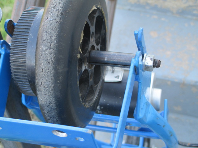
Razor E100 scooter rear wheel, mounted

Touched up a bit on the bench grinder, ends rounded over with a file, and interiors cleaned out with a round file, spacers fit perfectly and the rear wheel bolts on securely. We “kicked” our way up and down the driveway and are eager to get the scooter powered up.

Next: Battery investigation.

Motherboard Electrolytic Capacitor Replacement

Sunday, April 15th, 2012

I’ve been quiet lately because I’ve been too busy … hope to break free of that by mid-May and get back to some projects.

I’ve made time to do a little server work; I’m trying to build a more consistent set and get my servers all up to current OS versions. I have three nice rackmount server cases, and while scrounging ATX motherboards to put into them, I ran across this.

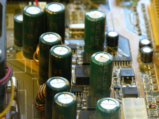
Computer motherboard with bulging electrolyic capacitors

The electrolytic capacitor just to the right of the center of the image is seriously bulging, as is the out-of-focus capacitor behind it. They both test good with the Capacitor Wizard, but I wouldn’t trust either of them with power applied, at least not inside anything I care about. Always at least visually check electrolytics before you power up something that’s been off for a while.

Desoldering was easy — heat both leads and gently rock them out.

Cleaning the solder out of the through-holes was trickier. At least one of the holes was attached to one or more large copper planes and kept sucking away the heat — I had to add solder, keep it preheated with the iron so it stayed liquid through the hole’s whole depth, and quickly slip the solder braid into place. Heating solder braid on top of a topped-off through-hole wicked away the top solder before heating it all the way through.

And then I ran out of solder braid. Ended up drilling out the holes, which I’d wanted to avoid in order to avoid any risk of damaging the plating. But I picked a small enough bit that I didn’t even remove all the solder, and it worked out okay.

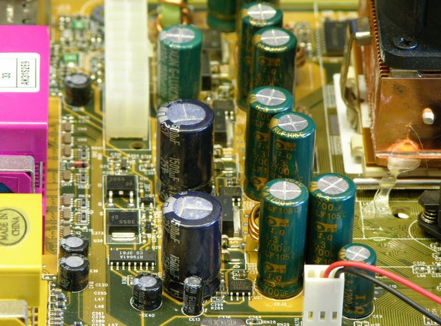
Computer motherboard with replaced electrolytic capacitors

The replacement capacitors I had on hand were a little wider and crowd adjacent components, but at least are rated for 105°C like the originals. And they seem to work; the board is now cheerfully running my new backup server.

Why I don’t buy Duracell, Energizer, Eveready, or Rayovac

Saturday, February 18th, 2012

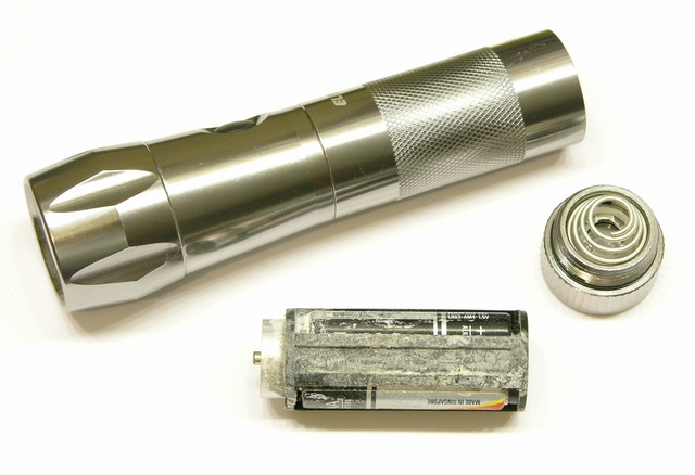
LED flashlight damaged by leaking batteries

I was given this high-quality, hefty, well-balanced, well-performing LED flashlight several years ago with batteries already in it. I keep it in the glovebox; and recently when I needed it, it didn’t power on.

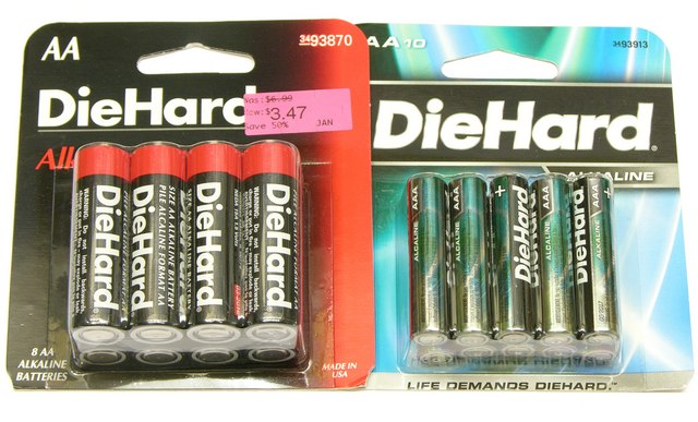
Packages of DieHard AA and AAA alkaline cells

In my decades of using consumer electronics, there’s only one brand of alkaline cells that has never leaked in my equipment — even things I’ve forgotten about and found again years later — and I drive miles out of my way to buy them.

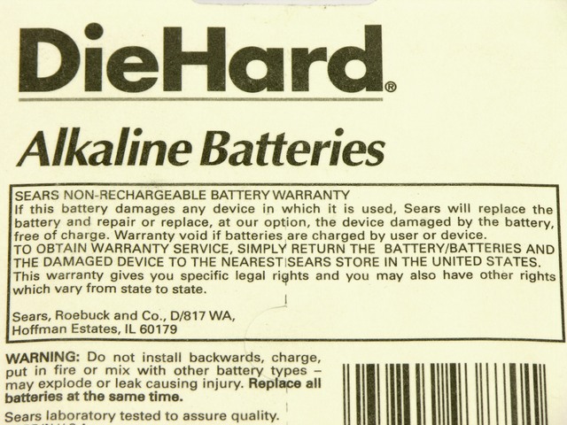
DieHard alkaline cell warranty

Doubtless someone will pop up with their own horror story, but I’ll still make the claim: You will never, ever, need this.

Cleaning the Flashlight

In order to get out the crud, I disassembled the flashlight completely and cleaned it with a wire brush, a wire wheel on the Dremel, a wire brush on the Dremel, and a toothbrush and dishwashing detergent. I went a little overboard to make sure I had got it all, but at every stage I was getting out more crud.

I’ve long been impressed with the heft and solidity of the flashlight; now that I’ve seen the inside, I’m equally impressed with its design and with the ease of (dis)assembly.

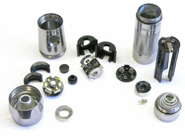
Element LED flashlight, disassembled

Loosely clockwise from the left, the reflector isn’t adjustable for beam focus but screws off anyway. The heatsinked LED has a separate plastic housing with beveled forward edge that centers the LED against the back side of its reflector cone. The LED housing’s retaining ring doubles as one of the LED terminals.

The aluminum head holds the LED housing and the separate LED driver housing, dropped in from the tail end, and screws tightly to the reflector. The plastic housing for the tiny power switch and LED driver board is made of two identical, completely reversible parts, holding in the inner power switch pushbutton on the one side and leaving a window to check board orientation for assembly on the other.

The rubber outer power switch pushbutton installs after the LED driver is dropped into the head and does not seal against the housing, suggesting that the o-rings on the aluminum housing are for a great feel during assembly and battery replacement rather than for water resistance.

The battery cage holds three AAA cells and assembles easily. The stiles are marked with the cell orientation; the filled cage looks a bit like a C cell and drops into the flashlight handle, with the spring-loaded button and the metal ring contacting corresponding surfaces on the bottom of the LED board.

The tail cap doesn’t make electrical contact with the battery’s negative terminal and the flashlight body doesn’t conduct current, as it does on many less expensive flashlights (not that I think I care).

Cleaned, reassembled, and with AAA cells reinstalled, it once again works perfectly. I look forward to many more years of service … and to not having to clean it out again.

Rebuilding the CupCake Extruder Heater (When It Wasn’t Very Broken)

Sunday, January 29th, 2012

After some success back in June using fans to cool extruded layers on my CupCake — in fact, right after that success — it slowed extruding and eventually stopped extruding altogether. This is the story of my life with the CupCake — a very brief success from time to time, but never persistent nor replicable.

When I say stopped extruding, I mean the motor actually ground to a halt. Usually it chews a divot into the filament, but this time it stopped. And I was pretty sure — don’t remember whether I actually checked the on-screen display or not — that the nozzle temperature had dropped and the filament wasn’t melting any more.

I know people talk about extruding ABS at temperatures as low as 200°C, and I don’t find that to be the case in my CupCake. Mine is calibrated, and mine doesn’t like temperatures that it thinks are lower than 220°C, and mine doesn’t really like temperatures that it thinks are below 225°C. So it really doesn’t take much to make it unhappy.
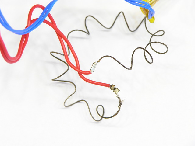
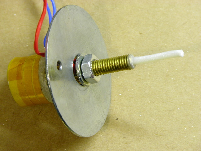
Nichrome wire crimped to teflon-coated wire

I had just rebuilt and rewound my heater at the time, and I knew that I had crimped the nichrome to the teflon-coated lead wires with silver crimp beads. I had a suspicion that the joints had become oxidized under the crimps, and the 7.3Ω resistance across my heater wires seemed high for my CupCake.

A couple of weeks ago I disassembled the heater and found that one of the two connections was indeed quite scorched and oxidized.
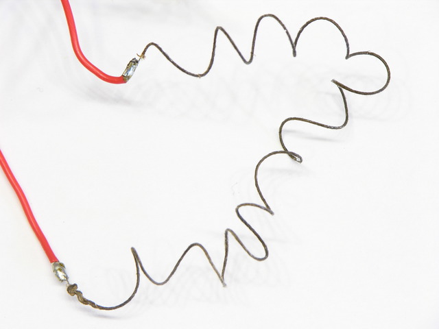
Nichrome wire crimped to teflon-coated wire

After cutting away the crimp tubes, cleaning the end of the nichrome wire with fine sandpaper, cutting back the lead wire, and recrimping, I tinned both lead wires with solder. Solder doesn’t stick to nichrome; but being coated with solder, the joint (which already had a solid mechanical connection from crimping) should be much less prone to oxidation.

After the rebuild, the heater measured 6.8Ω. Half an ohm difference doesn’t sound like that much until you’re trying to get to 225°C. Since power P = V2 / R, at 7.3Ω, P = (12V)2 / 7.3Ω ≈ 19.7W; and at 6.8Ω, P = (12V)2 / 6.8Ω ≈ 21.2W; so maybe that could be enough to make the difference at the high end of the extruder’s temperature range.
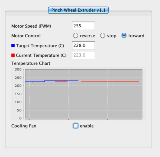
ReplicatorG control panel with temperature failing to reach set point

Aaaand … after reconnecting things, I still couldn’t get the temperature above 222-223°C, even though it now had some 7% more power. That doesn’t seem quite right.
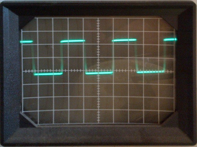
Pulse-width-modulated heater signal on oscilloscope

When in doubt, scope it out. Yeah, after almost a full minute of failing to hold the temperature at the set point, the software PWM in the extruder controller was still running the heater at about a 50% duty cycle. That definitely doesn’t seem quite right.

And isn’t something I can easily fix, either. The ReplicatorG version I was running didn’t have a control panel for the heater PID settings, so (even assuming I was smart enough to fiddle them into shape) I would have had to recompile the code each time I wanted to make a tweak, which wasn’t palatable.

Firmware Upgrade

But I thought I’d heard that newer ReplicatorG versions did bring the PID coefficients into the machine control panel, so I upgraded ReplicatorG from 0024 to 0029r2, and let it upgrade my firmware from v2.4 (I think) to v3.0, and lo! lost communication between ReplicatorG and the CupCake. It said it had a connection but all the menu options to talk to the CupCake were greyed out.

Great.

This is apparently a known problem claimed to have something to do with the Mac’s localization settings for the string representation of “,” and “.” in numbers. Srsly? And the suggested tweaks didn’t fix it for me, so I’ll just wait for the next ReplicatorG release. And since the Mac package of ReplicatorG continues to be a DMG file of all the pieces you have to drag into /Applications/ReplicatorG, rather than a ReplicatorG folder that one could conveniently drag into /Applications like everyone else provides … I guess I should feel lucky to have a Mac version at all, and I’m not holding my breath for a fix on this problem.

Anyway, downgrading ReplicatorG to 0026 restored my connectivity and got me a look at those sweet, sweet PID coefficients.
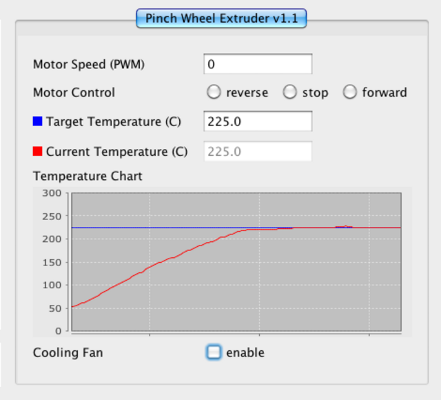
ReplicatorG heater temperature graph

Which I no longer need, ’cause with the upgraded CupCake firmware, the PID algorithm seems to work right. Reaching for the knobs was obviously an attempt at a workaround, and the real fix is oh so much better.
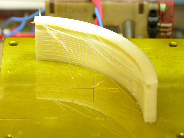
Plastic-extruded filter holder assembly

The stringing on this diffusing filter holder is my fault, not my machine’s — I have a 0° (or 90°) overhang on a concave curve, so there’s no way it was going to come out clean. I still wanted to see what it would do, and it performed admirably under the circumstances of an impossible model.

And then stopped working again.

Filament drive motor locked up against the filament. A-gain. (Yay, great grip on the drive pulley, and nozzle retaining washer not breaking!) Temperature claims to be steady where set.

My utility is fairly cold these days. I’ll try enclosing the build chamber again in hopes that although the nozzle is hot enough, the teflon tube is too cold — but I bet I end up disassembling and drilling out the inside of the tube and nozzle again.

Should have been designed with a quick-release.
Another CupCake Nozzle Jam, PTFE Thermal Barrier Swarf, Heater Winding, and Glass Transition

Sunday, June 12th, 2011

I had written about jamming my CupCake nozzle trying to extrude PLA and having to disassemble the whole nozzle to clean and rebuild it. I got new PTFE thermal barriers (the white Teflon® tube) from MakerBot, put things back together, and quickly jammed the heater with ABS, which I’d never done before.

MakerBot CupCake Plastruder MK3 heater barrel with ABS leaked around barrel/barrier junction

I conversed with Nop Head about the increased force required to push filament through the heater and he pointed me to the junction between the brass heater barrel and PTFE thermal barrier. It needs to be absolutely closed, and when reassembling I’d left a tiny gap into which the ABS expanded (covering the end of the brass in the photo), interfering with smooth flow of more ABS into the brass. He gave me this video link to a vivid demonstration of the phenomenon, in which he is attempting to push filament into a heater assembly that’s wide open at both ends:

He gave me the tip to reassemble the brass heater and PTFE barrier with a drill bit of the nominal hole diameter inserted. When the two are turned together as tightly as they should be, the PTFE will begin to deform and just barely begin to grip the drill bit.

Believing the filament hole through the PTFE is metric and not owning metric drill bits, I figured the next best thing would be to use filament itself (which would be slightly undersized; but I could tighten until friction increased and then back off slightly). To my surprise, I couldn’t push filament through just the PTFE tube by itself.

Upon inspection, I discovered swarf where the little filament hole from the top meets the larger heater hole from the bottom, and this swarf was interfering so much with the motion of the filament that even after forcing the filament end past it, I still had difficulty moving the ABS filament through the tube. No wonder the heater was jamming!

I reached into the large end of the hole with a rat-tail file and used its tip to push the swarf into the small hole, then filed it free by push-filing upwards into the hole. After cleaning the PTFE thoroughly, I reassembled the heater and fired it up again.

In the past, I’ve been able to hear my stock DC gearmotor slog down when the filament reaches a certain point inside the heater, and I’ve always assumed that was due to the constriction of the nozzle. Not so, as my motor no longer slogs, and instead merrily pushes filament through like chocolate sauce dribbling out of the corner of a topping pouch! I have to assume that my original PTFE barrier had the same problem (to a lesser extent) all along, and I wonder how many others out there do too.

Thermal Gradient and Glass Transition Phase

While rebuilding the heater, I initially thought that part of my original problem must have been the top of the brass getting hot enough to melt the plastic filament that close to the PTFE, as I had always pictured the filament melting somewhere inside the brass. I’ve also read about hot-end designs with a heater near the tip and a heatsink higher up to keep the feed area cool and the plastic solid while inside it.

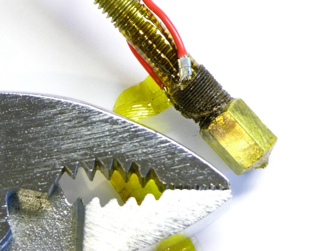
MakerBot CupCake Plastruder MK3 heater with nichrome wound near tip (doesn't work well)

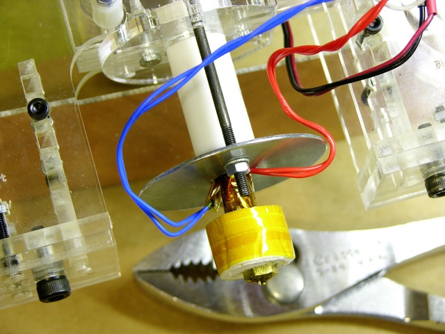
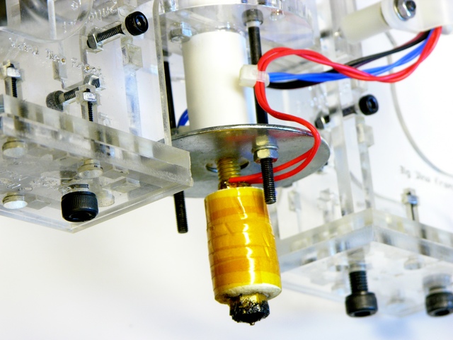
I thus rewound all of the nichrome near the nozzle end and thermally insulated only the tip, thinking the cooler area above would help keep the filament from melting within the PTFE.

MakerBot CupCake Plastruder MK3 heater insulated only at tip

Even though after deswarfing the PTFE, the extruder initially worked far better than it had before, it proved not to be as reliable as desired, and I did notice the filament feed beginning to bog down. I had an ongoing email conversation with Nop Head, and he gave me this fantastic explanation of the hot end, which I reprint here with his blessing:

Most of the temperature is dropped across the PTFE and the point where the plastic melts (when stationary) will be about half way between the end of the barrel and the top of the insulator. This is where it is most viscous, so it is is good that it is inside something very slippery.

Brass is about 1000 times more thermally conductive that PTFE, but the barrel has a much smaller cross sectional area, so the thermal resistances are not as far apart as that, but still considerably different.

When the filament is moving the melt point will be much closer to the top of the brass due to the time it takes to melt because ABS is also a very poor conductor of heat and has a high specific heat capacity.

It’s a shame PTFE is not transparent, as it would be a lot more obvious when things were not working.

I think when at rest the filament melts in the PTFE. When moving I think it only gets above the glass transition, so when there is a gap it expands into it and jams.

Well, heck! If that’s the way it works, it sounds like I want the brass heated evenly (at least in this Plastruder MK3 design) to keep the filament as soft as possible at the brass-PTFE junction.

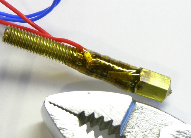
MakerBot CupCake Plastruder MK3 heater barrel with nichrome wound around entire length

I disassembled the heater yet again, this time rewinding the nichrome as evenly along the length of the barrel as possible and once again insulating the whole barrel. After reassembling, I haven’t noticed the feed motor bogging down as it was before.

PLA + Ignorance = Broken Extruder

Sunday, May 29th, 2011

I got a roll of PLA to try making some clear objects on the CupCake. I had read on the MakerBot wiki about the techniques for and challenges of printing PLA but still had trouble feeding PLA into the Plastruder MK3 and chasing out the ABS that I’d been using.

MakerBot CupCake Plastruder MK4 with stripped PTFE barrier

When feeding in the PLA, ABS came out for a while and then things stopped. Something happened inside the PTFE (Teflon) thermal barrier and the brass heater barrel was pushed out the bottom.

Later kits have a nut between the PTFE barrier and the metal washer so the long black bolts pulling on the washer in turn pull on the nut which has a stronger grip on the threads than the PTFE, dramatically reducing the risk of the brass barrel slipping out of the PTFE barrier and dramatically increasing the risk of cracking the acrylic retainer at the top. It’s recommended to replace it with a metal retainer.

PLA clogged on MakerBot CupCake Plastruder MK3 nozzle assembly

Today I had time to disassemble the Plastruder and unthread the heater barrel from the PTFE barrier. Looks like the PLA melted, the PTFE got warm and softened, the PLA oozed around the heater barrel, and then the PLA solidified and the barrel was pushed out the end of the softened PTFE.

I chipped the hardened PLA off the end, then searched for a solvent that would dissolve the PLA out of the barrel. I was surprised to find no information online (I do not assert that there isn’t any but merely that I didn’t find it) and tried acetone. During the time I waited, it didn’t dissolve the PLA completely, but it did soften it enough to scrape it out of the threads with a wire brush and goop it out of the barrel with a drill bit.

Scorched nichrome heater wire on MakerBot CupCake Plastruder MK3 nozzle

Since something in the thermal insulation had been previously damaged by deliberate immersion in water, I ended up deciding to peel apart the whole heater assembly. I suspect the water-soaked kapton tape adhesive closest to the nichrome heater is what scorched and I still have faith in the magical powers of kapton. I just know its weakness now.

On the bright side, I get to rebuild my heater from scratch and make it beautiful again.

On the dim side, I need to replace the PTFE barrier, which is swollen beyond even making contact with the brass threads, and the ceramic insulation that wrapped the heater, which was no longer pristine. I see that the MakerBot store has them in stock and affordable, and I reckon I’ll order them this week unless I hear a brilliant alternative first. The nichrome wire’s fiberglass insulation looks and feels intact — I think it’s saturated with scorch from the kapton rather than being damaged itself — but I’ll probably order more of it too.

Anyone successfully using PLA, I’d love to hear what temperature works well for you and what technique you use for changing from ABS to PLA.