Archive for the ‘Salvage’ Category

AMPduino [from 2011 Draft]

Friday, June 22nd, 2018

Another unpublished post dredged out of the distant past — this one apparently complete.

Soon after I got my friend Cort hooked on the Arduino, he said he wished he could easily carry it to the office to play with over lunch, to the tire shop to work on while he waited, etc. I offered him three-ring binders and boxed cases, but that wasn’t quite what he was looking for.

AMPduino case

After some discussion, we settled on an empty plastic case from a videocassette. I visited our Media Resources department, had their video director help me scrounge up a suitably large case (Cort says “U-Matic 3/4″ helical scan”), and updated the labeling.

AMPduino case, inside

Cort cut out the spindle posts and then stickied down the Arduino, a couple of breadboards, and some other things useful for prototyping and now does all of his development with the AMPduino. Handy for the workbench, the kitchen table, and the tire shop.

Replacing a Broken Power Jack on a DBX 266XL Compressor

Sunday, April 11th, 2010

I recently bought a DBX 266XL audio compressor/limiter on eBay. The seller described it thus:

Has light scratches, small amount of rack rash, in perfect working condition- no issues whatsoever. Has been used in my guitar rig for the past several years with no problems.

Broken C-14 power jack on DBX 266XL compressor

It arrived oddly but adequately packed and … as you can see, not in perfect condition. I would go so far as to say it had issues. I suspect had I tried to use it, I would have had problems.

Well … I could complain to the seller, who would tell me it was damaged in shipping, and then I could try to deal with the USPS who I don’t think broke it, and I could spend a lot of time and frustration and maybe get some money back and probably end up with no compressor. Or I could just fix it myself and have a little fun in the process.

(more…)

What Is This Thing?

Sunday, April 11th, 2010

I bought this at a surplus store a long time ago (twenty years?) thinking it was cool.

Front side of mystery plug strip

The front side has what I hoped would be lights but appear to be sockets. Positions 050 and 056 have broken off pins in them.

Back side of mystery plug strip

The back has wire-wrapped pins and Babcock PS-1224 devices, which I can’t identify. Fron context, I assume they’re some kind of matrix scanners.

I can’t decide whether it’s a patchboard (my best guess) or some kind of matrix input device — insert conductive pegs to connect rows to columns and indicate which of a thousand positions should … something.

Anyone?

Making Mini Extension Cords / Testing New Solder and Heatshrink Techniques

Sunday, March 7th, 2010

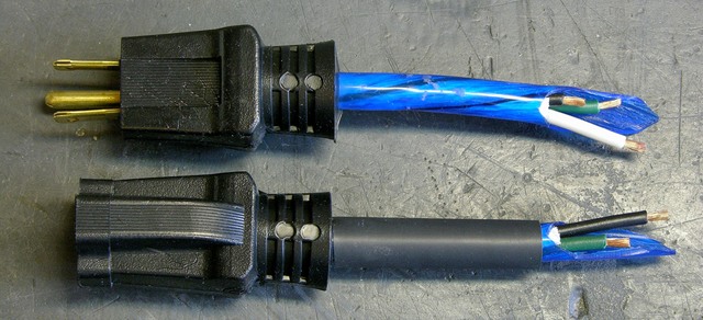
When you cut up an extension cord for speaker cable (I’m no golden-eared audiophile; I just need some copper to get a few hundred watts from place to place), save the ends to reassemble into mini extension cords. They’re perfect for plugging wall warts into receps and power strips without making adjacent receps unusable too.

I’ve spliced a lot of different kinds of cables — sometimes repairs for friends, sometimes Frankensteining things together for a project — and I’ve always been dissatisfied with the aesthetics when I’m done. Covering the joint in heatshrink hides the ugly splices from direct view, but the heatshrink tapers where it falls off the edge of the cable’s jackets and has unsightly bumps covering the solder joints.

This weekend I tried out a couple of ideas for achieving a smoother splice. The basic method was sound; and although the results aren’t yet what I hope to accomplish, I think they’re leading in the right direction.

Extension cord with jacket ends cut for splicing

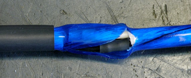
My first idea was based on a woodworking scarf joint — a fancy term for cutting ends on a diagonal to make a joint less visible. I sliced each jacket lengthwise about an inch and a half from the cut end, then attempted to cut the peeled jackets into smooth diagonals.

Offset solder joints in a cable splice

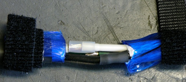
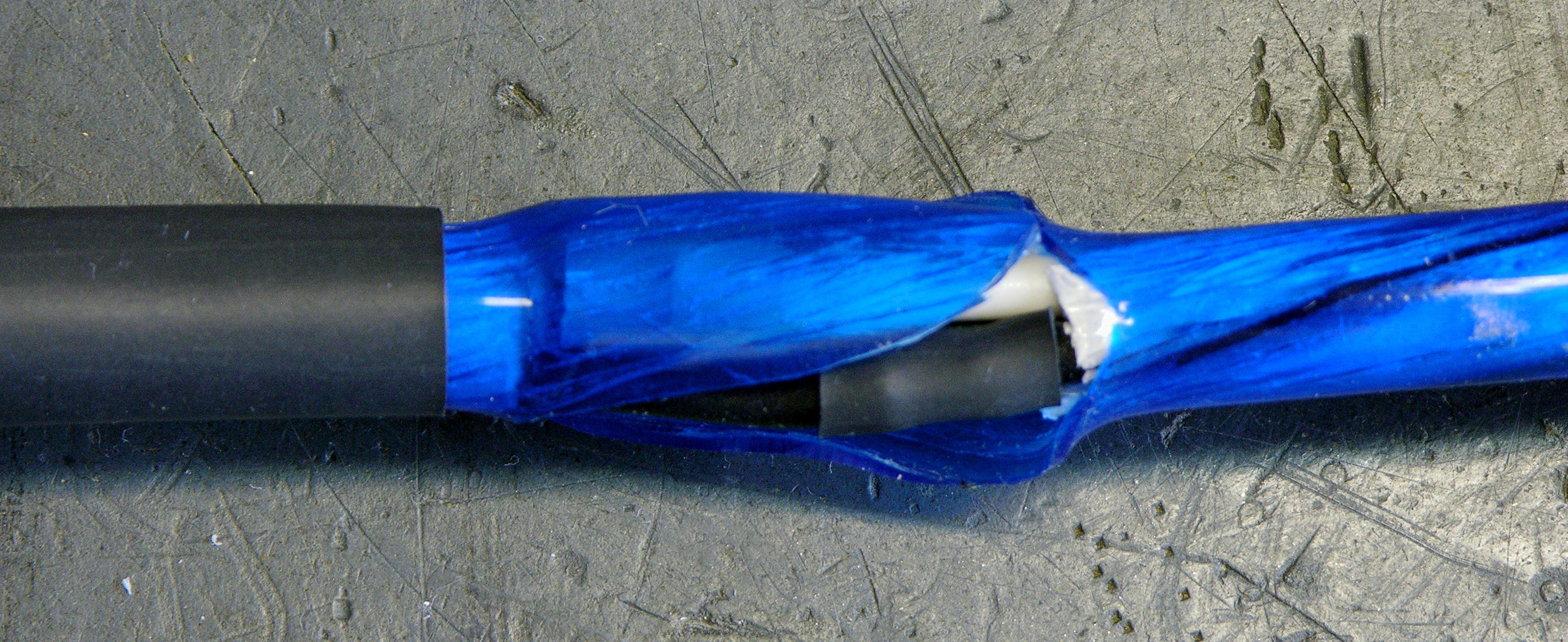
I tied the jacket pieces out of the way with velcro, preloaded the wires with heatshrink to cover the splices, and soldered the individual wires together. Note that the individual joints are all offset so that even if the heatshrink were to fail or be abraded, the exposed joints still couldn’t come into contact and short out.

Cable splice with jacket pieces not quite fitting

It turns out that eyeballing the mating jacket shapes before putting the cable back together is a bad idea (or at least that I’m not very good at it). I left a fair bit of gap, uh, everywhere — if I were to try it again, I’d wait to cut the scarf (scarves?) until the reassembly stage, at which point I could do a better job of mating them.

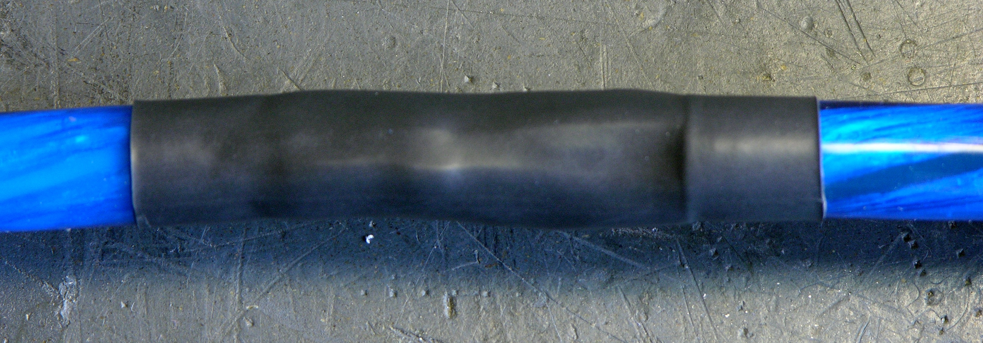
Note that the way the jackets flare out where they come from the unaltered cables into the joint is due to heat while heatshrinking the individual wires, not due to the bulk of the splice area.

Spliced cable with lumpy heatshrink

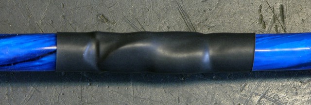
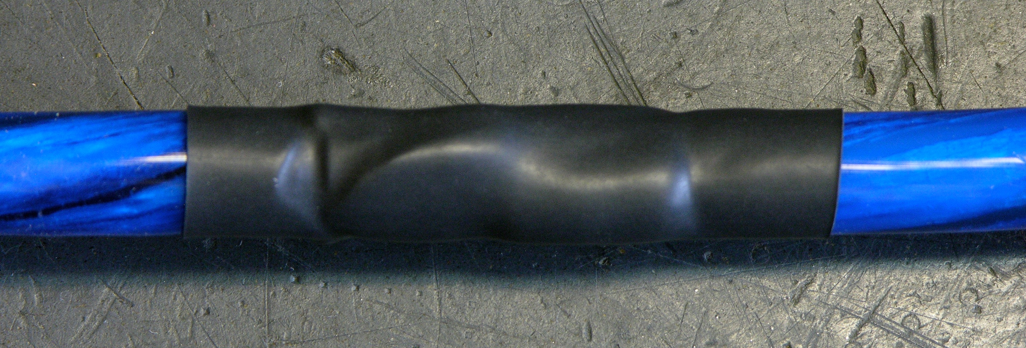
The result is arguably smoother than my previous methods; but because the lumps don’t logically derive from the splices inside, I actually find it more aesthetically displeasing.

Spliced cable with jacket rewrapped over joint

On the second cord I spliced, I slit the left jacket but didn’t shape the split end and I cut the right jacket completely off the cable. After soldering and heatshrinking the wires, I wrapped the left jacket back around the joint, covering it pretty cleanly. The gap where the two ends’ jackets meet is quite evident, but this shows that rewrapping the wires in the cables’ own jacket is a considerable improvement over just heatshrinking the joint.

Two spliced extension cords

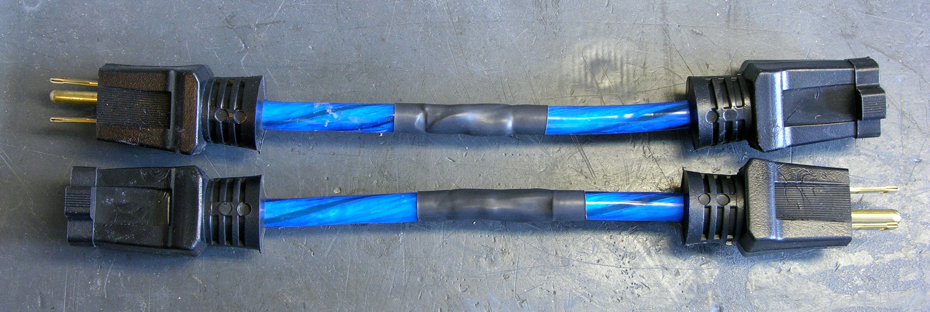
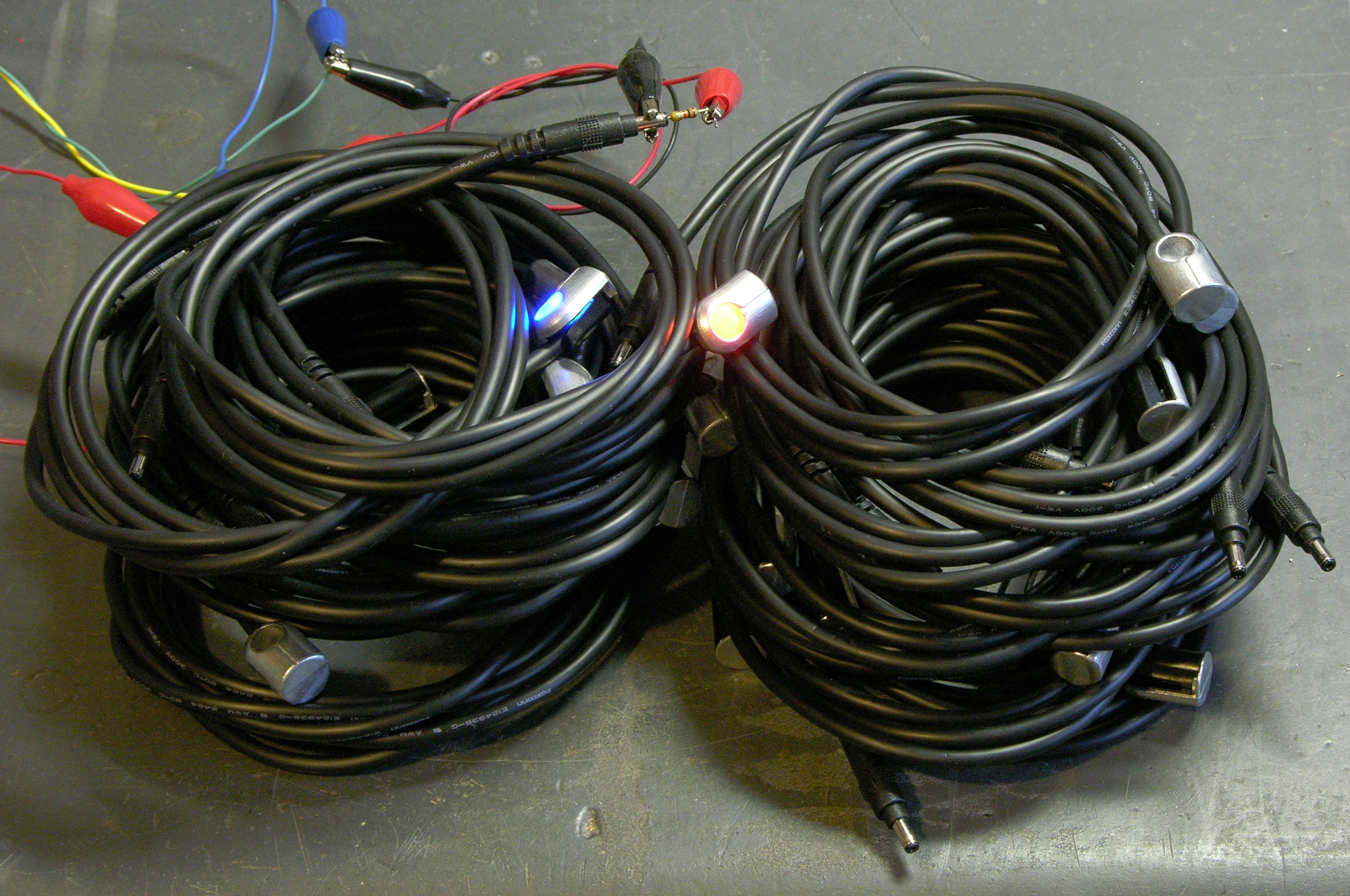
Two short cords, ready to use with wall warts.

For next time, I’m most interested in retrying the scarf joint and cutting the two jackets to mate after finishing splice. I think it offers a good chance of minimizing the gap at the end of each jacket, and I think the long diagonal gap under the heatshrink could be nearly invisible with a little care.

Obligatory cautions: Electricity is dangerous. Splicing cords is a bad idea. Don’t burn your house down. Make sure extension cords are unplugged before soldering. Do not taunt mini extension cords.

Need a Name for a New Site Feature

Sunday, January 31st, 2010

I have a lot of old electronics equipment that I thought I wanted to save at the time I got it but is of no particular use to me. I’d love to find new homes for it; some I’d give away for the cost of shipping and some I’d take offers.

I’m thinking about setting up a new area on my web server to post pictures of and information about things I have available, and I’d like a good name for it so I can link it as http://something.neufeld.newton.ks.us/ and http://www.neufeld.newton.ks.us/something/, but I don’t know what that name should be.

I’d love to call it http://free.neufeld.newton.ks.us/, but it won’t all be quite free. I don’t want to call it “store” because I’m hoping to turn a couple of my projects into kits soon and I’d like to reserve that name for information about the kits.

The best I’ve come up with so far is “fleamarket,” and I’m not wild about that.

Suggestions welcome. Free junk for the “winner.” :-)

Mouse Cables for CupCake Endstops

Tuesday, September 1st, 2009

I finished assembling my CupCake a week and a half ago — more detail in a separate post. For now, information about my decision to use mouse cables to wire up the endstops.

The CupCake comes with CAT5E (ethernet, among other things) patch cords to use to connect everything together. The X stage doesn’t have room for 8P8C (RJ-45) connectors on the Y-axis endstops, so you have to butcher the cables and put one new end on each. Ethernet patch cords are pretty bulky and unsupple; and I figured since I had to terminate my own cables anyway, I might as well use something more to my liking. I don’t fault MakerBot for supplying patch cords — it’s a great choice for most makers, and weirdos like me can always roll their own.

I only needed three conductors and headphone cable is pretty supple; but the very fine stranded wires inside headphone cable can be a bit of a challenge to work with. Cords from dead mice seemed like a better fit, even though they have an extra conductor I didn’t need. So I grabbed some from the “Keith box” at the office and got to work.

Mouse Guts

Interior of optical mouse

For those who haven’t seen it before, here’s the inside of an optical mouse.

(more…)

Two Birds

Monday, April 27th, 2009

I want to replace the abraded power cord on my brother’s sump pump in exchange for his letting me borrow it. Cort needs four panel-mount BNC connectors for an amateur radio handheld direction finder project. Convergence.

VideoCipher II television descrambler, front

Don’t panic. If for some weird reason you need one of these, I have more where this came from.

VideoCipher II television descrambler, rear

It’s a little hard to see from these shots, but the case profile is a weird trapezoidal shape.

VideoCipher II television descrambler, interior

Physically large linear power supply; two main PCBs.

Lithium 1/2 AA cell

Lithium 1/2 AA cell from April of 1989. Rated for 3.6V and still holding 3.69V after twenty years.

VideoCipher II television descrambler, PCB sliding out

Not sure why they used two PCBs (don’t tell me they really needed the extra 20 square inches), but it’s cute the way this one slides out.

Four PCB- / panel-mount BNC connectors

Every one of these had its shield pins broken free of both solder joints. Looked like cold solder, but I assume it was just mechanical stress.

Four PCB- / panel-mount BNC connectors

Voila! Four connectors for Cort. And a power cord for my brother, that I’m out of time to swap onto his pump tonight. Tomorrow, then.

Vintage Computer Keyboard Assembly

Saturday, March 14th, 2009

Joel gave me this keyboard a few years ago on the condition that I intend to do something interesting with it. That was an easy deal to accept.

Vintage computer keyboard assembly

Yellowed keycaps and lots of meta keys I’ve never seen before. Programmable function keys with a strip of LEDs next to them — and “lock” indicator LEDs carved right into the main keyboard keycaps. Onboard decoder logic and a 40-character 5×12-pixel vacuum fluorescent display. Does it get any better than this???

With the “PAR IND” key on the keypad, I have to admit that this was most likely from a word processing or typesetting machine. But I’d much rather believe it was removed from a Firefly-class transport ship.

Circuit board from vintage computer keyboard assembly

I can’t figure out how this circuit board ties to the keyboard, but it’s purported to go along with it. The model number is in a similar style, the sticker includes the same “Baugr.” label, and the ICs were also (mostly) manufactured in 1981-1982, so it’s plausible.

So per our agreement, I do intend to do something interesting with this. In my book, reverse-engineering it and hooking it up as an operating keyboard (with onboard display) would be pretty interesting.

All I need is time . . .

Storage Storage for Samples Storage

Monday, February 9th, 2009

In the past, I’ve tried several techniques for organizing my small quantities of IC samples (and “purchased samples”). I have enough different ones and each needs so little space individually that I don’t really want to dedicate parts bins to them.

IC samples in different containers

I’ve tried putting them in pockets in a three-ring binder, leaving them in the open shipping carton, and leaving them lying around on my workbench in their packages.

None of these have worked particularly well for me.

Mainframe Backup Tapes

At work, we have a large collection of “3490″ mainframe backup tapes, and they’re kept in large racks without the plastic cases the tapes ship in. In the IT environment, large sets of disks and tapes are referred to as “storage;” so the empty plastic cases and the racks the tapes go in are “storage storage,” right?

We had a few empty tape cases left, which were of no use to us and which I took home. We’ve also retired our mainframe and pruned our backup collection, so we have a number of empty racks and rack cases sitting around. It looked like an opportunity to salvage discarded materials and improve my electronic parts storage.

Tape Packages for Electronics Parts

Stacked tape cases with ICs

Last night I put most of my samples into empty tape cases, and it worked quite well. At Wal-Mart I found some Avery labels that are compatible with #5366 (2/3″ x 3 7/16″, called “File Folder — White”), are ultra-opaque, are supported by the label feature in OpenOffice, and fit nicely onto the approximately 1″ x 4.25″ case spines.

Racks (Or Not)

The cases have ridged edges and stack very nicely, but I was hoping to get them into a rack for easy “random access” to individual boxes.

Data tape case doesn't fit into tape storage rack

Unfortunately <grunt>, the racks <grunt shove> weren’t made to hold the cases <curse shove>, just the tapes <growl>, and the cases don’t fit <sigh resignation>.

Boxed tape cases with ICs

I still have some of the boxes that the tapes originally shipped in, but this isn’t necessarily an improvement over just stacking the cases. They’re still sort of “latched” together in the boxes, and it’s almost more difficult to pry a case out of a full box than to balance a stack of cases whilst removing a lower one.

I’ll keep looking — hopefully there’s a rack out there that fits the cases, that someone doesn’t need any more, that I can save from the landfill, and that I get for free. :-)

“Trash” from Cluster Computing Install

Monday, January 26th, 2009

After installation of the most recent rack of cluster servers at work, the high-performance team left a box of “trash” sitting around. Mel from Operations thought I might be interested and brought it to me, and he guessed right.

The box had all the usual detritus from the installation of new computers — manuals that I put in recycling instead of the landfill, warranty cards, used twist ties . . . and this:

In bags

Lots of plastic baggies containing things looking vaguely interesting.

Opened and sorted, I have:

Coils of remote LED indicator cables

Closeup of remote LED indicators

23 LED remote indicator assemblies with bicolor orange/blue LEDs at one end of 4′ cables and barrel connectors at the other,

Rackmount cable management clips

Lots of plastic guides to clip into the corner of a cable management piece and hold a cable in position, complete with installation instructions!,

Rack brackets and screws and feet

A pair of rackmount ears that I can modify to fit my refurbished 1U rackmount APC UPS, a very nice set of rubber feet that I think will replace the missing originals on my secondhand Akai Headrush delay/looping pedal, and a bunch of M5 machine screws for rack rails I don’t have.

Not bad for free.