Archive for May, 2008

Arduino I2C Expansion I/O

Monday, May 26th, 2008

Arduino with I2C connection to TI PCA9535 and PCA9555 GPIO chips

Cort and I are good friends and both interested in electronics, but have had surprisingly little opportunity to work on electronics together. He’s an amateur radio operator and very much into RF design, and I’m more interested in physical computing.

So when he started describing his receiver voter project and suggesting that I might be able to help out on some of the digital interfacing, I jumped at the opportunity. A radio repeater receives transmissions at one frequency and rebroadcasts them at a nearby frequency, effectively boosting the signal (by repeating it) without increasing transmission power over the legal limit.

The voter picks the best signal from several different receivers (possibly several miles apart, linked back to the repeater base) and routes it to the repeater. And Cort’s voter will have lots of pushbuttons, LEDs, and digital controls — more than he could wire directly to the Arduino he’s planning to use to control it.

That’s where I come in. Cort is very interested in learning the Arduino, but he hasn’t done much with microcontrollers lately and is to some extent playing catch-up with a decade’s worth of advances in technology. So I’ll pitch in and give him some ideas and programming assistance on the digital I/O.

I2C I/O Expansion

I started by looking for digital I/O expansion chips, and I did not start by looking for I2C. I’ve never worked with I2C before and I thought I’d find something with SPI, but oh no, that was not to be the case. Nearly everything I could find — and everything I could find that was readily available and affordable — used I2C. This is actually a good thing — I2C uses only two interface pins to talk to up to 127 devices, and SPI needs two pins for the bus plus a separate chip select line for each device — but it wasn’t what I was hoping for when I started looking.

So I ordered some samples, warmed up by trying to interface to an I2C EEPROM I had lying around (with no luck whatsoever, although I now know several things I did wrong and will go back to it soon), built some breakout boards, and got I2C communications up and running on the Arduino this weekend.

And the number of mistakes I made along the way was staggering. Not just little misunderstandings, but mind-numbing stupid mistake after stupid mistake, things I’ve know better since I was six. With a weekend like this, it’s a wonder I haven’t run over myself with my own car somehow.

So do what I say, not what I did.

Arduino I2C

First off, I had to get the Arduino talking to I2C. There’s not much online about doing I2C on the Arduino, and the most useful for me was Julian Bleecker’s blog post prosaically entitled Arduino and the Two-Wire Interface (TWI/I2C) Including A Short Didactic Parenthetical On Making TWI Work On An Arduino Mini.

It turns out there’s a Wiring library called Wire (why not, oh, say, I2C???) that operates the ATmega’s hardware I2C port and which has been incorporated into the Arduino software since version 6, so everything I needed was right there; I just had to figure out how to hook it together.

Between the Wire documentation being sketchy and not explaining how each function corresponds to an I2C function, its code examples being outdated and occasionally incorrect, my lack of familiarity with I2C in general, my not yet having a working I2C circuit to reference, and of course my many, many mistakes, this made for a bit of a vexing experience.

Let’s do it.

(more…)

SOIC Breakout Boards

Monday, May 26th, 2008

I’m getting ready to collaborate with Cort on a project using ICs that aren’t available as DIPs; so I got some SOIC samples, and this weekend I hacked up some carrier boards to break them out to .6″-spacing DIP.

Completed SOIC-24 breakout boards

I made a few extras — as many as I could fit in my little etching tray — so I’ll be set for a while.

I also want to give the design away to anyone who wants it. It’s nothing special, but it might save someone else some time. So I’ve created a Free Circuits page where I’ll post things for free download under a Creative Commons License Creative Commons Attribution-Share Alike 3.0 Unported License. All the code I post here I do with the intent that it may be useful to someone else; but it’s nice to be explicit about it once in a while.

On to the Board . . .

I laid out the board, then panelized it as large as I could fit within free EAGLE, which turned out to be four wide by two high.

Circuit board layout of SOIC-24 breakout board, panelized 4x2

Here I’ve corrected it to put space between adjacent boards; but I didn’t think of that until after I’d etched mine, which made for some tricky separating.

SOIC-24 breakout boards, etched

I did my usual toner transfer with the household iron, then used a Staedtler super-fine pen to touch up some spotty areas along the edges. The boards came out really well, in spite of using fairly tight spacing (12-mil traces with 9-mil separation by the middle pins). I inspected all the traces with a photographer’s loupe to be sure they had continuity where they should and separation where they shouldn’t.

PCB scored in vise

Having stupidly left the individual boards touching each other on the layout, I wasn’t quite sure how I was going to get them apart cleanly. But I tried a new method, clamping them in my bench vise and using the jaw’s smooth edge as a guide to score front and back with the corner of my best $3 chisel. You can just barely see the score line above.

PCB scored and snapped cleanly in vise

The boards snapped off clean as could be! I’ll definitely be using this method more in the future, even on boards I haven’t screwed up.

Desoldering with a Heat Gun DOESN’T Ruin Electrolytics

Sunday, May 18th, 2008

After repairing the Alesis monitor speakers by replacing overheated electrolytic capacitors, and then having one break again within a couple of minutes the first time I used it, I started to get a little paranoid about electrolytics and heat. In particular, I wondered, am I baking the electrolyte and ruining the capacitors when I bulk-desolder with my heat gun?

Gave it a little test today. The power supply board from the dead Optoma projector had a bunch of nice electrolytics on it, so I tested their ESR with my Capacitor Wizard, desoldered the board with the heat gun, and tested the caps again.

No perceptible increase in ESR, and I’m really glad to know that I haven’t been (directly) ruining capacitors all along. Yes, the extra heat probably speeds them on their way; but at least it’s not immediately fatal.

Repairing an InFocus LP290 Projector, Part 2

Thursday, May 8th, 2008

Last fall I bought a used InFocus LP290 projector, and in January I opened it up and found that the polarizing filter for the blue LCD was melted. Since then I’ve been keeping an eye out for a replacement filter, and Monday night I parted out a dead Optoma projector from Jeremy for the polarizers. Tonight I fitted one to the InFocus, with surprising success.

LCDs and Polarizing Filters

A long time ago, I think I knew how LCDs work, but I’d forgotten until a great conversation I had with Dave, who posts comments here from time to time and is immensely knowledgeable about LCDs. To paraphrase:

In high school physics, we learn that light behaves as both particles and waves (both of which can be demonstrated experimentally). In the wave model, light is a transverse wave: it “wiggles” from side to side in a plane containing its line of travel. (In contrast, sound is a longitudinal wave — it makes compressions and rarefactions back and forth only within the line of travel.)

Normal light has waves wiggling in all directions around the line of travel — up and down, side to side, and all angles in between. A polarizing filter only lets through light waves wiggling in one particular orientation, say up and down. It also lets through the up-and-down component of waves wiggling at an angle other than up and down; but waves wiggle side to side have zero up-and-down component and get completely block.

Digression: polarizing filters are used in photography and in sunglasses to block glare. It turns out that the light waves in certain kinds of glare have been polarized by their reflection off the surface of whatever object is glaring, and polarizing filters can completely block those types of glare. It’s a really cool effect to rotate a polarizing filter in front of something that’s backlit at a fairly steep angle and watch the glare appear and disappear.


I have this description backwards. See Dave’s comment for an excellent description of how it really works.

Back to LCDs: the crystals in LCDs pass light waves untouched when they’re inactive, and twist the polar orientation of light waves when active. This is the key to how LCDs work.

An LCD screen like on a cheap calculator has a polarizing filter in front, the LCD panel, and a backing mirror. Light from the room hits the filter and only the portion in the proper orientation (say up and down) passes through. That light then passes through the LCD, and where the LCD is inactive the light maintains the same orientation. It reflects off the back, passes through the LCD untouched again, and is already in the correct orientation to pass through the polarizing filter on the way out. Thus where the LCD is inactive, you see light areas.

Where the LCD is active, it twists the polarization of the light waves by 45°. (There are other possibilities, but I’m talking about simple and cheap.) It reflects off the mirrored back and passes through the LCD again, getting another 45° of twist for a total of 90° with respect to the polarizing filter. That’s exactly the angle of polarization that’s completely blocked; so where the LCD is active, you see dark areas.

In projectors, with light passing through the LCD only once, it has to work a little differently. I’m guessing the LCD does 90° of twist, with polarizing filters both before and after.


So without the “before” polarizing filter in the blue light path of my projector, the darkest the blue beam could ever be was about medium-bright, because it only got half as filtered as it was supposed to. Instead of true blacks, I got medium blues. White was still white, of course, because that’s where the light was supposed to pass through (and still did).

Colored Polarizing Filters

Looking at the optics inside projectors, there are lots of things reflecting, refracting, and filtering light, and I often see color tints and have trouble determining which thing I see is the color filter. So after taking the first polarizing filter off the Optoma and finding it to be a dark blue-grey, I thought it was a neutral grey and didn’t think any further about color.

Tonight I found that each polarizing filter is a different color, complemenrary to the color of the light path it’s installed in. I was having trouble figuring out why you’d want to have a color filter and a polarizer. Since the yellow-orange filter blocks blue light in the blue beam, it seemed it would simply dim the blue beam all around. Okay, that leads to blacker blacks; but (apparently) in the same way as just using a dimmer bulb. That didn’t make any sense.

Then I looked through the colored polarizing filter more carefully.

Desk viewed through orange polarizing filter from projector, sideways

Desk viewed through orange polarizing filter from projector, vertical

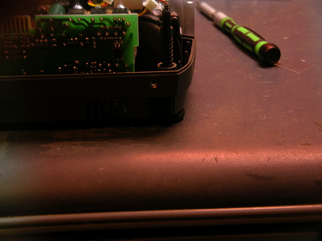
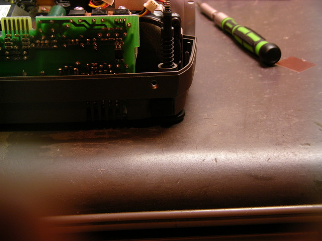
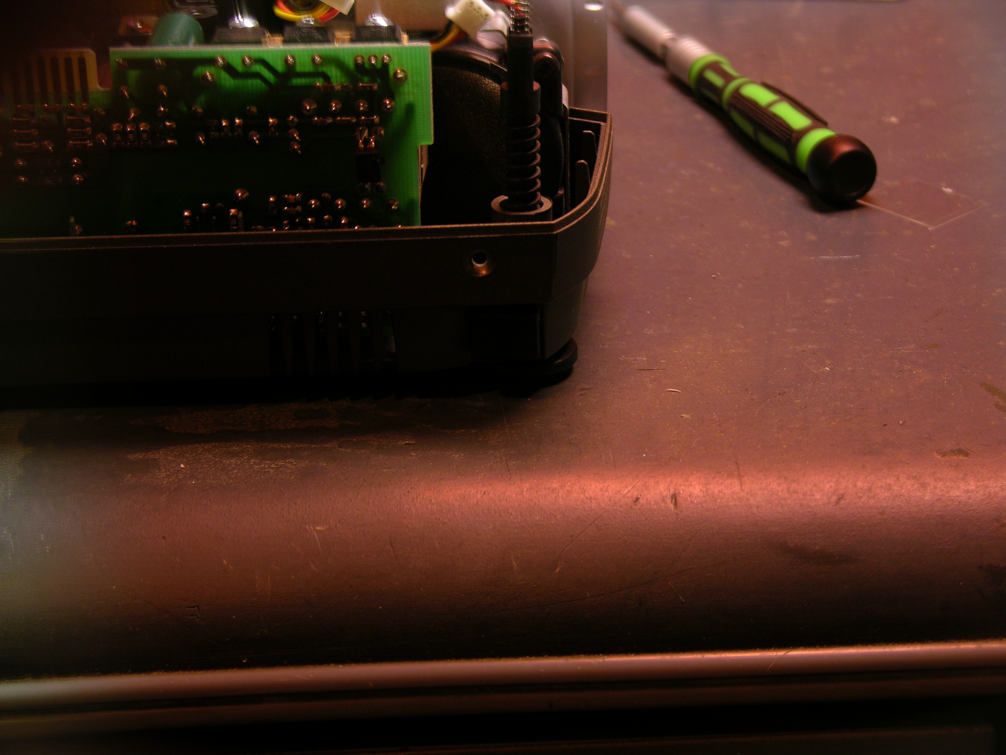
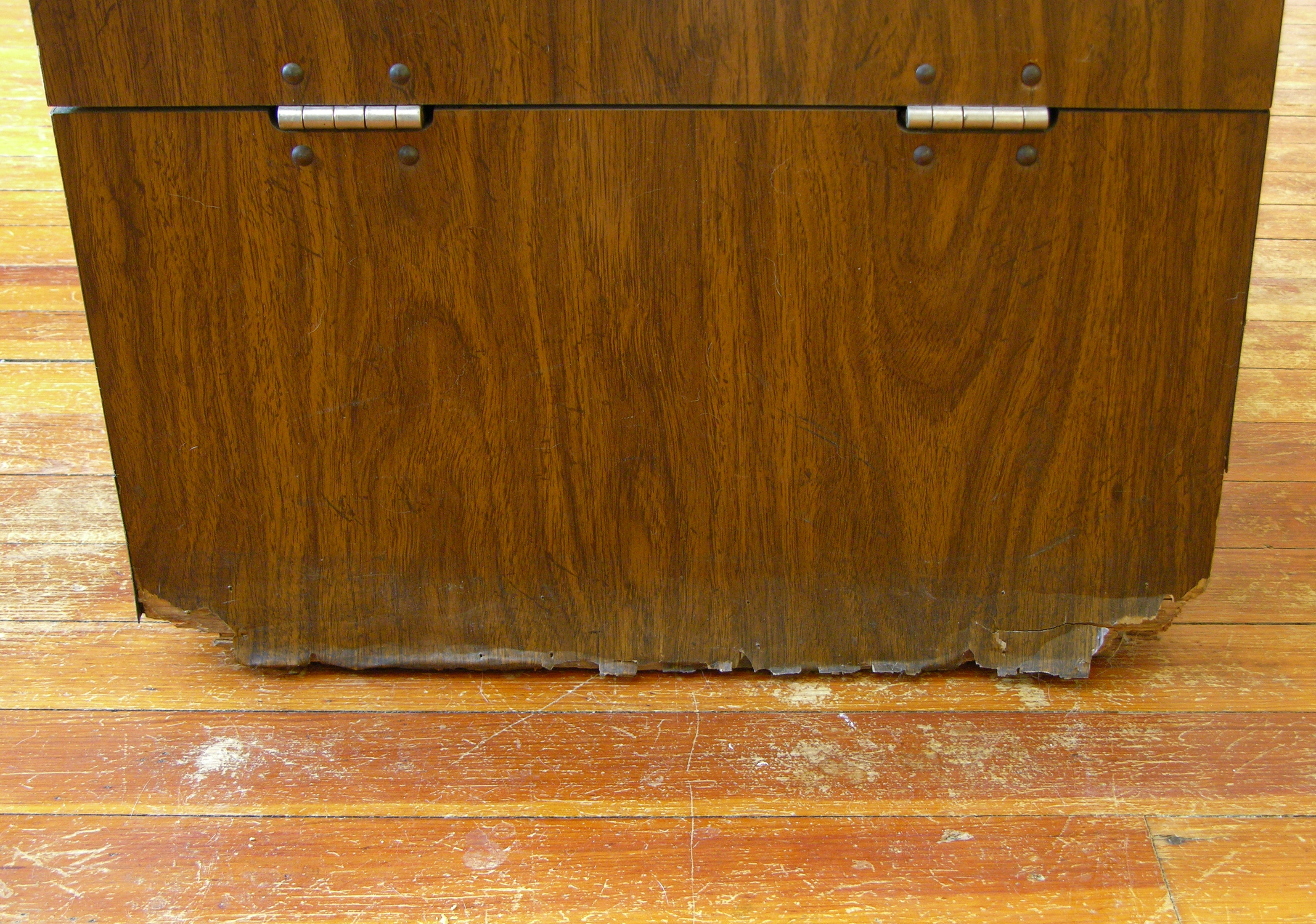
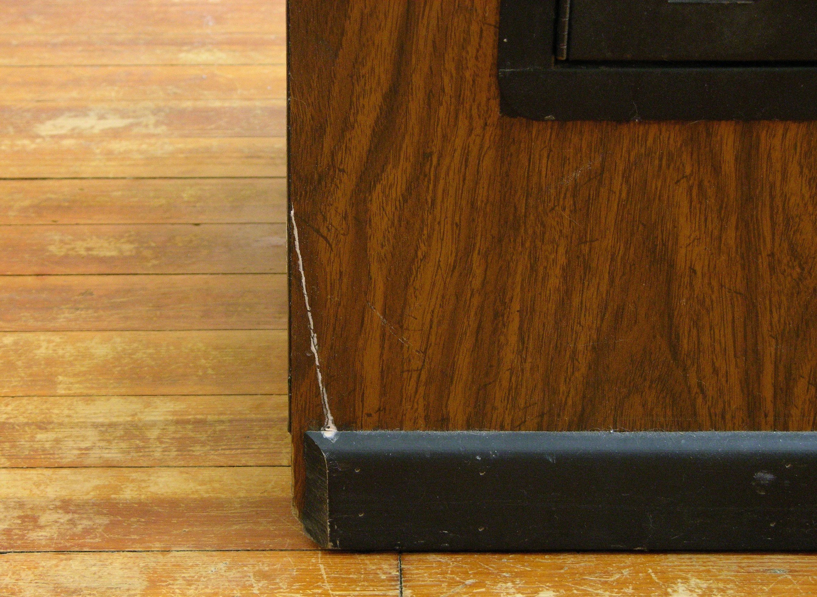
The two pictures are taken with the same camera settings, the first with the orangey filter held in front of the lens horizontally, the second vertically.

Both pictures have the orangey cast to them, but notice in particular the color of the glare on the edge of my desk. In the second picture, it’s nearly white, not orangey like everything else. That’s where the glare is.

I believe this filter passes all colors of light in general, and specifically blocks blue light that has opposing polarization. That’s why the screwdriver looks about the same in both pictures — everything except blue gets through, and the light from the screwdriver isn’t polarized so the blue is blocked. The glare on the edge of the desk is polarized, so even the blue gets through and gives a more even white.

That’s kinda cool. And that means the filter should do an extra good job of darkening blues where the LCD is active. With a complementary-colored filter in each of the three color beams, it means it should do a really good job of making black blacks.

Fitting the Filter to the Projector

The InFocus and Optoma obviously don’t use the same size filters, as the Optoma filter clearly doesn’t fit the InFocus carrier. Fortunately, the Optoma filter is larger, so at least I can hack it to work.

Projector polarizing filter fitted into different carrier

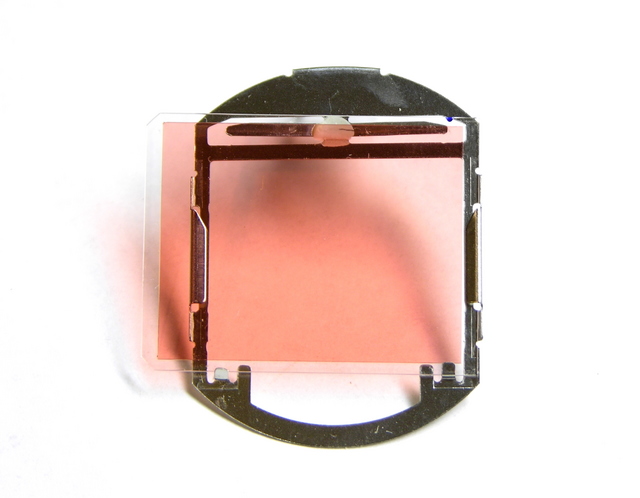
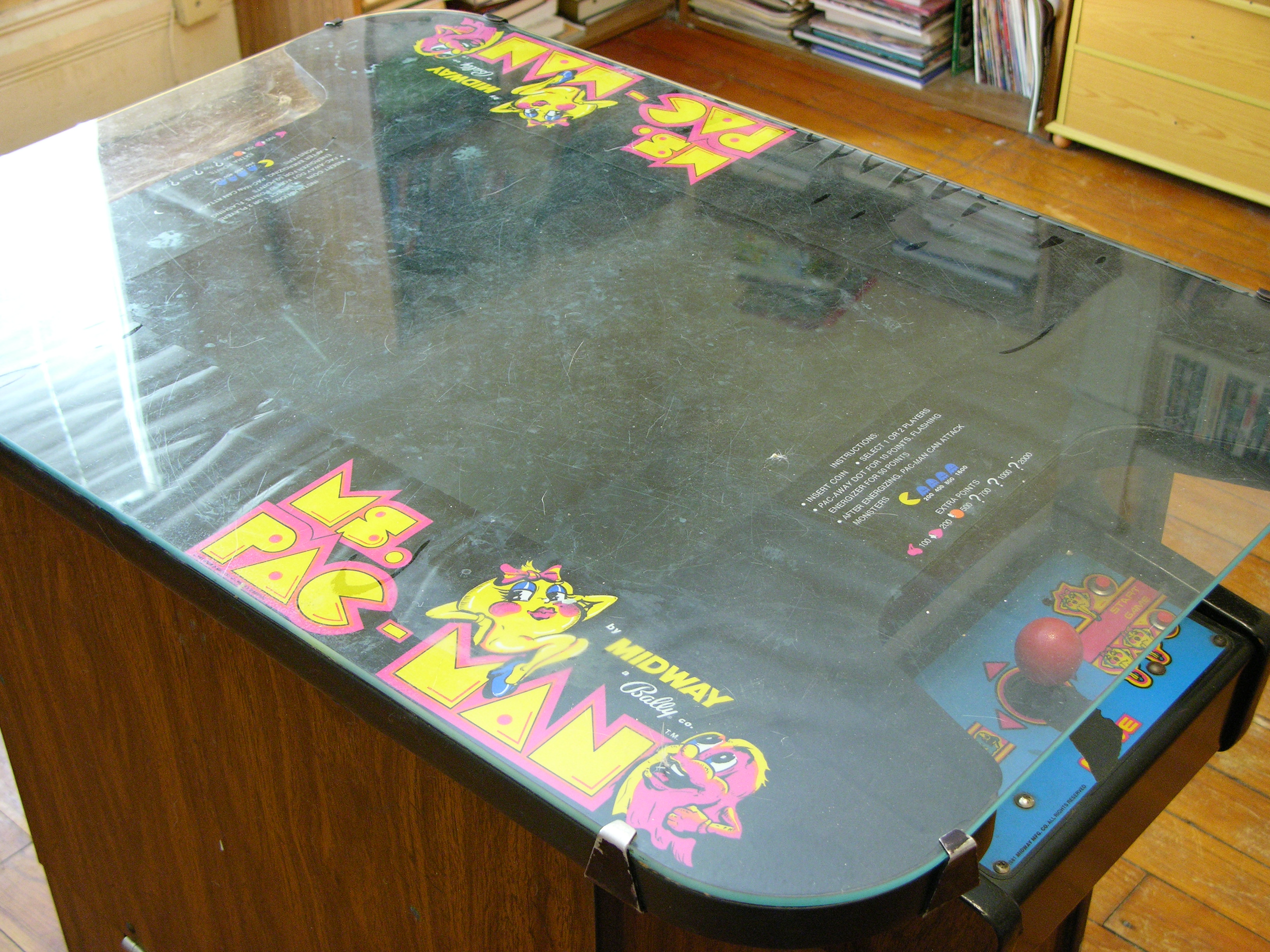
(The camera doesn’t represent the filter color very well, by the way. In real life, it looks very similar to the deep orangey-yellow of yellow liquid food coloring, not as pink as it looks here.)

I confirmed the proper orientation for the filter by very carefully slipping it into position in the projector and holding it there with a needlenose pliers with the projector running, and the proper orientation is horizontal. Too bad, since the Optoma filter was as tall (short dimension) as the InFocus carrier is wide (long dimension), and it actually fit really well in the carrier the wrong way.

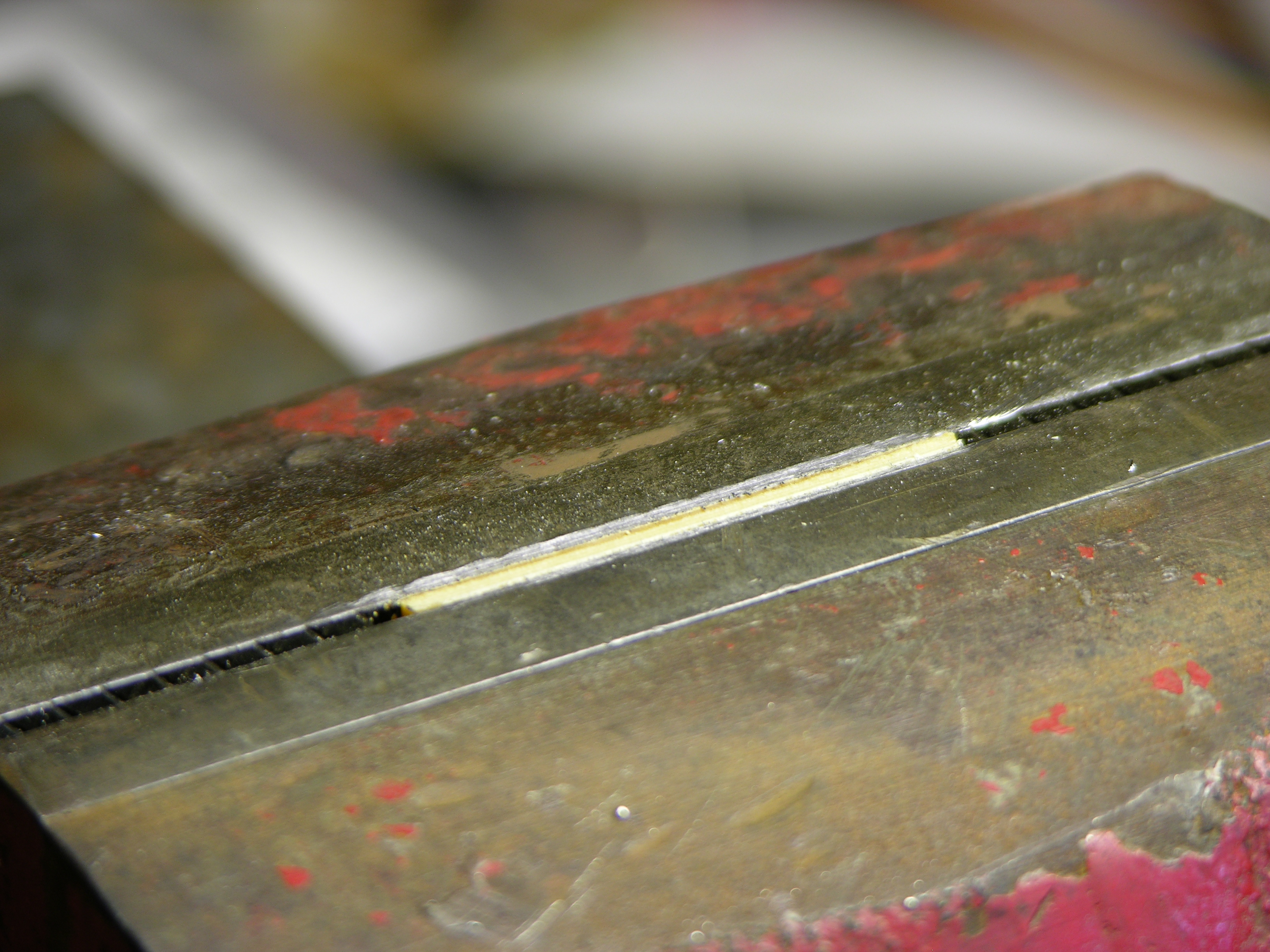
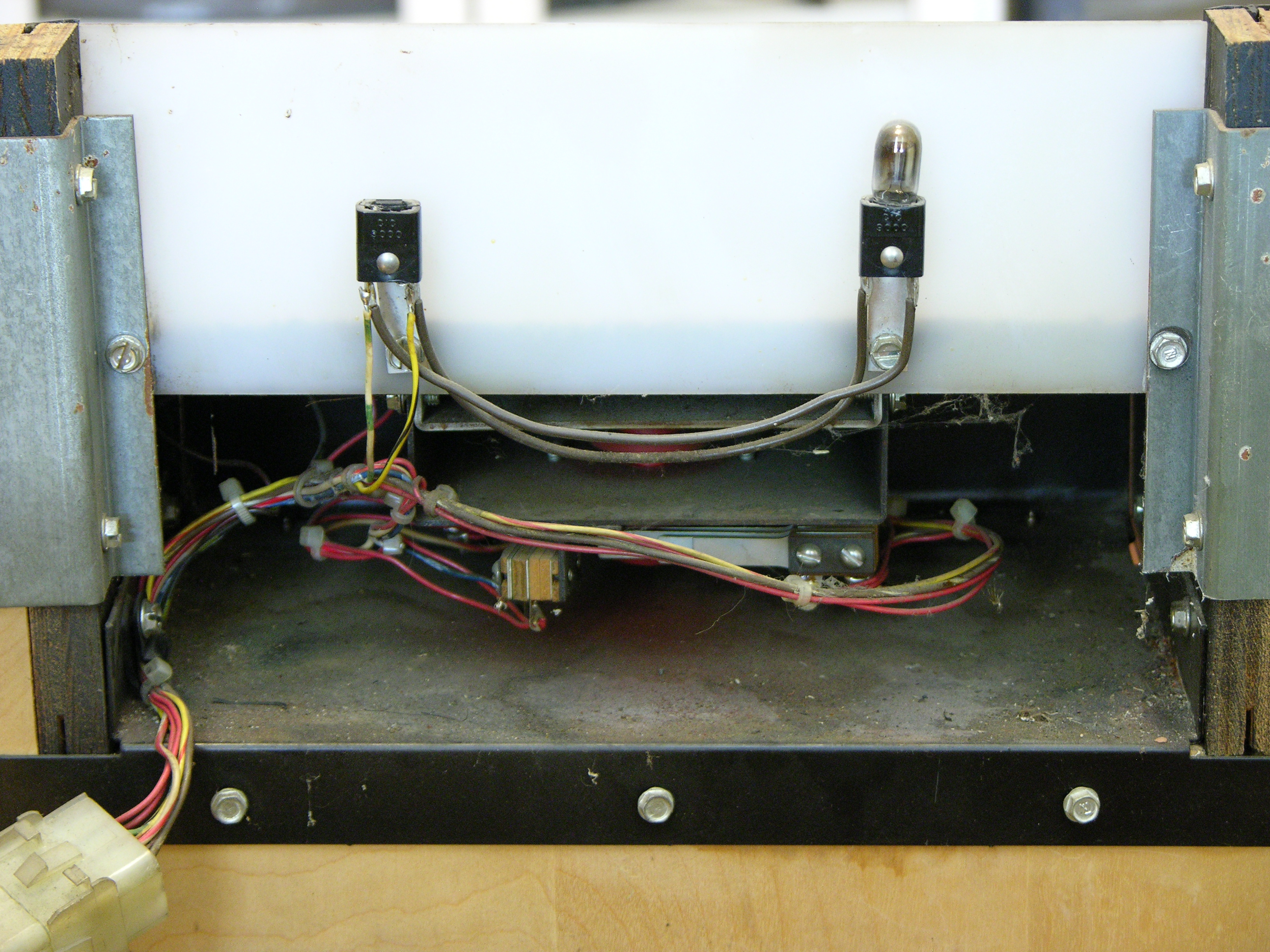
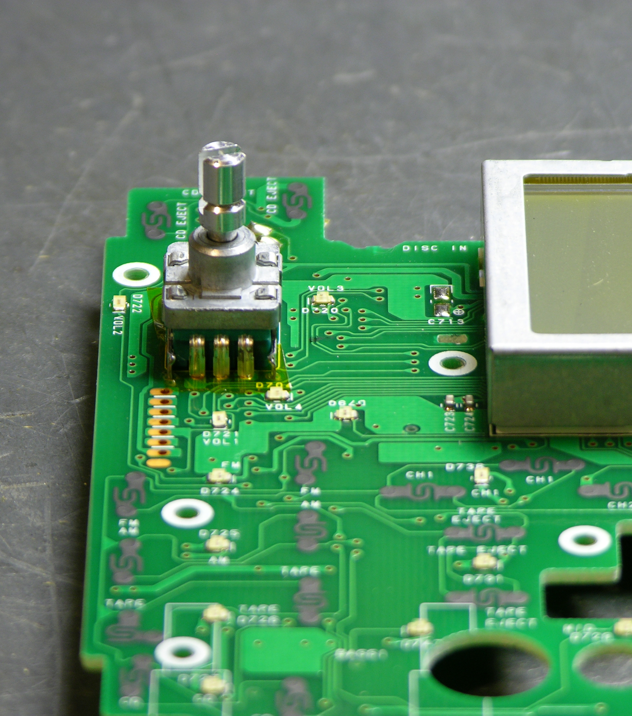
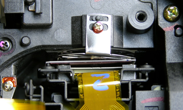
But with a little bending of the carrier edges, I got the too-large filter secured in (and hanging out of) the carrier well enough to reassemble the projector. The glass isn’t parallel to the carrier any more, but I can’t think of any reason that’ll make a difference. You can see the glass slide sticking too far to the left, and slanting forward, in this picture, between the silver carrier mounting tab above and the LCD housing below.

Hacked polarizing filter installed in projector

The projector works now, and the blacks are black again! I’m not ready to close it up and call it done until I sit next to the projector and test it for an evening to make sure it’s not going to melt down and light my house on fire, but I’m optimistic. And if it works, I’ll think about cutting down the glass the filter is mounted to, so it fits properly.

Meta: Enabled HTTP Compression

Wednesday, May 7th, 2008

I just enabled HTTP compression for all text content on my blog. (Images are hosted externally on a server I don’t directly control.) For anyone viewing my site directly, I’d be curious whether it seems to load faster, and of course if any problems are experienced.

Parting Out an Optoma EzPro 610H Projector

Monday, May 5th, 2008

I just disassembled a dead Optoma EzPro 610H projector from Jeremy, to look for a polarizing filter to fix my InFocus LP290 and see if Marsh Ray can fix a Sony VPL-PX15. The filters from the Optoma look to be about the right size for my InFocus, so I’m excited to think I may be able to get it working again 100%.

Meanwhile, I ended up with a whole bunch of parts I don’t need, some of which might be useful for repairing other EzPro projectors. I’d like to offer these to anyone who could use them, for whatever you think they’re worth plus the cost of shipping. If you’re interested in any of these, see below for instructions.


Update 06-May

Jeremy says:

Had power indicator lights, but bulb would not light. Replaced bulb, same deal.

So the problem is likely in one of the logic boards (microprocessor not responding to sensors that say it’s okay to power up the lamp) or power supply boards.


Available Parts

Projector lamp

Projector lamp. Sold. I don’t know whether it works, I don’t know how many hours of use it has, and I don’t have any way to test it. I believe lamp failure is not what killed the projector.

Projector lamp power supply

Lamp power supply. I don’t know whether it’s good and I don’t have any way to test it; but it’s modular enough, if you suspect it’s what’s wrong with your projector, it’s worth trying.

Interlock switch

Lamp service panel interlock switch. Not very exciting . . . but handy if, um, mice have been living inside your projector.

Three projector cooling fans

Three cooling fans that mounted to the optical housing: rear left, right, and bottom.

Two projector cooling fans

Two cooling fans that mounted to the case: bottom and front.

Projector input panel

Video input panel and associated PCBs.

Projector control panel

Top control panel and attached PCB.

Projector LCD panels

All three LCDs are available, removed from the prismatic lens thinger on the left and without polarizing filters. I removed the red LCD (right) from its mounting frame (further disassembled than it is here) before I found where the polarizing filter was (elsewhere), so it needs some RTV reapplied to hold it firmly in its frame. This will be obvious upon inspection.

Projector book, handle, and remote control

Owner’s manual. Sold. Carrying handle. Remote control that looks slightly different than what’s in the book but has the same part number. Sold.

NOT Available Parts

I’m NOT giving out the following, so don’t even ask:

  • Any of the optics. I think they’re unlikely to be damaged in anyone else’s projector, I think they’d be difficult to replace and realign successfully if they were damaged, and I think they’re kinda cool to hang onto.
  • The projector’s main board and main power supply board. I think they’re too likely to have been the source of the problem with this projector, and I’m just going to harvest them for components.
  • The last polarizing filter. I’m going to hang onto it for a rainy day.

How to Make a Request

If you’re interested in anything from here, post a comment below indicating what you want, what it’s worth to you, and what your ZIP code is. Make sure you enter your email address correctly on the comment form, because that’s how I’m going to contact you.

Then add my email address, neufeld at this domain, to your address book or whitelist. Because I have an unusual domain name and because I run my own email server, a lot of email from me ends up in people’s spam folders. I will only email you once. If you want something from me, make sure you receive that email.

I’ll contact you shortly to let you know whether I still have the item, and how much shipping will cost. You PayPal me the cost of shipping only, and I’ll send you the item. When you get it, if it works, you PayPal me whatever you think it’s worth. If it doesn’t work, you send it back at your expense and I’ll add it to my junk pile.

Bought a Ms Pac-Man

Sunday, May 4th, 2008

A month ago I added a Ms Pac-Man cocktail table to my arcade game collection. I don’t even like Pac-Man games; but I’ve always figured I should have one, and this was the right opportunity. The eBay seller was right here in my hometown, saving me considerable freight and/or transportation expenses, so the $400 final bid wasn’t too painful.

Seeing games in person that I’ve purchased on eBay is always an . . . experience. From the seller’s pictures, I would have rated this about a 4/5 on my personal scale — no cabinet or artwork damage, everything works, but maybe some grime on the control panel and some burn-in on the monitor.

After picking it up, it was obvious that it was more like a 3/5, again on my personal scale. It was nothing the seller was concealing deliberately — he’s obviously not a collector and just didn’t know any better. I’m not upset about it; it’s all reparable, I’m used to it, and I still feel I got a fair deal. It just means it’s going to take a little work.

Here are the things that immediately caught my attention.

Physical / Cosmetic

Water-damaged cabinet

The plywood at the bottom of the back side of the cabinet has considerable water damage.

Scratched cabinet

There’s a large scratch near the bottom of the front side of the cabinet. It looks fresh — I think the seller did it wheeling the game sideways out of his basement on a strapless (non-appliance) dolly, after I specifically told him on the phone that I wanted to carry the game out of the basement by hand with my brother.

One of the leveling feet is missing.

Dirty Ms Pac-Man tabletop glass

The tabletop glass is filthy, apparently on both sides, even before I got it home and the cats started sitting on it.

Worn tabletop glass clip

The clips holding down the tabletop glass are mismatched and the paint is worn off of many of them.

Wrinkled Ms Pac-Man table art

The tabletop overlay is seriously wrinkled. Around the edges where it overhangs the player controls (!), I can’t feel any adhesive on it at all. It looks to me like a cheap repro that just sets in place.

Ms Pac-Man cocktail control panel

The player 1 control panel overlay is torn out below the joystick. (That’s not a shadow.)

Missing control panel backlights

The lights behind the translucent panels that illuminate the player controls aren’t illuminating. One is missing and the other three are apparently all burned out.

Coin door with burned-out light

One of the coin door lights is burned out.

Power plug

The power cord and plug are obviously not original. Yeccch.

Electronics

Ms Pac-Man speed chip

The game has the “speed chip” that makes Ms Pac-Man move way too fast. I prefer my games to be in original condition with default configurations.

Ms Pac-Man screen

The monitor is dim and has the brightness turned up high enough to see the vertical retrace and to see the black background glowing.

The monitor has keystone and vertical linearity problems. (The bowing of the whole image toward the left is fisheye from my digital camera; the vertical shrinkage toward the right is the monitor.)

The monitor has blotchy color in the upper left and needs to be degaussed. (So is the built-in degaussing circuit not working???)

Repairs

All in all, it’s going to take a little bit of work to get this back to nice condition, much less truly tip-top (which is impossible with the water damage on a veneered cabinet).

I’ve started already by finding a ROM image for the original chip that the speed chip replaced, and some 2532 EPROMs to put it on. Turns out I had 2516s, 2732s, and all manner of other 27xx EPROMs, but no 2532s. And don’t ask me why, but I didn’t feel like erasing and overwriting the speed chip.

2500 and 2700 EPROMs aren’t pin-compatible and I really didn’t want to build a carrier board. Fortunately I packed up a batch of allegedly-new 2532s on eBay, got Joel to burn my new ROM for me . . . and lost where I put it already. Oy vey.

Rotary Encoder from a VW Car Stereo

Sunday, May 4th, 2008

or

A Well-Stocked Junk Bin is the Mother of Having Everything You Need


July 7, 2008

Welcome, MAKE: Blog readers!

Whoever posted this to the MAKE: Blog missed what I think is the more interesting accomplishment — over the weekend, I put (most of) the polishing touches on an Arduino library to read multiple quadrature encoders reliably in an interrupt service routine, instantiating them as objects so they’re extremely easy to use with essentially no code.

You are of course welcome to read here about the rotary quadrature encoder itself; then if you’re interested, head to LED Calculator with Rotary Quadrature Encoder for Target System Voltage Selection for the Arduino library.


After the tragic disappointment of finding that my salvaged printer rotary encoder was optical (and I didn’t feel like dealing with the optoreflector circuitry), I mourned for a day, then got over my bad self and thought about what else uses rotary encoders.

Some recent stereos do, especially ugly boom boxes and (non-ugly) car stereos, typically for the digital tuner knob that can rotate forever and ever. And fortunately, I have some of each in the junk bin.

VW Car Stereo

VW car stereo front panel

Here’s the front panel of a VW car stereo from Cort. If I recall the story correctly, it broke when their Jetta had a loose ground in the electrical system and everything went wacky. In any case, they replaced the stereo and gave me the old one. And thank goodness for that, because it has two lovely rotary encoders!

VW car stereo front panel, back side

Here’s the circuit board side of the front panel. If you link to the large version of the picture, you’ll see something that really impressed me: The screws holding the PCB to the bezel are labeled “START,” 1 – 11, and “END,” with arrows pointing from each one to the next, presumably in torque order. Geez, you’d think these guys designed car parts, or something!

VW car stereo front panel, bezel and rubber buttons removed

Here’s the front side of the PCB with the bezel and rubber buttons removed. On the large version of this picture, you can see that every front-panel button has two landing pads on the PCB, one on each end of the button. I’m developing some serious admiration for whoever designed this thing.

Rotary encoder on circuit board

And at last, the object of my obsession.

A few minutes with the soldering iron and I had it extracted. It has two pins on the upper edge for the NO pushbutton action of the switch, and three pins on the lower edge for the common and quadrature connections.

Quadrature Encoding

In the context of rotary sensors, quadrature encoding is the concept that two sensors are measuring the rotation of the same shaft, probably many events per revolution, but 90° out of phase from each other. Here the 90° refers to the staggering of the sensors’ output, not to 90° of rotation of the whole shaft.

As shown in this diagram from the Wikipedia article on rotary encoders, when you rotate the shaft one direction, the first output goes high, then the second goes high, then the first goes low, then the second goes low, etc. Rotating the shaft in the opposite direction causes the events to happen in reverse order. (This is the same scheme as driving a bipolar stepper motor, only sensing rotation rather than causing it.)

Quadrature encoding diagram from Wikipedia

The combination of three pieces of information — which sensor changed state, which way it changed state, and what state the other sensor is in — is enough to determine the direction of rotation. And the period of successive changes in the same direction is enough to determine the rate of rotation (if you care). In my case, I’m going to want to know both — but more on that when I get this wired into the LED calculator.

Decoding My Rotary Encoder

This rotary encoder has detents, or “clicks” as you turn it, and I expected that one of the three quadrature pins would be common and the other two would alternate rising and falling as I turned the knob from detent to detent. In fact, I quickly discovered with my continuity meter that all three are connected together at one detent:

Rotary encoder, two LEDs on

And none are connected at the next:

Rotary encoder, two LEDs off

It turns out that the in-between transitions — 1 to 2 and 3 to 4 in the diagram above — happen between detents. That was hard to check for sure with the continuity checker and only two hands, which is why I breadboarded this.

Rotary encoder, one LED on

It’s much easier to turn to “tween” positions when it’s on the breadboard, and very easy to observe the quadrature output, which does indeed happen with the center pin common and the outer pins alternating.

And it turns out that having an extra quadrature state change between clicks is absolutely perfect for my planned application, because I want to know at each detent how fast the knob was just turned, even if it’s been untouched for a long time and only turned a single click. Having the “tween” transition gives me two transitions per detent, enough to measure rotational speed even for a one-click turn out of the blue.

More tomorrow on why I care about that, if it isn’t already obvious.

Inside an AMT Accel-500 Spinny Wheel

Thursday, May 1st, 2008

At my first “real” job, among other things, I maintained a fleet of AMT Accel-500 wide-carriage printers. Thus it was that in 1990 I was introduced to my first “spinny wheel” user interface.

AMT Accel-500 printer control panel

The printers had a wide range of configuration options, from serial port settings to fonts to paper-advance behavior. All were controlled through this panel, by entering configuration mode, spinning the wheel to select an option, entering change mode, and spinning the wheel to select the value.

As much as I hated certain things about the printers (particularly their declining paper-feed reliability as they aged), I was absolutely enamored of their user interface. For that and other reasons, when my employer finally converted all office printing to laser and retired all the Accel impact printers, I took them home. Thirty-plus of them. Stacked them in two tall stacks in storage, where they still sit.

It’s from those printers that I got the stepper motors I’m using in my CNC project, and I’ve recently cannibalized one for other potential CNC parts. But for whatever reason, although I’ve dreamed over the years of using the spinny wheels in my own user interfaces (custom car MP3 player, etc.), I’ve never opened one to see what was inside. Until tonight.

I’ve received my smaller LCD screens and I’m back to work on the LED calculator, with everything pretty much settled except the means of selecting target circuit voltage. I’d really like to use a rotary encoder, and I’ve found a couple of choices that I can order from Digi-Key; but I really wanted to prototype one tonight. Thus at last I turned to my trusty printer’s control panel, hoping to find a smooth-as-silk mechanical rotary encoder underneath that lovely, lovely wheel.

Feh.

AMT Accel-500 printer control panel, interior

It’s optical, with alternating silver and black sectors on the back side of the disk, and optoreflectors that tuck into recesses in the wheel’s housing.

Bleah, bleah, bleah. I definitely don’t want to deal with optoreflector interfacing tonight, and I really didn’t want to in my hypothetical other projects either. Furthermore, the housing is pretty custom to the wheel and would have to be duplicated or Frankensteined into another enclosure (“Frankenclosure”?), rather than just popping the wheel onto a rotary encoder’s shaft outside the case.

Dear me.