Archive for the ‘Inside’ Category

Modifying a Tower SG90 Servo for Continuous Rotation with Potentiometer Position Sensing, Part 1: Investigation and Continuous Rotation

Tuesday, January 6th, 2015

A common strategy in the world of hobby robotics is to modify a servo for continuous rotation to use to drive the wheels of a tabletop robot.

Tower SG90 Servo in hand for scale

On its own, the servo takes power, ground, and a position input and moves the shaft within a range of rotation to match the angle requested on its input wire. It has one or more stops in its gearbox to prevent it from rotating past the end of its range; these need to be removed. It also has a potentiometer as part of its positioning system, which — for the usual modification — needs to be tricked into thinking it’s always centered. The modified servo then runs at full speed forward or backward trying to reach a requested position and thinking it has never succeeded in doing so; and the controller requires extra, external rotation sensing if you want to detect what the servo has actually done so far.

I wanted something a little different — PWM H-bridge control of the servo’s motor for variable speed forward and backward and access to the potentiometer to detect position (crudely and at low speed) and count wheel rotations (acceptably and at high speed). This is actually an easier modification — but, though I’m surely not the first to do it, I’ve not run across it before. I started last night.

(more…)

Careful with That Desulfator, Eugene

Friday, September 19th, 2014

I’ve achieved some promising results from my battery desulfator / dewhiskerer / whateverer … and some less promising results.

overcharged 9-V / 7.2-V batteries

The smaller the battery, the more important it is not to forget that the desulfator / dewhiskerer is on. This was, as I recall, only about a fifteen-minute overdose. The magic smoke, I assure you, got out.

Subwoofer Voice Coil Failure Modes

Sunday, June 9th, 2013

From the latest batch of reconing:

Three broken subwoofer voice coils

The left two are open — you can see the broken wire at the bottom of the left coil and the top of the middle coil. (As always, click for full-sized image.) The right one is shorted and I haven’t found where.

I find it interesting that these are wound with round wire and the replacements are wound with flat-cross-sectioned copper “ribbon,” to get more current capacity in the same vertical space.

$10 Razor E100 Scooter Project Day Two: First Battery-Charging Attempt

Sunday, April 28th, 2013

Razor E100 battery and speed-control bucket

I tend to assume that batteries I happen upon will not be charged. Also that lead-acid batteries I happen upon will be low on water, even so-called sealed lead-acid batteries.

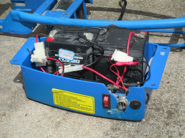
I wanted to start charging the batteries from my “new” scooter while working on other aspects of the project and the scooter didn’t come with a charger — I’ll deal with that later. Not knowing much about the wiring circuit yet, I didn’t want to connect an external charger to the batteries while they were still in-circuit and chance damaging the speed controller, so I needed to disconnect and remove them.

Wiggle wiggle wiggle <grunt> wiggle pull <grunt> WIGGLE WIGGLE BEND <grunt>

Wha?

Soldered battery clip

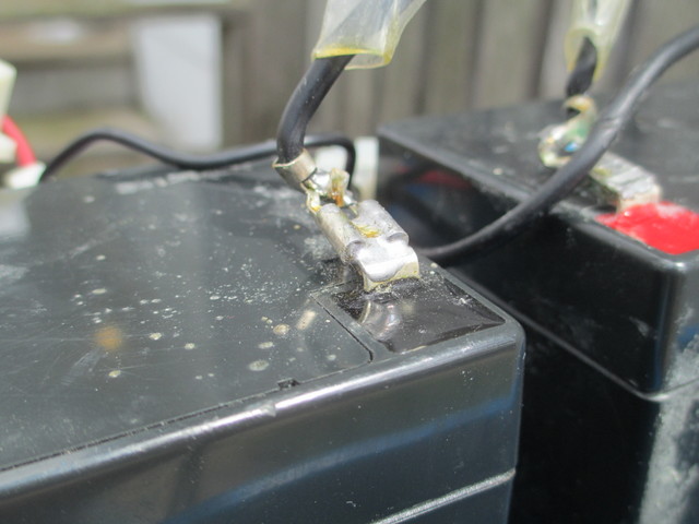
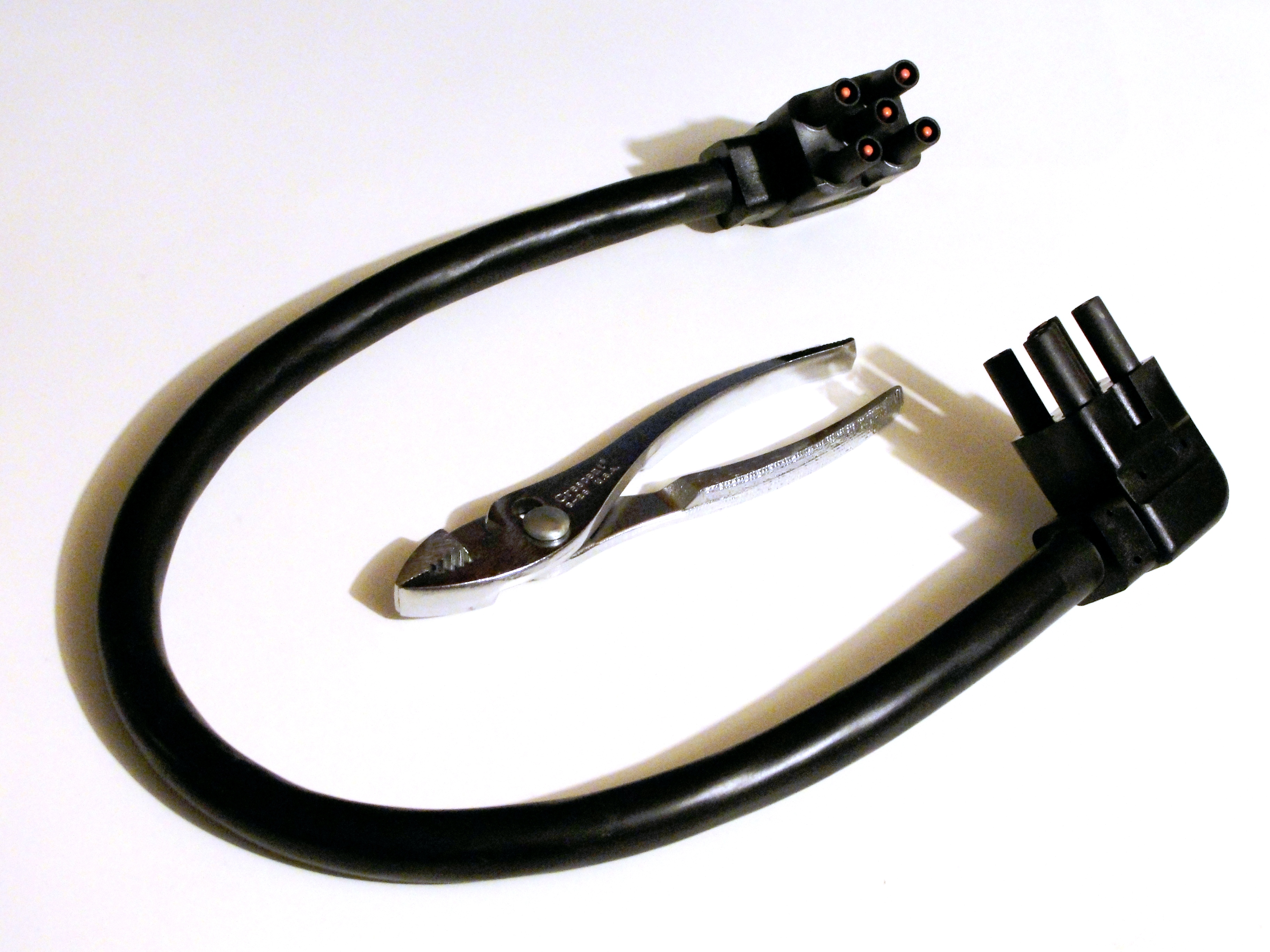
Who does this??? When they said solder the quick-disconnect terminals, they meant the wire side.

Fine. My uncle’s iron and a pair of pliers solved that problem.

Two sealed lead-acid batteries from Razor E100 scooter

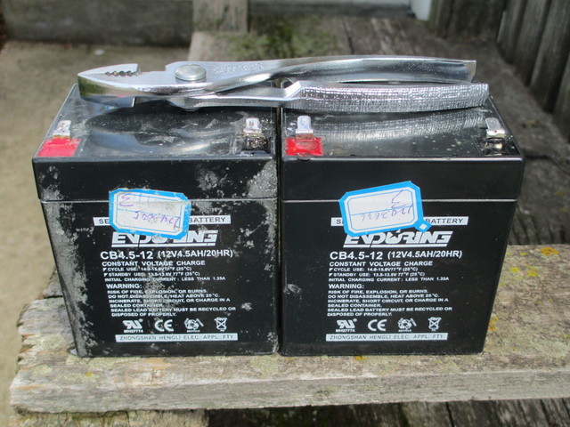
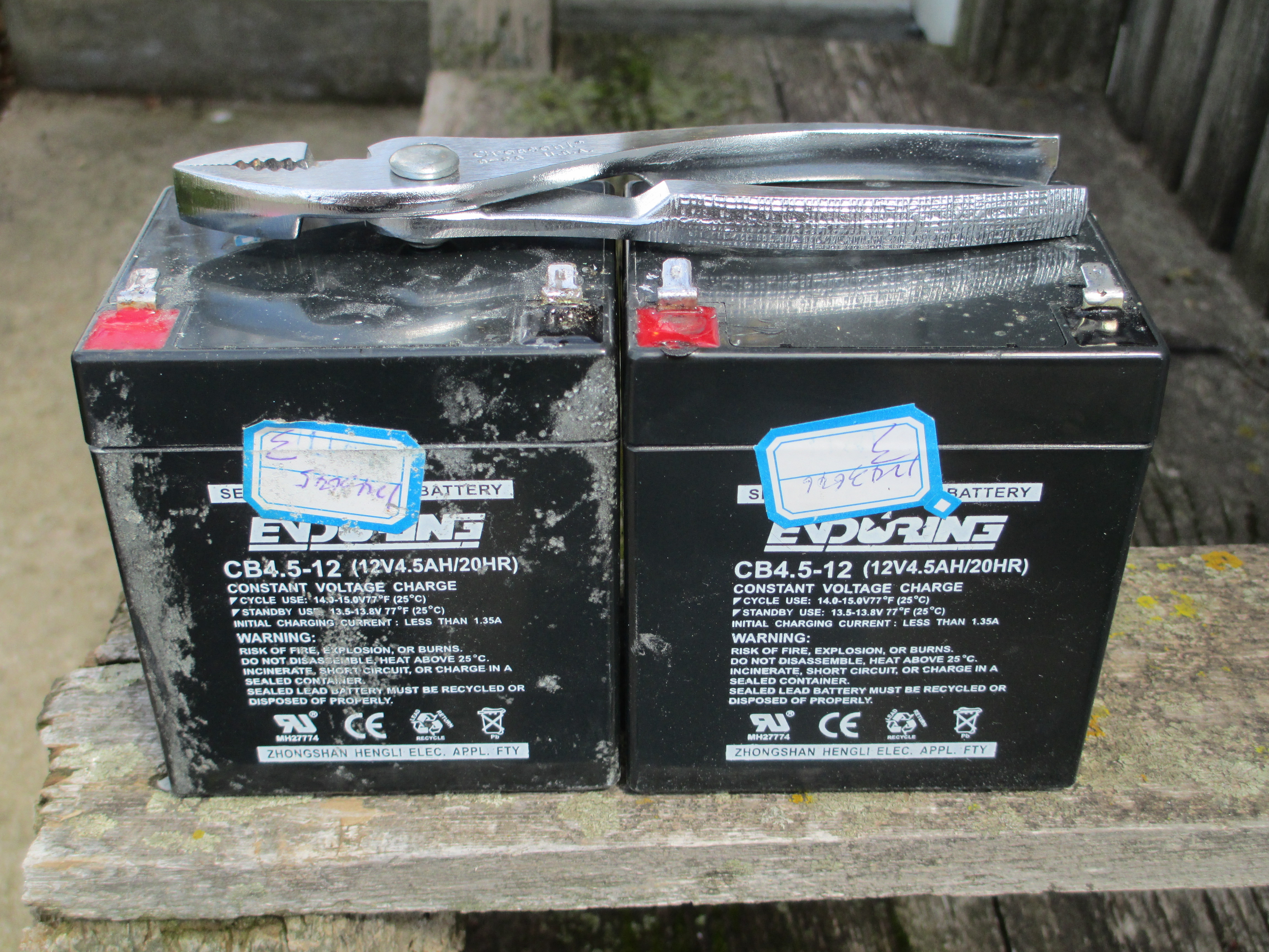
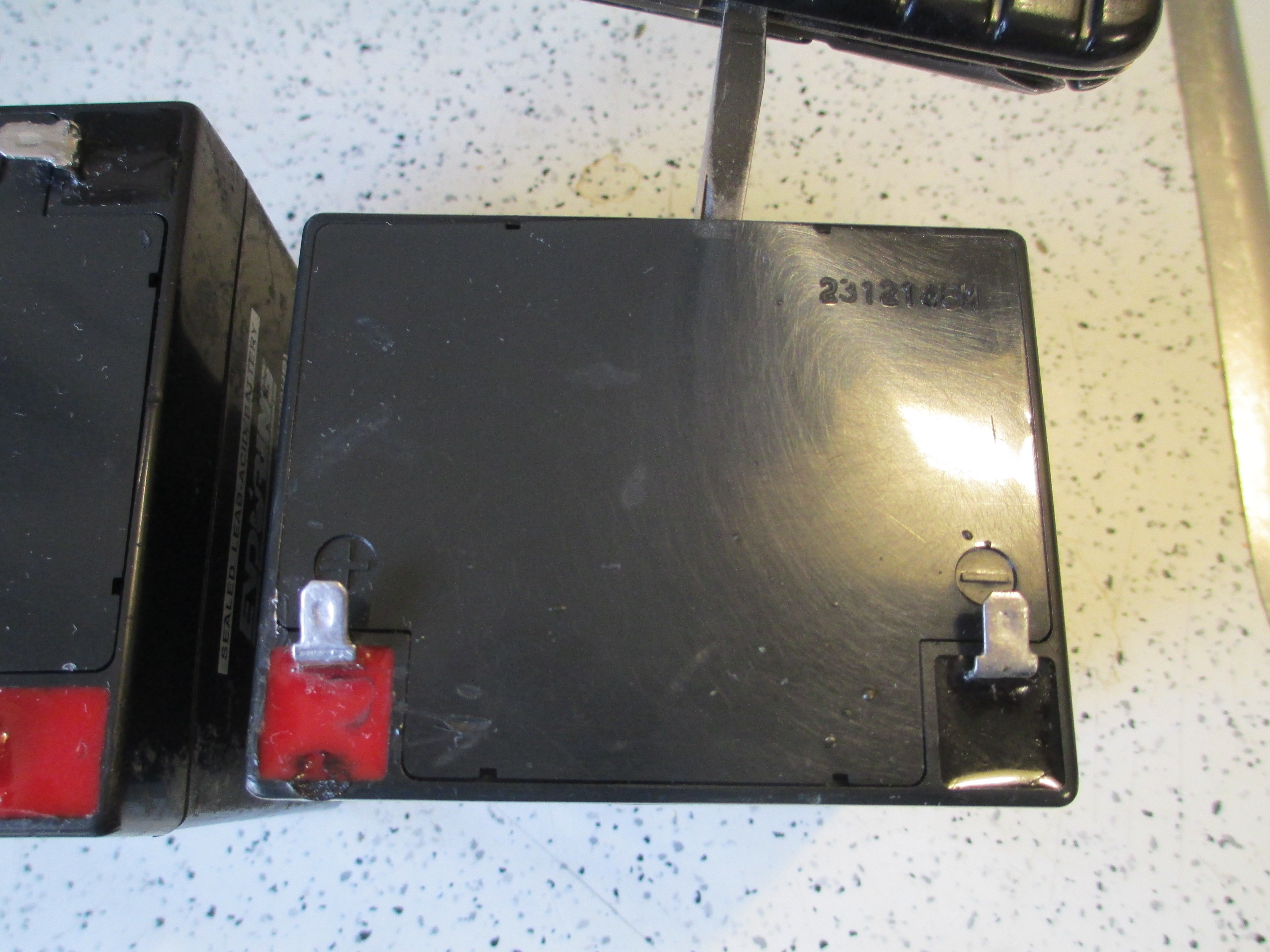
Two batteries, extricated and not yet cleaned.

Prying open sealed lead-acid battery cover

In spite of being “sealed,” you can pry off the cover (preferably after cleaning, which I did first with Goo-Gone and then with dish soap and water)

Sealed lead-acid battery cell caps

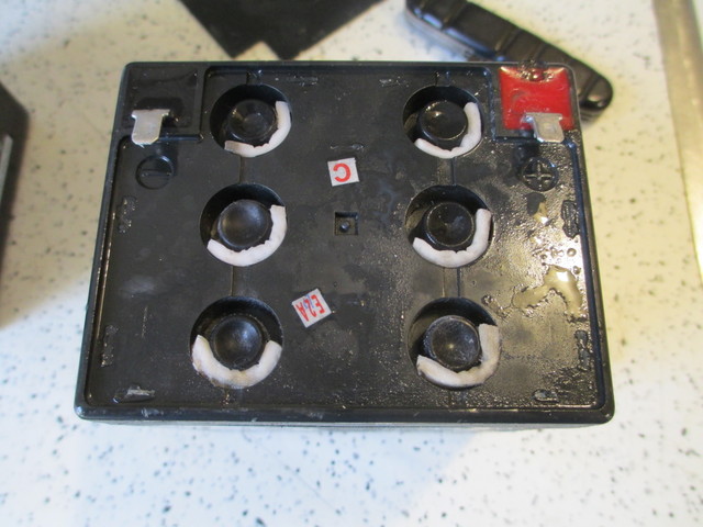
and get to the cell caps, each with a little absorbent pad in case the cell venting carries too much moisture.

I could see no water in any cell of either battery. I borrowed a jug of distilled water from my folks (I don’t know why Mom always has some, but she does) and started filling them up … after taking measurements.

Battery 1 Battery 2
Initial 11.68 V 9.99 V
After adding water 11.62 V 9.92 V

I filled each cell, waited for air bubbles to trickle to the top, refilled, waited, refilled, waited … I’m guessing between the initial fill and while charging, I ended up putting at least 10 ml of water into each cell.

Then put battery 1 on my variable power supply with the voltage set to 13.8 V and the current limited initially to 0.1 A, raising the current limit to 0.3 A as it was clear that nothing horrible was happening. I checked on it every half-hour to hour, frequently refilling at least one cell in which I could no longer see any water.

After about four hours, it was up to 13.5 V. The water level in the cells had risen to overflow the opening and fill each reservoir. If I watched long enough, I could see the water in a couple of cells <pop>, indicating they were just starting to gas and it was time for me to stop this method of charging for the day. (More on that on a subsequent day, hopefully tomorrow.)

Charging sealed lead-acid batteries with power supply

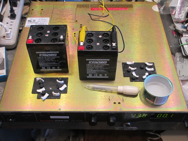
While battery 1 was charging, I was also checking water levels in battery 2 and refilling low cells, just sitting on the counter.

Recalling that it had an initial 10 V charge to battery 1′s 11.7 V, noting that they had been connected in series, and knowing that the worst cell in a battery generally has a cascading failure, I expected a different charging experience from battery 2, and I was quite right.

I connected it to the power supply and it immediately showed 13.8 V at a 0.1-A current draw. Now, about an hour later, it’s at 13.5 V and 0.3 A and most of the cells have overflowed. It’s nearly done charging but I haven’t put nearly as much energy into it as I was able to put into battery 1 — that is to say, it’s not “taking” as much of a charge.

Battery 1 Battery 2
Initial 11.68 V 9.99 V
After adding water 11.62 V 9.92 V
After charging 12.68 V 12.48 V

Tomorrow, schedule willing, a load test and an attempt at desulfation.

Why I don’t buy Duracell, Energizer, Eveready, or Rayovac

Saturday, February 18th, 2012

LED flashlight damaged by leaking batteries

I was given this high-quality, hefty, well-balanced, well-performing LED flashlight several years ago with batteries already in it. I keep it in the glovebox; and recently when I needed it, it didn’t power on.

Packages of DieHard AA and AAA alkaline cells

In my decades of using consumer electronics, there’s only one brand of alkaline cells that has never leaked in my equipment — even things I’ve forgotten about and found again years later — and I drive miles out of my way to buy them.

DieHard alkaline cell warranty

Doubtless someone will pop up with their own horror story, but I’ll still make the claim: You will never, ever, need this.

Cleaning the Flashlight

In order to get out the crud, I disassembled the flashlight completely and cleaned it with a wire brush, a wire wheel on the Dremel, a wire brush on the Dremel, and a toothbrush and dishwashing detergent. I went a little overboard to make sure I had got it all, but at every stage I was getting out more crud.

I’ve long been impressed with the heft and solidity of the flashlight; now that I’ve seen the inside, I’m equally impressed with its design and with the ease of (dis)assembly.

Element LED flashlight, disassembled

Loosely clockwise from the left, the reflector isn’t adjustable for beam focus but screws off anyway. The heatsinked LED has a separate plastic housing with beveled forward edge that centers the LED against the back side of its reflector cone. The LED housing’s retaining ring doubles as one of the LED terminals.

The aluminum head holds the LED housing and the separate LED driver housing, dropped in from the tail end, and screws tightly to the reflector. The plastic housing for the tiny power switch and LED driver board is made of two identical, completely reversible parts, holding in the inner power switch pushbutton on the one side and leaving a window to check board orientation for assembly on the other.

The rubber outer power switch pushbutton installs after the LED driver is dropped into the head and does not seal against the housing, suggesting that the o-rings on the aluminum housing are for a great feel during assembly and battery replacement rather than for water resistance.

The battery cage holds three AAA cells and assembles easily. The stiles are marked with the cell orientation; the filled cage looks a bit like a C cell and drops into the flashlight handle, with the spring-loaded button and the metal ring contacting corresponding surfaces on the bottom of the LED board.

The tail cap doesn’t make electrical contact with the battery’s negative terminal and the flashlight body doesn’t conduct current, as it does on many less expensive flashlights (not that I think I care).

Cleaned, reassembled, and with AAA cells reinstalled, it once again works perfectly. I look forward to many more years of service … and to not having to clean it out again.

Modifying a Harbor Freight Solar Charger

Tuesday, June 21st, 2011

My dashboard solar charger is one of the more useful things I’ve bought from Harbor Freight. My van has some weak short-circuit and slowly drains the battery, and as I don’t use the van all that often, I was at risk of coming out to a completely drained battery. I now keep one of these on the dash and the battery is always topped off. When I first connected it, the van was sitting in shade and the (old) automotive battery measured 5V (!); after a week it was up to 9V and after another week it was fully charged. Now I don’t ever have to think about a drained battery again. At about $20 list and $15 on sale, it’s a steal.

Harbor Freight solar charger model 44768

The bus conversion project is languishing but not forgotten, and I’ve been wanting to put one of these chargers into the bus for the same reasons as I had for the van. The wiring situation is a little different, though — the bus has no cigarette lighter / power port, I’m intending to wire 12VDC throughout the bus with Anderson power pole connectors, and I might like to have multiple solar trickle chargers (even before I install larger solar panels on the roof).

The issue with multiple panels, and even with a single panel connected to a battery that will also be charged by the alternator, and even with a single panel that may still be connected to the battery at night, is that photovoltaic cells don’t like to have reverse voltage applied. The photovoltaic effect happens in a semiconductor junction, and although I can no longer find the reference I was reading the other day, I still know the cell doesn’t do well with a reverse voltage and should really be diode-protected.

Because I wasn’t sure how much (if any) circuitry was in the panel and how much (if any) was in the automotive power plug connector, I had to take both apart to (A) make sure the panel would be diode-protected even after I chopped off the power plug and (B) see whether either held any relevant / useful circuitry.

(more…)

Stratasys ABS Rapid-Prototyping Machine

Monday, May 30th, 2011

Another heretofore unfinished old post, this one from January 2010:

I was over at the aviation department last week and happened upon the installation of a new Stratasys rapid-prototyping machine.

Stratasys ABS rapid-prototyping machine, front left view

It has a much larger build chamber than NIAR’s previous ABS machine — this one is something like 14″ x 14″ x 18″.

Stratasys ABS rapid-prototyping machine, left side open

The case was open and I was intrigued by the thick blanket of insulation around the build chamber. I asked the installer if the whole chamber was heated and he said yes, to 80°C. Interesting point of reference, as RepRap / CupCake owners seem to have settled on 60°C as the standard temperature for heated build platforms.

Stratasys ABS rapid-prototyping machine, hazy shot of extrusion head

It was fairly dark inside the build chamber and I couldn’t get a great shot with my cell phone camera, but you can see the extrusion head with two nozzles for support and build material. I found it interesting how extremely broad and shallow the white nozzle cones are — maybe it helps prevent snags?

Filament from Stratasys rapid-prototyping machine

With the lab manager’s blessing, I fished two filament strands out of the trash. The upper, black filament is ABS; the lower, translucent brown filament is a dissolvable support material that apparently washes out in an agitated hot water and detergent bath. Wish I knew exactly what it was!

I measure the diameter at .070″ ± .001″ ≈ 1.778mm ≈ 1.75mm ≈ .069″, so it looks like they’re using 1.75mm filament. The stretched section on the end is recognizable as having been in the hot end and then backed out.

Note the toothmarks all the length of each filament (about 3m), suggesting that either something is pushing the filament from that far back or (more likely) the hot end has a quick-release for cleaning and this filament was run through the machine after removing the hot end.

Solar Charging and Switching Circuit for Outdoor Sculpture Installation

Sunday, May 29th, 2011

Over the winter, my friend Steve Atwood got a commission for a sculpture to be installed in the Wichita Falls, TX Kemp Center for the Arts “Art on the Green” sculpture garden from May 2011 – 2012.

Lure 22 V2.0 by Stephen Atwood at Kemp Center for the Arts, Wichita Falls, TX

He had in mind to continue a series of his sculptures based on the form of a fishing lure but wanted to enhance this sculpture with one or more LEDs, preferably that would come on only at night. We discussed a wide variety of options that we hope to develop for another installation in the future; but in the end, in the interest of time for this project, Steve found control modules that flash up to five LEDs at random and installed them behind a set of cones protruding from a recessed panel.

He asked how to make the LEDs turn on at night and also wondered whether he could power them for a year from a primary battery or whether he should use rechargeables.

Lure 22 V2.0 by Stephen Atwood at Kemp Center for the Arts, Wichita Falls, TX

About seven years ago, I had come into possession of some discarded solar yard lights, and out of curiosity had reverse-engineered their charging and control circuits. Since yard lights accomplish both functions — charging and switching — I figured the circuit would be perfect for the sculpture. I was able to find one and instruct Steve how to modify it for his needs.

Solar yard light schematic

The circuit is very simple and I find it rather elegant. During the day, the solar panel assembly (left — for want of a proper schematic symbol, I just drew another battery) charges two AA cells through a diode that prevents the battery from damaging the panel with reverse voltage at night. Additionally, through the R1 – R2 voltage divider, the solar panel pulls up the base of Q1, switching it off and allowing R3 to pull up the base of Q2, switching it off and switching off the load LED1.

At night, the panel’s output approaches 0V and R2 pulls down Q1‘s base, causing Q1 to conduct and pull down Q2‘s base (in a Darlington-like arrangement — I don’t know whether it’s still considered a proper Darlington with R3 pulling up the Q1 emitter – Q2 base connection), switching on Q2 and LED1. In fact, depending on the panel’s exact voltage, the load may switch on even before full darkness, and R1 – R2 can be tweaked to tune the turn-on point.

Control board from solar yard light, modified

Steve removed the LED from the control board and replaced it and the fly wires for the solar panel and battery with screw-terminal connectors for ease of installation inside the sculpture. He bought a new solar panel with a higher output voltage to charge the higher-voltage battery for the white LEDs he wanted to use (the yellow LEDs in my yard lights didn’t require as high a forward voltage) and milled a Lexan cover for it to protect the panel from hail, with an O-ring groove to protect it from rain as well.

With higher battery and solar panel voltages, Steve indicated the load was turning on before the ambient light got as dark as he wanted, so I told him how to locate R1 and replace it with fly wires to a 100K pot. After the swap, he said he was able to tune it perfectly and he was delighted.

Lure 22 V2.0 by Stephen Atwood at Kemp Center for the Arts, Wichita Falls, TX, night view

I’ve not had a chance to visit the sculpture garden and probably won’t while Lure 22 is installed. If anyone’s in the area, I’d love to hear from you how well it’s working and how well the electronics hold up over the course of a year outdoors.

Liebert Battery

Saturday, May 28th, 2011

Just found this unpublished draft from October. I had received a GXTV2-48V battery expansion cabinet for my Liebert GXT2-2000RT120 UPS and wanted to see what was inside.

Liebert GX2-48VBATT battery cabinet interior

Eight sealed lead-acid batteries are bolted down and connected through a circuit breaker / switch to the two input/output jacks in parallel.

Liebert GXT2-CABLE48V1 UPS battery cable

The cable to daisy-chain the battery expansion cabinets to the UPS is … substantial.

installed

Installed in the basement server rack (bottom) and connected to the UPS. Sure wish I had a bezel for the battery cage.

Modifying a Car USB Adapter to (Finally) Charge My Cell Phone

Saturday, May 28th, 2011

A couple of years ago, I received this automotive USB-connector power adapter as a promotion at a conference. I use it to keep my iPod nano charged in the car, but I’ve noticed it doesn’t charge my Blackberry well. To be precise, it doesn’t charge my Blackberry. In fact, I’ve never been clear whether it even slows the rate of discharge, and sometimes it seems like it speeds it. The Blackberry shows the lightning bolt charging symbol (The charging symbol is a lightning bolt, srsly? Ben Franklin is personally charging my phone?) but nobody’s home.

Note that I don’t blame the vendor whose logo happens to be on it — I’m sure they didn’t manufacture it.

Automotive USB power adapter

After driving two and a half hours a week ago starting with a half charge on my BlackBerry, plugging it in midway through the trip, and arriving to have the BlackBerry finally shut off its radio due to depleted charge; and due to being in the presence of Cort; I decided it was time to see why the adapter couldn’t provide enough charge for the BlackBerry.

Inside the Power Adapter

Sample step-down circuit using RT34063APS DC-DC converter

(more…)