Archive for April, 2007

Fire Alarm Dialer

Saturday, April 28th, 2007

What shall I do with this?

Fire alarm dialer box, front

You know your reputation as a salvager is increasing when the campus fire chief walks into your office and says, “I hear you might be interested in this.”

Yes. Yes I am.

Fire alarm dialer box, open

It’s a Microtel automatic dialer, built to watch a variety of analog and digital inputs, dial telephone numbers in response to alarm conditions, and play recorded and/or synthesized messages. It was installed under the floor of our data center, and apparently at some point its power was disconnected. After the backup gel battery drained, the voice card lost its mind. It’s old enough that they decided to replace the whole unit rather than the voice card.

Fire alarm dialer box, interior

The upper row is the system bus, containing the power supply, the CPU card, a voice memory card, and a telephone interface card. I’m not sure yet what the other card is. The lower row is the I/O bus, with two digital input cards.

What to Do?

I think it’s pretty cool. It’s a really nice enclosure. I love the LCD on the front panel, which looks like it has a parallel interface that should be easy to hack. The cards are intriguing, particularly if one of the chips is a voice synthesizer. The power supply offers 5V and 12V, and already knows how to charge a gel cell and cut over to it when power fails.

But I’m surprised at the enthusiastic response I’m getting from non-electronics-geeks. The normally reserved Garrett positively gushed over it, and today my friend Jonathan (ER nurse and fix-it guy) expressed how awesome it was, and how many cool things you could do with it.

All right, then, you tell me. What should I do with it? Enclosure, components, or the works?

Stepper Motor Controller Board

Sunday, April 22nd, 2007

Keeping a blog is a great way to realize exactly how long some of my projects sit on the shelf–until recently, I haven’t worked on my CNC milling machine project since last May. Hoo boy.

Last time I discussed it, I’d been experimenting with the stepper motors I want to use to drive it, and the last thing I had done was build a driver out of discrete, complementary MOSFETs. I was hitting about 500 steps (2.5 revolutions) per second, and the output transistors were getting pretty warm. Plus I was using a 12V supply to feed the motor’s coils that only want about 2.1V each, so I was throwing away the rest of the voltage in huge sand resistors.

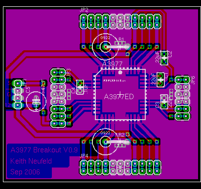
Allegro A3977 Stepper Driver

I was interested in trying a dedicated stepper controller chip, and I found the A3977 microstepping driver chip from Allegro Microsystems. It’s rated for 2.5A per coil (the same as my motors) and looked perfect for my application, so I ordered a few samples.

The A3977, like many other current-controlled drivers, has each load (motor coil) in series with a sense resistor, to measure the current actually flowing through the coil. The A3977 ramps up the load voltage until the sense voltage reaches a (designer-controlled) threshold, then shuts it off and ramps again. Thus the average current through the coil (when energized) can be controlled by the combination of sense resistor value and reference threshold voltage.

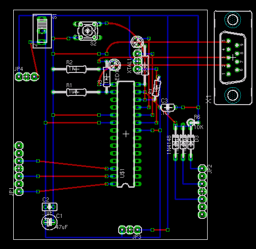
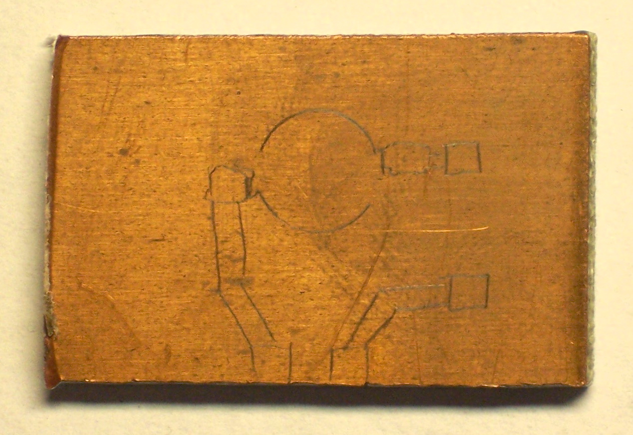
Clear back in September (ahem), I laid out a breakout board for the A3977, to make sure I understood how to control it before building real control boards for the CNC machine. I put on header sockets to make it easy to try different parts values; about the only parts soldered onto the board are the A3977 itself and several required capacitors whose values are specified on the datasheet.

I also planned to solder the sense resistors; their resistance is so low that an oxidized socket could add resistance equal to a significant fraction of the resistors themselves.

A3977 breakout board

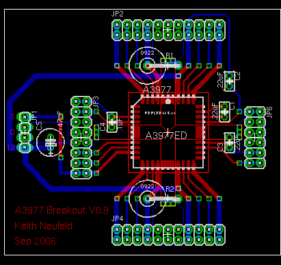
The biggest challenge in the layout was designing adequate heatsinking. The A3977 doesn’t have a solder pad on its belly, and I’d have had a hard time soldering it even if it did. Instead, the three pins at the center of each edge are ground pins that double as heatsinks, and they want a big copper area for dissipating heat.

I used EAGLE’s polygon feature (I think that’s what it was called; I should have taken better notes while I was doing this) to make big copper areas. In the above picture, the brighter red and blue outlines show areas that will be filled with copper on their respective sides of the board.

A3977 breakout board with polygons filled

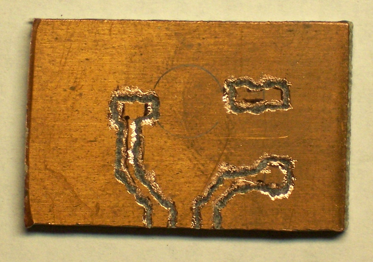
Hitting the ratsnest button then flood-fills copper into not only those areas, but the rest of the board, leaving a specified gap between the copper ground plane and any pins not specifically identified for inclusion. Since I was planning to etch the board in the sink, leaving large copper areas not only provides the requisite heatsinking, but saves on etchant and etching time.

Building the Board

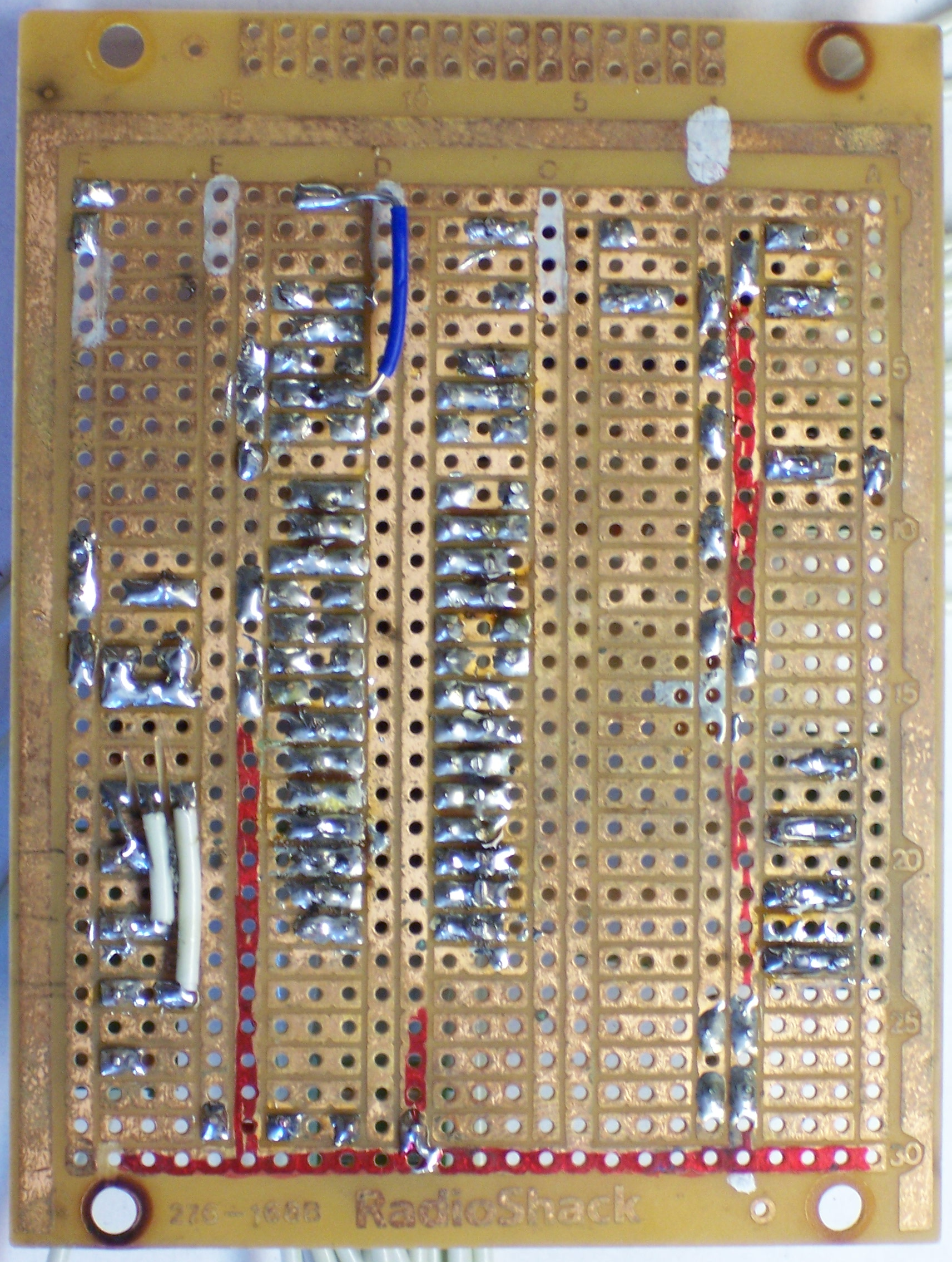
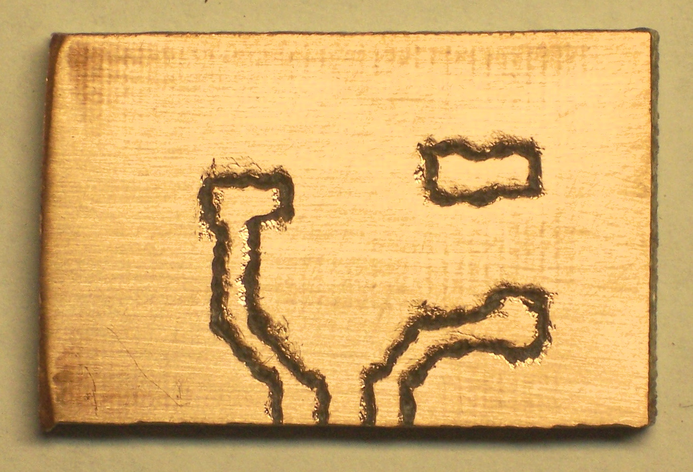
Immediately after making the board, I got the A3977 soldered onto it. Because the board was hand-etched, it was a lot dirtier than professionally-manufactured boards, and soldering the big PLCC chip onto it was correspondingly more difficult. But I got all good joints and no bridges, as confirmed with the continuity tester.

And then the board sat from September through April. Sigh.

A Kick in the Seat

A few weeks ago, I suggested to John Harrison that we needed to get back into having a “geek club” meeting every Monday night this summer–and that at every meeting, every member had to show or demo significant progress on some project. It’s amazing how much you can get done when you have peer expectations of continuous achievement.

I called John on Friday evening and told him that I needed a pep talk: I had a wide open weekend and two electronics projects that I could work on but was reluctant (and/or intimidated) to start. I could finish the work and blog on repurposing a battery-operated motion sensor (coming soon) for class, or work on my stepper controller.

He asked which one I was going to show him on Monday night. Well!

That was the motivation I needed, even though it turned out he’s out of town Monday. By the time I went to bed Friday night, I had the whole board assembled (except for the pieces I forgot). Instead the motor running, though, it kind of twitched and buzzed.

I reread the datasheets and applications notes as I was going to bed, and realized I had somehow left out the RC components for the output waveform generators. My wife woke me up at 6:30 Saturday morning for help with the laser printer before running off to manage the local food coop’s distribution day, and by the time normal people were up, I had the controller running the motor at full speed.

Stepper motor controller board

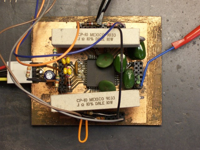
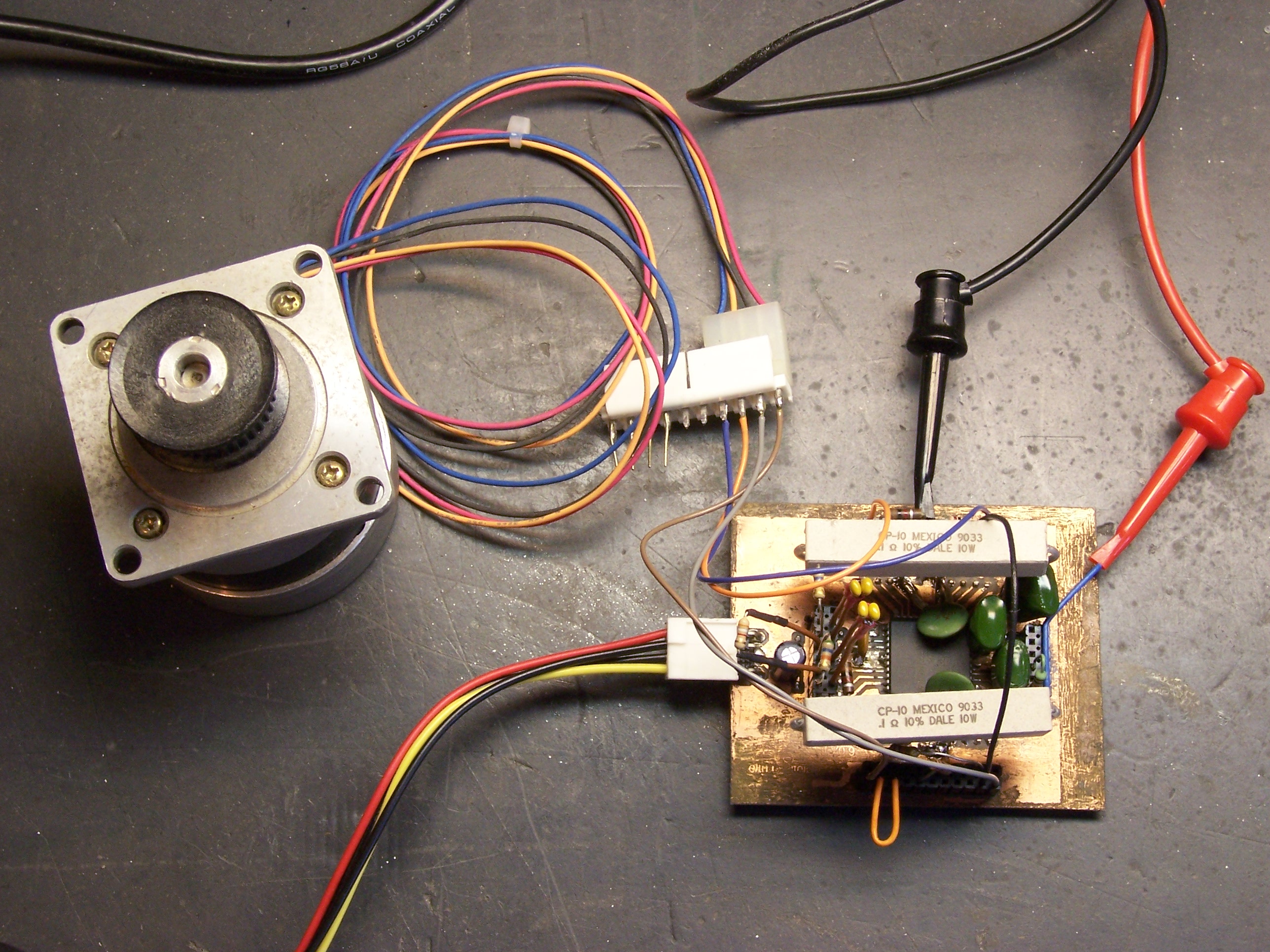
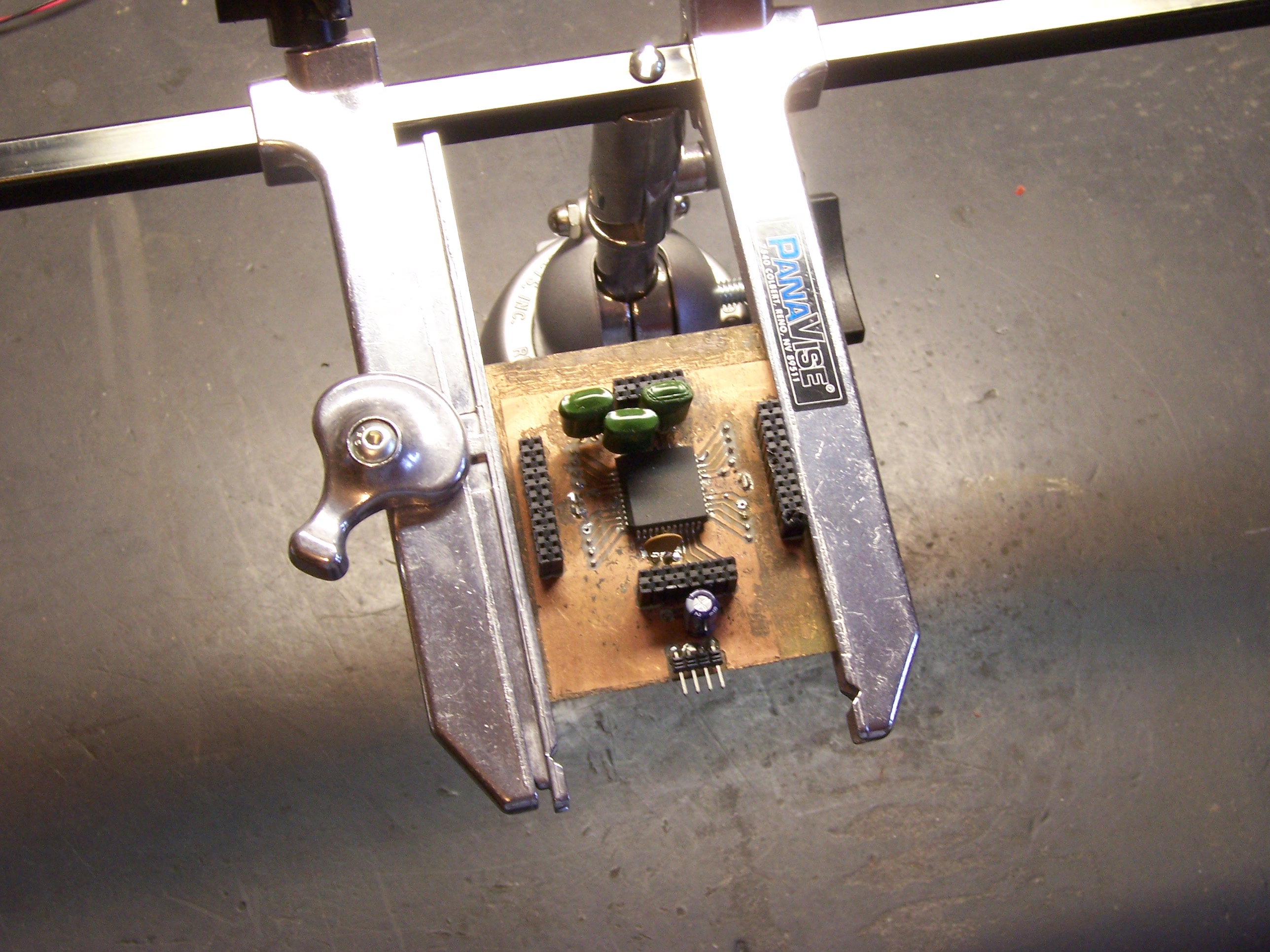
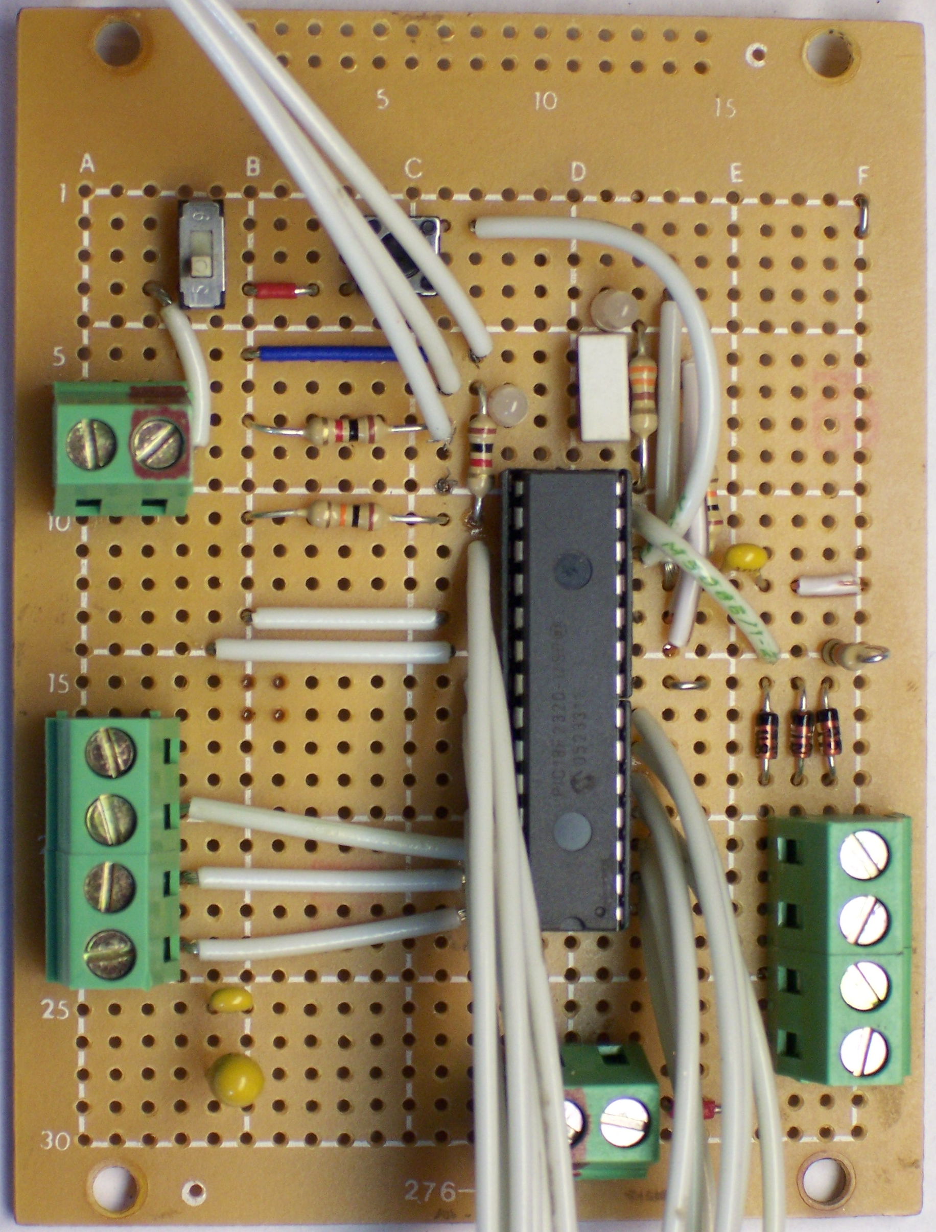
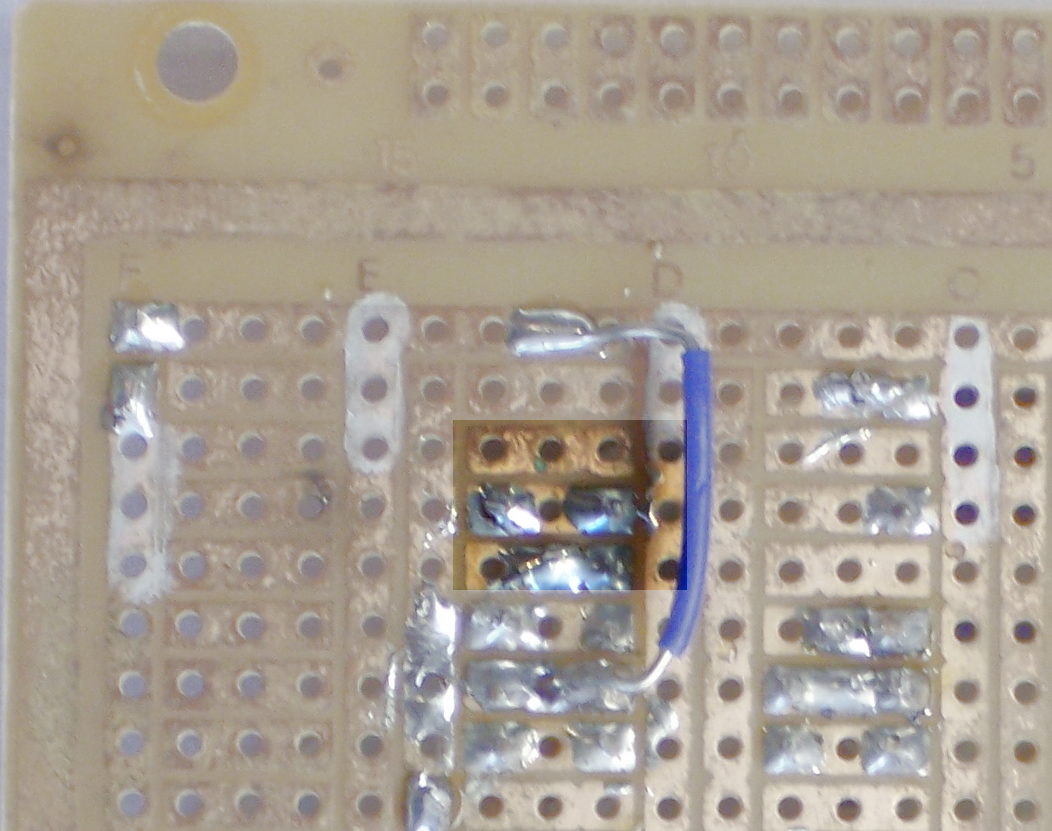
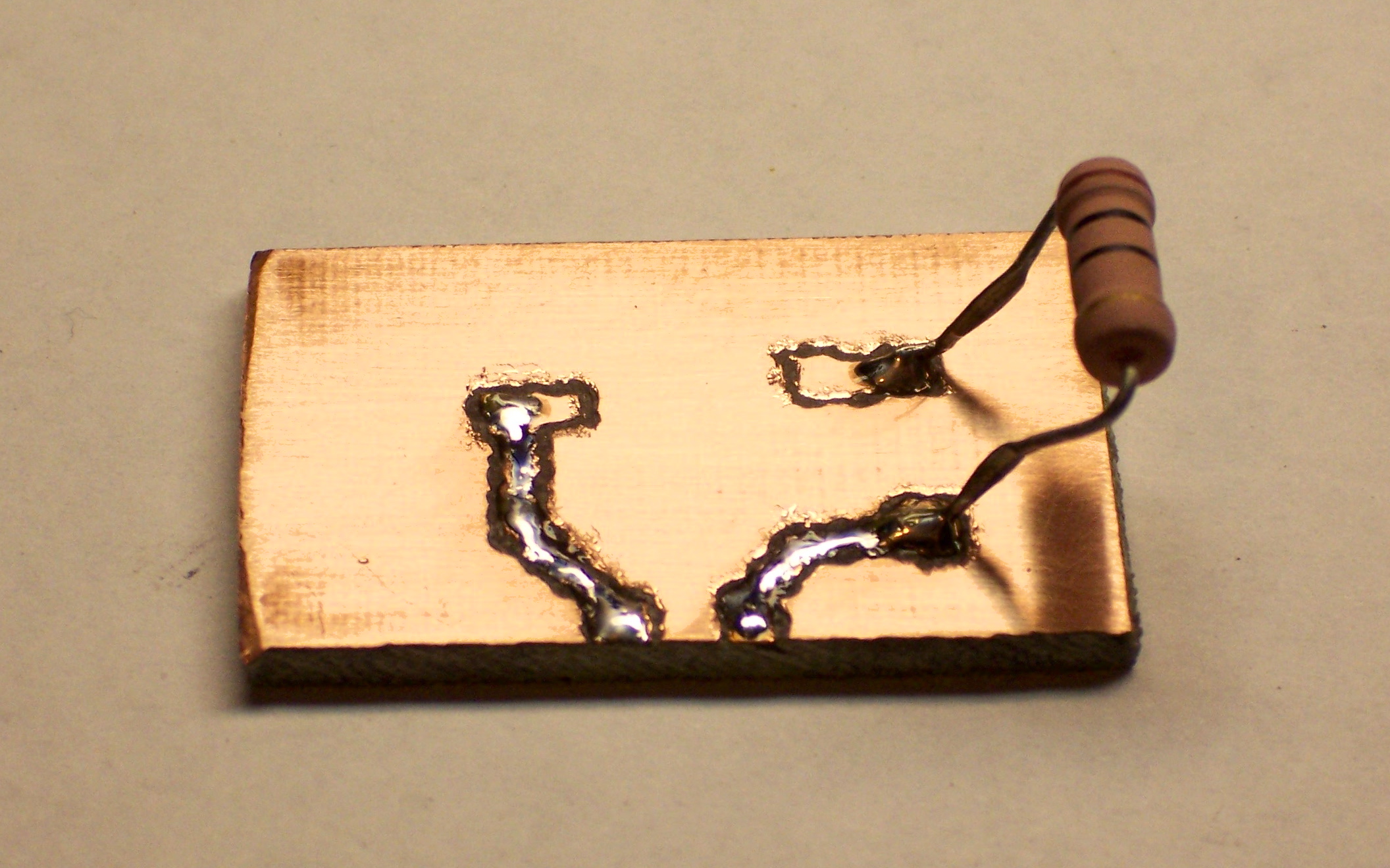
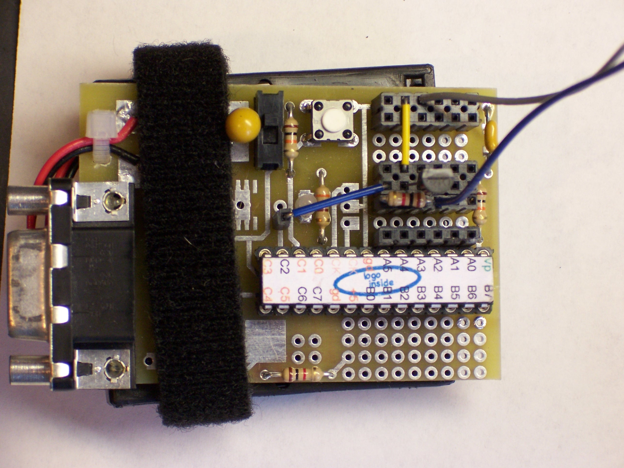
Here’s what the board looks like with everything installed. The big sand resistors are the sense resistors–and yes, that is .1Ω (although I tried .2Ω first and will probably go back to it). The weird green things are capacitors for an internal voltage boost circuit. The motor coils are fed from the orange, blue, brown, and grey wires that take off from the upper and lower corners. Power from a PC power supply comes in the left, and the red probe and blue wire on the right provide a step signal from my function generator so I can test without hooking up a microcontroller. The extra wires and resistors around the outside are jumpering things like /RESET, /ENABLE, and DIR, again to facilitate μcontless testing.

Stepper motor controller

Thar’s what it looks like with the motor.

How It Works and Lessons Learned

Speed

I was surprised that I wasn’t able to get it to run faster than it does. I haven’t measured exactly, but I guesstimated I was hitting about 600 steps per second (3 revolutions per second) before it started jittering instead of turning. I tried half- and quarter-stepping (at correspondingly higher clock rates), hoping the smoother drive would increase the maximum rotation speed, but it didn’t. I swapped out the sense resistors to increase the motor current, but that didn’t increase the maximum speed either. I could tinker with the ramp generator’s RC values, but I don’t think that’ll help either. The controller is rated for 600,000 steps per second (!!!), so I’m pretty sure the limitation here is the motor, and I’m just pushing it as fast as it can go.

That’s a little disappointing, because (1) that’s only a little faster than the 500 steps/second I was getting with my MOSFET driver; and more to the point, (2) with a 20 thread per inch lead screw, 3 revolutions per second works out to about seven seconds per inch of travel. That is, if the cutter head is at the opposite side of a sheet of typing paper and needs to come back, it’ll take a minute for it to travel across. That’s pretty painful.

The documentation at the LinuxCNC (née EMC) web site suggests that high-speed CNC machines use DC motors with optical encoders, rather than steppers. I guess I’ll look into that for version n + 1.

Advantages?

I’d been hoping that the current-control system would be the silver bullet that pumped this motor up to dramatically higher speeds. Since that’s clearly not the case, is it still worth using this chip over the discrete MOSFET design I made?

I say yes. The A3977 is much smaller than the eight TO-220 FETs (plus heatsinks) required in the discrete transistor design.

The A3977 also runs a lot cooler. Its temperature rose to the mid 90°F range after several minutes of continuous full-speed operation. In contrast, the FETs got hot enough to burn fingers (I didn’t have my infrared thermometer yet) after only a few seconds of operation.

Allegro would claim that the A3977 also improves the pin count for processor interfacing–it requires only two pins (direction and step), whereas the discrete transistor solution requires four pins (two wires each for two coils). This is probably valid, although the plethora of options (half-, quad-, and eighth- stepping, reset, etc.) will tempt me to use up those saved pins controlling other facets of the stepper operation.

Sense Resistors

I had ordered big sand resistors with thoughts of stacking them to kill voltage in my MOSFET design. But defining ITRIPMAX as the maximum instantaneous current of each output ramp cycle (in my case somewhere between 2.5A and 5A), the A3977 recommends:

VREF = 4V
RSENSE = VREF / (8 * ITRIPMAX)
      = 4V / (8 * 2.5) = .2Ω

Which is what I’m using. BUT working back:

V = I * R
VR = 2.5A * .2Ω = .5V

P = V * I
P = .5V * 2.5A = 1.25W

So the resistors need to be large, but not quite so monstrously huge. (These are 10W.) I’ll shop for smaller ones before building the real board.

PC Board Vise

Sunday, April 22nd, 2007

I’d heard that PC board vises were the cat’s meow for stuffing and soldering boards, and I’ve seen them used in a couple of “how to solder” videos. So when my friend Cort was putting together a big parts order recently, I had him add on a vise for me. Here it is.

PCB vise

It came in pieces: the base, the spindle, the bar, the clamps, and all the knobs. Pretty easy to put together, but I had one little problem:

PCB vise with misaligned jaws

The jaws didn’t line up. Like, so bad there’s no way I could make a decent PCB stay put.

The square holes to fit over the bar had casting flash left in them; and the bar itself is rhomboid instead of square, so it doesn’t fit snugly into the jaws’ (allegedly-)square corners. It was even possible to wiggle the jaws and make them misalign in the other direction, but not to get them to stay aligned.

PCB vise with realigned jaws

So earlier this weekend, I sat down with a square file and got all the flash out. I also found which way the clamps fit best on the bar and reoriented them to that position. Now they’re stable and pretty well aligned.

PCB vise holding my stepper control board

I got to use it for soldering some of the last components of my stepper control board. The vise’s spindle has a joint that folds 90° forward or back, so I assembled it to have the jaws pointing straight up when the spindle is straight. I fold it forward to do top-side work, and then fold it back up and over backward to do bottom-side working. Verra nice!

Nightmare Workbench

Sunday, April 22nd, 2007

My workbench

I think it might be time for me to tidy a bit.

Rice Krispies Five-Digit Counter

Thursday, April 19th, 2007

Look what my wife found in a Rice Krispies box!

Mickey Mouse step counter from Rice Krispies box

It’s a five-digit counter module! Oh, it’s supposed to count your steps while you walk around at Disneyland, but why shouldn’t it be able to count other things???

Okay, let’s do it.

Digging In

Here’s the back side of the case.

Counter case, back side

OH NOES!!! Triangle-drive screws! Whatever shall we do???

Security bit set

:-)

Counter, interior view from above

Here’s the inside. The metal arm at the upper left has a small weight, nearly balanced by the hairspring. It bobs up and down when you walk, making contact on the downstrokes with the metal tab at the corner of the PC board.

Counter, interior view

The Guts

After removal of the two screws holding down the weight, the active electronics pop out–still running.

Counter module, extracted

Disassembling the screws from the back of the PCB enables it to be separated from the screen.

Counter PCB and screen assembly

Note the anisotropic strip on the LCD. It looks like a strip of rubber, but conducts electricity only in the direction of its width (which is oriented vertically here). It interconnects the display contacts on the PCB with the contacts on the LCD, just by virtue of being squeezed between them.

Counter module, back side of screen

Mickey, Meet Jack

It’d be nice to be able to continue using this as a pedometer, but connect something else to count. And it’d be nice if connecting something else disabled the internal counter so you didn’t get extra counts from bouncy bouncy, right?

So we need a closed-circuit jack. It feeds a default signal to the destination, and disconnects the default when you plug something in. Think of plugging headphones into a receiver and it shutting off the speakers . . . or plugging a headset into a cell phone and it disabling the built-in earpiece and mike.

Main board from Motorola cell phone

[A few frustrating minutes with a good soldering iron and a bad piece of solder wick later . . .]

Closed-circuit jack from Motorola cell phone

The jack. Or in French, Le Jacques.

According to my continuity meter, the connections closest to each other on each side are normally closed (NC), and open to break the connection when a plug is inserted. The ones nearest the plug end make connection with the plug, and the ones furthest from the plug end get disconnected.

This jack is made for a stereo plug (common plus two wires), but we only need mono (common plus one wire). Which of the contacts touches the tip, and which the sleeve? I don’t know! We’ll connect both!

Counter case with jack fitted in place

Hold. Mark. Drill tiny. Enlarge. Enlarge. Enlarge. Step-drill. Step-enlarge. Step-enlarge. Voila! Or in French, voila!

Counter case with jack fitted in place, end view

Mickey, Meet Wire

Hum tiddle-um, time to do some wiring. Need to break the connection on one side of the weight-switch and reroute it through the default (NC) pins on the jack. The big metal strip that the weight hits is pretty directly connected to what turns out to be the + power lead, so it’s easier to interject into the hairspring’s connection (the big solder blob in the lower middle).

Counter PCB with trace cut and cleaned

Scrape, scrape, scrape, scrape, scrape. Clean the green varnish off the trace. Then cut the trace (just above the mounting hole).

Counter PCB with fly wires attached

And solder on some fly wires to go to the jack. I knew that my leftover wire wrap would come in handy someday. One piece to each side of the cut trace, and one piece to the + power supply (to take the place of the weight switch).

Counter module, rewired

After some notching of the LCD case (more than was intended, thanks to lack of planning), the module can be closed back up. I highly recommend putting the battery connector in the wrong place, so there can be more takey-aparty and putty-back-togethery. Then wire to the jack, connecting to both sides as mentioned earlier. (See the bare wires running across the left end?)

Or in French, Voilalala!

Counter, reassembled with new jack

One completed, rewired, general-purpose, five-digit decimal counter.

Debugging a LogoBoard

Wednesday, April 18th, 2007

After the 2006 Technology: Art and Sound by Design final exhibit, Steve Atwood worked on building his own LogoBoard to use in his sculpture. He found that his board wasn’t working and was overheating, and asked for my help troubleshooting it. To my recurring shame, I’ve had his board ever since with very little progress to show for it. Time to rectify that.

The Board, the Symptoms, and Initial Efforts

Steve Atwood's LogoChip prototyping board

Steve built his circuit on a prototyping board with a .1″ perforated .1″ grid and connecting traces on the back, much like a solderless breadboard. The PIC microcontroller is in the center, with various components, connections, and wires surrounding it.

The main thing I knew when Steve gave me the board was that the LogoChip was overheating. I measured the resistance from the LogoChip’s power pin to ground pin and got some very low value like 4Ω, so I knew something was broken, but not dead shorted. I replaced his chip with one of my own and tested again; mine overheated and had the same resistance as well, so his problem wasn’t just that his chip had burned out.

And there it sat for a year.

Drawing the Schematic

In order to do any further debugging, I needed to determine and draw out exactly what was connected where, so I could examine the schematic and find what looked amiss. And the easiest way I’ve found to make a schematic from a PC board is to recreate the circuit in design software, building out the schematic and a reproduction drawing of the physical PC board at the same time. When the traces on the board drawing match the traces on the board, the schematic is correct and complete.

Working with two windows in EAGLE, I created a new project and added all of the components from Steve’s board. I had to fudge on the screw terminals and the crystal oscillator because I didn’t have library parts for them; but for a quick job like this I feel okay substituting a .1″ header and simply remembering what’s really going on. I carefully placed each component on the PCB diagram at the exact space corresponding to its placement on the real board.

LogoChip prototyping board, back side

Once I had the parts placed, I turned to the back side of Steve’s board and began tracing connections. I added a connection on the schematic for each connection on Steve’s board, switching frequently to the PCB editor to draw out the physical path of the traces whose connections had been entered so far. I drew it as a double-sided PCB; where Steve had jumper wires on the top, I made a via and drew a top-side trace.

PCB layout of Steve Atwood's LogoBoard

When I was finished, I had a fair facsimile of Steve’s board. Oh, there were some messy bits where jumpers overlapped and fly wires left the board, but it wasn’t too bad.

Schematic of Steve Atwood's LogoBoard

And more to the point, the schematic made it fairly easy to identify the problem. There are blocks of the circuit whose functionality isn’t identified (although it’s fairly easy to determine). But they’re not where the problem lies.

If you look closely at the power wiring to the PIC chip, you can see that it calls to have ground wired to pins 8 and 19 and V+ only to pin 20; but instead, ground is wired only to pin 19 and V+ is mistakenly wired to pin 8 in addition to pin 20.

Voila! Problem solved. Well, identified, anyway. I’ll leave it to Steve to rewire that.

Solder Splash

One more thing. When I was tracing the connections on LED2, the “run” light, I noticed solder splash between its upper pin and the ground bus. It’s at the right edge of the highlighted area, trying to hide underneath the blue jumper.

Solder splash on prototyping board

I haven’t checked it with a continuity meter, but it should be cleaned up to be safe. If I’m correct that it’s shorting the two wires, then the bicolor LED would still light one color (green or red) when port C3 (pin 14) is raised; but would remain dark when port C0 (pin 11) attemped to raise but was shorted to ground.

And with that, the board’s ready to go back to Steve.

CdS Photocell

Tuesday, April 17th, 2007

A cadmium sulfide (CdS) photocell is a passive component whose resistance decreases when light shines on it. CdS photocells can be used to detect when lights turn on, to orient things toward a light source (electronic sunflower), and to detect shadows passing across them.

CdS photocell

To use a CdS photocell, you put it in series with a resistor and put a voltage across them. This forms a voltage divider: the voltage at their junction is determined by the proportion of the two resistances. If you want brightness to increase the measured voltage, put the photocell on top; if you want darkness to increase the measured voltage, put the photocell on the bottom.

Circuit diagram showing two ways to connect a photocell

All that remains is to determine an appropriate value for the complementary resistor. Assuming you want output voltage to increase when brightness increases, the goal would be to make the output read as close to 0V as possible when it’s as dark as you expect it to be, and as close to your maximum voltage as possible when it’s as bright as you expect it to be.

To begin this calculation, I measured the resistance of the photocell (out of circuit) in light and dark conditions. With the photocell shown above, I found the following values:

450KΩ in the dark (my finger pressed over it)
36KΩ in average light
7.6KΩ in bright light (under my fluorescent desk lamp)

I discovered later that the photocell’s carrier PCB isn’t entirely opaque and a noticeable amount of light does leak in around the edges even when the face is covered. The resistance in true darkness would probably be even higher.

I decided to scale the photocell’s circuit to the range from darkness to normal room lighting, so calculating for a resistance range of 450KΩ to 36KΩ. Because this is only a single order of magnitude variation of resistance, I could already tell the voltage swing of the output wasn’t going to be as large as I’d like. I picked a 100KΩ resistor and estimated the voltage range:

5V * (100KΩ / (100KΩ + 450KΩ)) ≅ .91V
5V * (100KΩ / (100KΩ + 36KΩ)) ≅ 3.7V

So it has a swing of about 3V out of a 5V range. Not ideal, but it still provides a fair amount of resolution.

Finally, I connected the photocell to my LogoChip’s A0 input and confirmed its behavior by running print read-ad 0. I got a wide range of values out of the A/D converter, making this circuit quite usable for microcontroller interfacing.

I also posted a cookbook version of using the photocell on the TASD class wiki.

Making Googly Eyes, Part 2: Construction

Monday, April 16th, 2007

As noted in Googly Eyes Part 1, I built a demo back in February out of a CD-ROM drive optical sled assembly and a couple of ping-pong balls. In the earlier installment, I discussed reverse-engineering the sled’s electrical connections; now here’s how I rebuilt it to operate eyeballs.

I had thought I might find some googly eyeballs in the Wal-Mart craft department, for making big puppets or something. But all their googly eyes were the flat, button-like kind that just stick onto a surface, so I went with my fallback plan of ping-pong balls.

Drawing an eye on a ping-pong ball

I drew an eye onto two of them, with a black pupil and green iris. I didn’t mean to get the iris quite so dark, but at least I made it with radial lines.

Googly eye with bolt for axle

I located and marked the north and south poles of the ping-pong ball as carefully as I could, then drilled through with PCB drill bits. After stepping through several increasing sizes, I was able to use my stepped drill bits to make nice, round, even holes for the axle. I stuck a bolt through and threaded a nut up fairly close to the ball, so it could swivel but not move up and down much.

Googly eyes mounted to frame, front view

The sled assembly didn’t have the right sized holes in the right places, so I used big fender washers to make things fit. The eyeball-mounting nut is tightened against the fender washer, with another washer and nut on the bottom side. The bolts continue through the frame and act as legs to raise the underside of the carriage off the surface it’s sitting on, with cap nuts (acorn nuts) for feet to keep the end of the bolt from scratching.

This was actually a bit less than ideal, because the mounting hole for the right eyeball (left edge of the picture) is in a section that’s bent up and raised above the plane of the other holes. I tried compensating for the height difference with an extra nut under the left eyeball, but it’s still not quite right. Probably a washer in between the two nuts would fix it up.

Fully-assembled googly-eyes mechanism, top view

Finally, I needed to translate the sled’s linear motion into the eyeballs’ rotary motion. I turned a loop into the end of a couple of pieces of stiff wire, and . . . had to take the eyeballs back apart again. I drilled another hole in the back of each one, then pushed the wire loop into the interior and reassembled them with their bolts going through the wire loops. Once reassembled, I dabbed some hot glue where the wires came out of the eyeballs; now I could use the wires as control rods to rotate the eyes.

I removed all the optical parts from the carrier sled, then ran a bolt up through it to the height of the eyeballs. I made a loop in the center of another piece of wire and sandwiched it between two nuts on the sled bolt, then made a loop at each end around the eye control rods. After a little tweaking of the angles, I got it set up for fairly smooth movement, with the ends bent to keep things from slipping out of the loops.

In Part 3, I’ll discuss the software that moves the motor and watches the optical disk to monitor travel.

Testing the Luxeon I LED

Friday, April 13th, 2007

I have some ideas for things I’d like to do with really bright LEDs, and Philips has the brightest that are readily available to hobbyists right now. They’re brand-named Luxeon, and they’re manufactured and marketed by a wholly-owned company named Lumileds.

A typical 5mm LED can pass 15-20mA of current. Lumileds’ first product to market was the Luxeon I, which (when properly heatsinked) can pass 350mA of current; their more recent LEDs can handle even more. An LED’s power-handling capacity is mainly limited by heat, and Lumileds has found a way to bond the LED die to a heatsink that extends out the base of the package, for further external heatsinking. This allows their LEDs to pass vastly more current without burning out.

Luxeon I Emitter LED

A while back, I found a good price on some Luxeon I emitters (just the LED; Luxeons are also available premounted on a star-shaped base) on eBay and bought a small batch to experiment with. Because I knew that external heatsinking was required to drive them at anywhere near their capacity, I set them aside until I’d have an opportunity to build a test PCB.

Design Considerations

Two documents from Lumileds proved particularly helpful:

The LED’s heatsink (“slug”) is not electrically neutral, and must not be connected to either the anode or cathode. It must not be soldered, and should be joined to a heatsink with thermal grease or epoxy. So a carrier PCB should have a large copper plane for the slug, and the electrical connections for the anode and cathode should interrupt the plane as little as possible.

The Thermal Design Guide goes on to say that standard PCB substrates don’t dissipate heat well enough for Luxeons, and aluminum metal-core PCBs are recommended. Each LED should ideally have 36 in2 of heatsink, and an LED with only 1 in2 of heatsink can be operated at room temperature but may reach up to 70°C.

Whatever. I have plain old PCB, and it’s going to have to be good enough to test with.

The Electrical Drive document recommends powering the LEDs with a constant-current source. LEDs are commonly powered with a series current-limiting resistor; but at the high operating current of Luxeon LEDs, a great deal of power is wasted (and converted to heat) in a series resistor. Constant-current drivers place a very low-valued “sense resistor” in series with the LED, then measure the voltage drop across the sense resistor to feed back and control the supplied power.

Whatever. I have a plain old resistor, and it’s going to have to be good enough to test with.

Resistor Selection

This was actually a pretty quick calculation, and I did it in my head because I don’t mind being a little sloppy with this test rig, but it’s good to run through the details anyway.

The Thermal Guide recommends no more than 100mA without good heatsinking, but I figured I’d shoot for 200mA (out of 350mA when properly heatsinked) and see what happened.

The voltage drop across the resistor (VR) is equal to the supply voltage (VS) minus the diode’s voltage drop (VD):

VR = VS – VD

With a 5V supply and approximately 3V drop across the diode, we get

VR = 5V – 3V = 2V

For a target current of 200mA:

R = VR / I
    = 2V / .2A = 10Ω

Then the power-handling capacity of the resistor needs to be:

P = I V
    = .2A * 2V = .4W

So I pulled a 10Ω half-watt resistor out of my parts bin and was ready to go.

Constructing a Test PCB

I didn’t feel like etching a board, and I don’t have a milling machine built yet, so I went the scabby route and hand-milled a board with a rotary tool.

First I traced the LED’s outline onto a scrap of PCB (a little over 1 inch square), marked pads to surface-solder a resistor and power connectors, and drew in connecting traces.

Luxeon prototype board with components traced

I outlined the paths I needed to cut to isolate the traces from each other,

Luxeon prototype board marked for milling

then chucked a milling bit into a rotary tool and got to work.

Luxeon prototype board, hand-milled trace isolation

The milling bit has burred edges and was really intended for cutting PCB edges rather than milling trace isolation, so it did a pretty nasty job.

Luxeon prototype board, milled and polished

It cleaned up okay with some 600-grit sandpaper, though. I hadn’t bothered cleaning the board at all before I started, since I knew I’d want to sand to knock down the burrs after milling anyway.

Since I couldn’t find my old tube of thermal grease and my wife was running into town anyway, I asked her to pick some up for me. While I waited, I couldn’t resist soldering on the, uh, resistor.

Luxeon prototype board, resistor soldered

When she got back, I dabbed a little bit of thermal compound onto the LED’s slug, jammed it onto the board, and soldered it down. Its leads are pretty flexible, so I tack-soldered one, then pressed down on the LED’s lens to make good contact between the slug and the board while soldering the second lead.

Completed Luxeon prototype board, top view

I cut a couple of one-pin sockets, soldered them to the board, and was ready to roll.

Ow. It’s Bright.

I wired the test board up to my bench power supply and eased up the voltage control. Around 3V the LED sprang to light: BAM, and it was on. From there to 5V, the brightness increased; and I can get even a little more by going up to 6V before I get nervous and back it off.

The LED is extremely bright, for an LED. I couldn’t get a good picture of it without my camera washing out–this is sitting on bright white typing paper directly under my desk lamp. Imagine the whole thing that much brighter.

Lighted Luxeon LED on prototype board

Also, the Luxeon has a great viewing angle. They advertise it as 120°, and I can definitely believe that.

Lighted Luxeon LED on prototype board

Turning out the room lights made for a good demonstration but another misrepresentative photo:

Luxeon shining in the dark

It lit the part of the room around my desk well enough to see, although not nearly as brightly as I’d like. I think the Luxeon I LEDs are rated at 40 Lumens, and a 100W incandescent is around 1600 Lumens. We have a ways to go before we’re lighting our houses with LEDs.

The batch I got was called cool white, and it had a very blue cast to it. I’m interested in getting my hands on some warm white next, and maybe some amber.

For now, I’m pleased with the results of the test. I can test different drive methods now, including replacing the 10Ω resistor with a smaller sense resistor if I choose. I have a visual reference of the apparent brightness, and I know I don’t like the color temperature of this particular bulb. And I measured the thermal temperature while it was running–the PCB right around the LED got up to 86°F after a few minutes while the rest of it stayed cool, which is good to know.

I just remembered I have a 1400mA Luxeon III that the eBay seller threw in with the Luxeon I’s I bought . . .

PWM Control of a Larger DC Motor

Saturday, April 7th, 2007

A year or two ago, I bought a couple of cheap cordless drills at Harbor Freight with thoughts of tearing them down to use the motors for MOSFET-controlled robot drive systems. Yesterday in lab, several guys were talking about how to control DC motor speed for their final project. Serendipity kicked me in the butt and got me prototyping.

The Circuit

The obvious approaches to varying DC motor speed are varying the supply voltage and varying a resistor in series with the motor (which amounts to the same thing). The problem is, DC motors don’t run well on a low supply voltage, and the response is very non-linear.

The usual solution is to use pulse-width modulation (PWM): turn full power to the motor on and off rapidly, increasing (modulating) how long the power is on (pulse width) to increase the motor speed, and decreasing the pulse width to decrease the motor speed. And the PIC (the underlying hardware of the LogoChip) has built-in PWM control, because it’s designed to be used for a wide variety of applications just such as this.

The LogoChip/PIC can’t supply enough power to drive a large motor, so the total control circuit involves a LogoChip, a MOSFET power transistor, and some “glue” circuitry to interface the two together.

MOSFET motor speed control schematic

If I’d been building the circuit on a breadboard, I’d probably have started by plugging in components and wiring them up, because mistakes are easy to correct by unplugging and replugging. But since I was using larger components that I was going to need to solder, I didn’t want to have to change too many connections; so I started by drawing the schematic I intended to build.

(First I reread my May 2006 post about driving stepper motors with MOSFETs. They don’t use the same circuit, but I had taken the time to review my textbook and figure out how to treat MOSFETs right; and my blog isn’t just for y’all–it’s secondary storage for my own memory.)

The PIC’s PWM output is on port C2. The MOSFET’s gate needs at least 7V to saturate (turn all the way on), so port C2 controls the base of an NPN transistor (any common NPN will do; I happened to have a 3903) that switches the MOSFET gate between 12V and ground. The N-channel MOSFET in turn provides a ground path to turn on the motor when the MOSFET’s gate voltage is high.

The only snag is that the bipolar transistor inverts the control logic; so when C2 is high, the motor is off; and when C2 is low, the motor is on. Oh well. We’ll compensate in software.

Wiring it Up

I started by bolting one of my IRF510 MOSFETs to a heatsink. I should have used thermal grease, but I didn’t have any handy and I’m doing a quick test. And I should have used an insulator (since the FET’s tab is wired to drain, and that’s not going to be ground, and the heatsink might bump into something that’s grounded), but the heatsink seems to be anodized and sorta insulated already and I’m just doing a quick test.

MOSFET mounted to heatsink

I could have used the cordless drill’s battery to power the motor, but I didn’t feel like rewiring that much of the drill right now. So I settled on using my trusty old PC power supply–and I desoldered a connector from a dead CD-ROM drive to mate with the power supply. (Bench vise, heat gun, and pliers.)

Molex power connector on CD-ROM drive board

I wired the MOSFET to the power connector and left fly wires to go to the motor and the LogoChip. As always, I put heat-shrink tubing on each solder joint to be safe. The 10K pull-up resistor at the end of the blue wire, hidden behind the yellow wire next to the power connector.

Fully-wired MOSFET and power connector

The 5V supply on the power plug isn’t needed, so I insulated it as well.

Connecting the Drill

The largest DC motor that I could think of having at home was the cordless drill. It’s not as big as the windshield wiper motor that Team Doccia might be using, but it’s the best I could do. Here’s the victim with its the case removed:

Cordless drill, case opened

The motor is the silver and white cylinder in the center of the top of the picture. The tan cylinder to its right is the planetary gear system that reduces speed and increases torque.

To the left of the motor, you can see the MTP15N06V MOSFET that normally runs the drill. I could have reused it, but (1) then I’d have been done before I even started; and (2) I wanted to test with a FET that I had lots of, so someone else could use exactly the same circuit. Both the drill’s MTP15N06V and my IRF510 have a built-in reverse-biased diode to shunt the back-EMF spike that occurs when the supply voltage is removed from an inductive load (like a motor).

Cordless drill motor rewired for MOSFET speed controller

I pulled the the motor out of the drill casing, soldered on the leads from the FET wiring harness, and jammed it back in. I could have laid in on my bench for testing, but I was afraid the counter-torque when the motor started up at high speed might roll it right off the edge. The gearbox has a tab on the bottom that mates with the case and keeps it from twisting.

LogoChip Wiring

Tom left a nice prototyping area on the LogoBoard when he designed it, so I built the rest of the circuit there. I soldered a header socket into the connector for pin C2, plugged the NPN transistor into the breadboard section, and plugged in the base resistor and the gate and ground leads from the FET assembly.

LogoChip NPN switching circuit

Here’s what the whole works looks like when it’s all hooked up:

Cordless drill motor wired to MOSFET speed controller

Control Software

For prototyping, I reused my old motor-pwm-demo.txt program, even though it has some extra stuff that’s not needed here. I called pwm-init and then pwm-set 255 255 to shut the motor off. (Remember, it’s backwards logic because of the inverting effect of the NPN switching transistor.) pwm-set 255 0 turned the motor on at full speed, and pwm-set 255 128 selected a medium speed. pwm-set 255 196 was about as slow as it could reliably go.

To explain the code, the first parameter (the one that I’m always calling with 255) is the period of the control pulse–the higher the number, the longer between consecutive pulses (i.e. the slower the pulse train). The second parameter is the pulse width–how long each pulse output should be on. So pwm-set 128 64 should have about the same effect as pwm-set 255 128, only twice as fast (half as long).

Unfortunately, that ain’t quite so. Due to the inductive effects of the motor coils, some frequencies of PWM control work better (more efficiently) than others. In this case, the lower control frequency is more efficient–the motor runs a little faster at 255/128 (longer pulse = lower speed) than at 128/64 (shorter pulse = higher speed).

Worse, the motor would probably like it even better if the control frequency were even lower. But I can’t do that–I’m already running the PWM clock at its lowest speed and dividing that speed as far down as it goes. This is as good as it gets.

Final Thoughts

Motor On at Powerup

When the circuit powers on, port C2 is set as an input, so the MOSFET’s pull-up resistor pulls the line high and the motor turns on at full speed. That’s bad; you never want mechanical systems initiating motion before the control systems come online.

The circuit should really be redesigned to use non-inverting buffers to get around this problem. But for now, at a minimum, the motor should be turned off in the LogoChip’s powerup routine:

to powerup
pwm-init
pwm-set 255 255
end

Operating Temperature

With an ambient temperature of 72°F, the FET got up to about 96°F after running for a few minutes. The FET is rated for 250°C and its rated capacity only drops from 5.6A at 25°C to 4A at 100°C, so it’s well within safe operating conditions. If a larger load were required, I might look at using more FETs in parallel. (I don’t even remember whether you can do that, so I’d start with the Malvino textbook and review whether parallel FETs are subject to thermal runaway.)

Low Torque

The drill really doesn’t have much torque using this driver at low speeds. Granted, the drill is rated for 18V and I was running it 12V. But I was hoping to get away with using open-loop control for robotics, and it looks like I’ll probably have to put optical encoders on the wheels to make sure they’re really turning as fast as I told them to.

I’m still optimistic that a windshield wiper motor is geared down enough, and natively runs at a low enough speed, that this control method will be adequate for Team Doccia’s breathing mechanism.