Keeping a blog is a great way to realize exactly how long some of my projects sit on the shelf–until recently, I haven’t worked on my CNC milling machine project since last May. Hoo boy.
Last time I discussed it, I’d been experimenting with the stepper motors I want to use to drive it, and the last thing I had done was build a driver out of discrete, complementary MOSFETs. I was hitting about 500 steps (2.5 revolutions) per second, and the output transistors were getting pretty warm. Plus I was using a 12V supply to feed the motor’s coils that only want about 2.1V each, so I was throwing away the rest of the voltage in huge sand resistors.
Allegro A3977 Stepper Driver
I was interested in trying a dedicated stepper controller chip, and I found the A3977 microstepping driver chip from Allegro Microsystems. It’s rated for 2.5A per coil (the same as my motors) and looked perfect for my application, so I ordered a few samples.
The A3977, like many other current-controlled drivers, has each load (motor coil) in series with a sense resistor, to measure the current actually flowing through the coil. The A3977 ramps up the load voltage until the sense voltage reaches a (designer-controlled) threshold, then shuts it off and ramps again. Thus the average current through the coil (when energized) can be controlled by the combination of sense resistor value and reference threshold voltage.
Clear back in September (ahem), I laid out a breakout board for the A3977, to make sure I understood how to control it before building real control boards for the CNC machine. I put on header sockets to make it easy to try different parts values; about the only parts soldered onto the board are the A3977 itself and several required capacitors whose values are specified on the datasheet.
I also planned to solder the sense resistors; their resistance is so low that an oxidized socket could add resistance equal to a significant fraction of the resistors themselves.
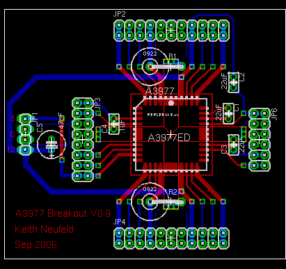
The biggest challenge in the layout was designing adequate heatsinking. The A3977 doesn’t have a solder pad on its belly, and I’d have had a hard time soldering it even if it did. Instead, the three pins at the center of each edge are ground pins that double as heatsinks, and they want a big copper area for dissipating heat.
I used EAGLE’s polygon feature (I think that’s what it was called; I should have taken better notes while I was doing this) to make big copper areas. In the above picture, the brighter red and blue outlines show areas that will be filled with copper on their respective sides of the board.
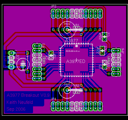
Hitting the ratsnest button then flood-fills copper into not only those areas, but the rest of the board, leaving a specified gap between the copper ground plane and any pins not specifically identified for inclusion. Since I was planning to etch the board in the sink, leaving large copper areas not only provides the requisite heatsinking, but saves on etchant and etching time.
Building the Board
Immediately after making the board, I got the A3977 soldered onto it. Because the board was hand-etched, it was a lot dirtier than professionally-manufactured boards, and soldering the big PLCC chip onto it was correspondingly more difficult. But I got all good joints and no bridges, as confirmed with the continuity tester.
And then the board sat from September through April. Sigh.
A Kick in the Seat
A few weeks ago, I suggested to John Harrison that we needed to get back into having a “geek club” meeting every Monday night this summer–and that at every meeting, every member had to show or demo significant progress on some project. It’s amazing how much you can get done when you have peer expectations of continuous achievement.
I called John on Friday evening and told him that I needed a pep talk: I had a wide open weekend and two electronics projects that I could work on but was reluctant (and/or intimidated) to start. I could finish the work and blog on repurposing a battery-operated motion sensor (coming soon) for class, or work on my stepper controller.
He asked which one I was going to show him on Monday night. Well!
That was the motivation I needed, even though it turned out he’s out of town Monday. By the time I went to bed Friday night, I had the whole board assembled (except for the pieces I forgot). Instead the motor running, though, it kind of twitched and buzzed.
I reread the datasheets and applications notes as I was going to bed, and realized I had somehow left out the RC components for the output waveform generators. My wife woke me up at 6:30 Saturday morning for help with the laser printer before running off to manage the local food coop’s distribution day, and by the time normal people were up, I had the controller running the motor at full speed.
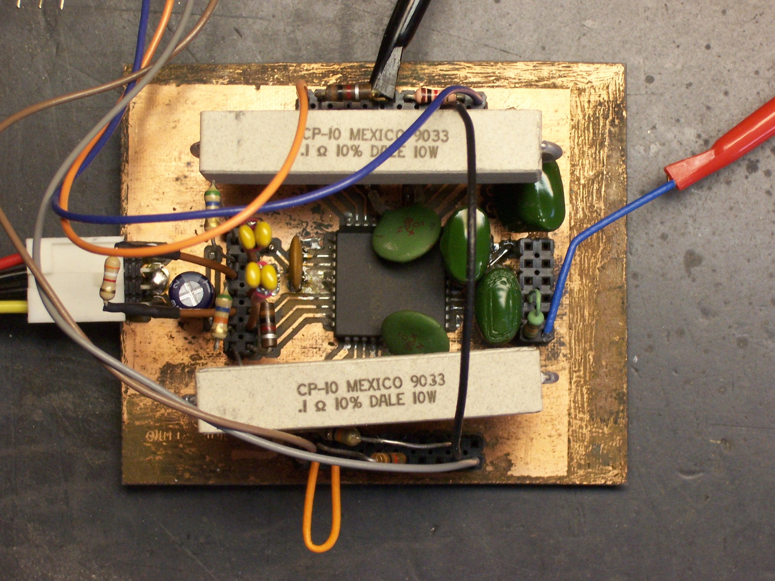
Here’s what the board looks like with everything installed. The big sand resistors are the sense resistors–and yes, that is .1Ω (although I tried .2Ω first and will probably go back to it). The weird green things are capacitors for an internal voltage boost circuit. The motor coils are fed from the orange, blue, brown, and grey wires that take off from the upper and lower corners. Power from a PC power supply comes in the left, and the red probe and blue wire on the right provide a step signal from my function generator so I can test without hooking up a microcontroller. The extra wires and resistors around the outside are jumpering things like /RESET, /ENABLE, and DIR, again to facilitate μcontless testing.
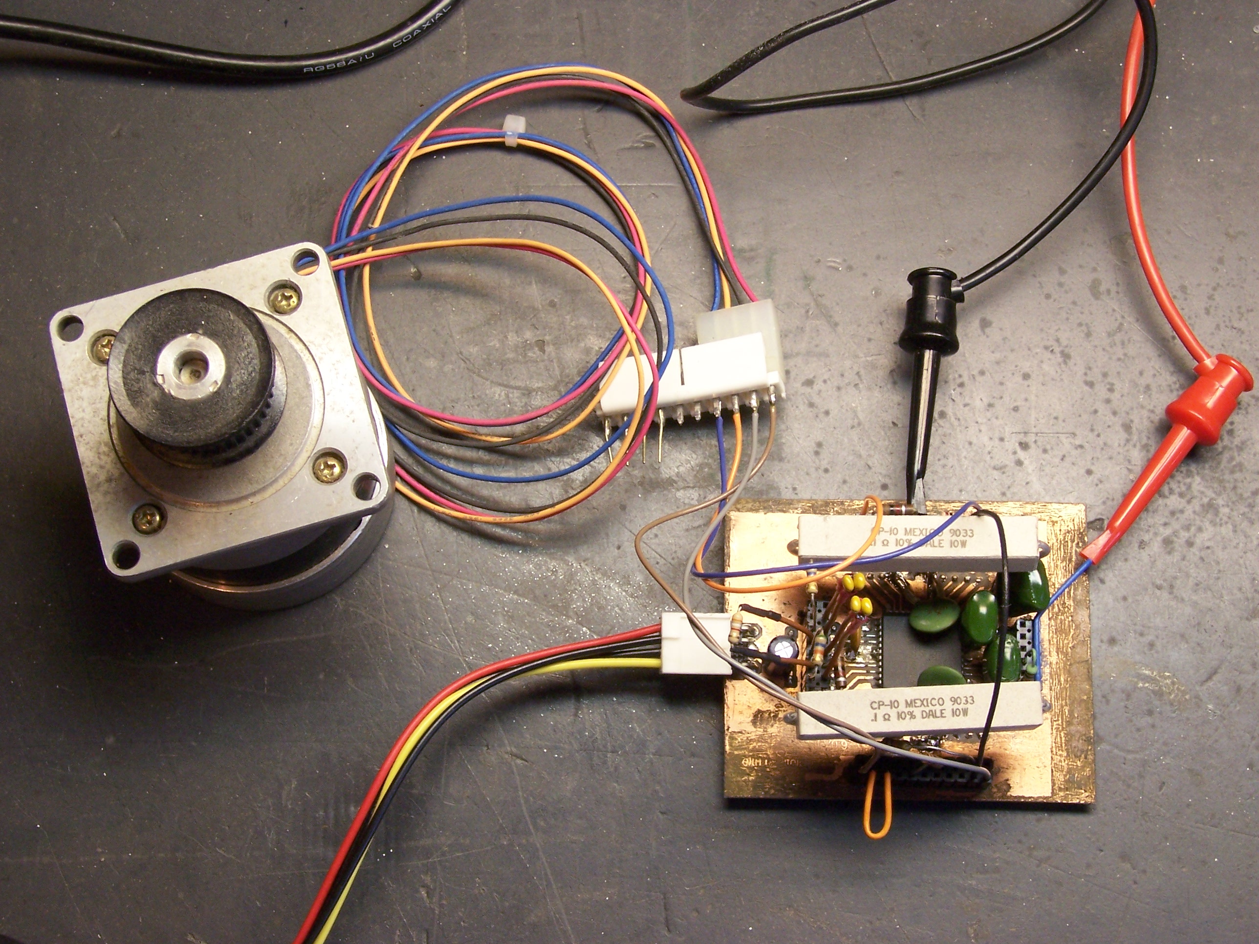
Thar’s what it looks like with the motor.
How It Works and Lessons Learned
Speed
I was surprised that I wasn’t able to get it to run faster than it does. I haven’t measured exactly, but I guesstimated I was hitting about 600 steps per second (3 revolutions per second) before it started jittering instead of turning. I tried half- and quarter-stepping (at correspondingly higher clock rates), hoping the smoother drive would increase the maximum rotation speed, but it didn’t. I swapped out the sense resistors to increase the motor current, but that didn’t increase the maximum speed either. I could tinker with the ramp generator’s RC values, but I don’t think that’ll help either. The controller is rated for 600,000 steps per second (!!!), so I’m pretty sure the limitation here is the motor, and I’m just pushing it as fast as it can go.
That’s a little disappointing, because (1) that’s only a little faster than the 500 steps/second I was getting with my MOSFET driver; and more to the point, (2) with a 20 thread per inch lead screw, 3 revolutions per second works out to about seven seconds per inch of travel. That is, if the cutter head is at the opposite side of a sheet of typing paper and needs to come back, it’ll take a minute for it to travel across. That’s pretty painful.
The documentation at the LinuxCNC (née EMC) web site suggests that high-speed CNC machines use DC motors with optical encoders, rather than steppers. I guess I’ll look into that for version n + 1.
Advantages?
I’d been hoping that the current-control system would be the silver bullet that pumped this motor up to dramatically higher speeds. Since that’s clearly not the case, is it still worth using this chip over the discrete MOSFET design I made?
I say yes. The A3977 is much smaller than the eight TO-220 FETs (plus heatsinks) required in the discrete transistor design.
The A3977 also runs a lot cooler. Its temperature rose to the mid 90°F range after several minutes of continuous full-speed operation. In contrast, the FETs got hot enough to burn fingers (I didn’t have my infrared thermometer yet) after only a few seconds of operation.
Allegro would claim that the A3977 also improves the pin count for processor interfacing–it requires only two pins (direction and step), whereas the discrete transistor solution requires four pins (two wires each for two coils). This is probably valid, although the plethora of options (half-, quad-, and eighth- stepping, reset, etc.) will tempt me to use up those saved pins controlling other facets of the stepper operation.
Sense Resistors
I had ordered big sand resistors with thoughts of stacking them to kill voltage in my MOSFET design. But defining ITRIPMAX as the maximum instantaneous current of each output ramp cycle (in my case somewhere between 2.5A and 5A), the A3977 recommends:
VREF = 4V
RSENSE = VREF / (8 * ITRIPMAX)
= 4V / (8 * 2.5) = .2Ω
Which is what I’m using. BUT working back:
V = I * R
VR = 2.5A * .2Ω = .5VP = V * I
P = .5V * 2.5A = 1.25W
So the resistors need to be large, but not quite so monstrously huge. (These are 10W.) I’ll shop for smaller ones before building the real board.
Hey Keith – I’m working on an A3977 (actually A3979) board design too, just in the schematic-drawing stage.
I noticed you’re using Dale wirewound/ceramic resistors for the sense resistors. I believe these aren’t suitable due to their inductance. Most people seem to use Ohmite non-inductive current sense resistors, 13FR200E, or else Vishay NS01A. At the moment I’m planning to go the cheap route and use 5x 1-ohm 1% metal film resistors in parallel.
The other thing is that the maximum speed of the motor is directly related to the supply voltage. Using 24-30 volts will get you going a lot faster than the 12v supply you’re using. After that, tweaking the R/C values for your particular motor may also improve things.
All this I only know from reading data sheets and forums, so take it with a grain of salt…
By the way, my task at the moment is to figure out how to protect the chip from voltage generated by turning the motor by hand, when the chip is disabled. I’ve heard people say this can easily fry the chip. Ever heard anything about that?
Good luck with the project…
Hello,Keith,would you please mail the tipical applicition of A3977 circuit diagram to me? i need your help.Thanks a lot.
my e-mail,****************@sina.com.
Nora, here are several working A3977 boards available online that I found via Google:
http://www.thsengineering.com/projects/a3977proto/a3977proto.html
http://www.students.tut.fi/~kontkant/a3977.php.html
http://pminmo.com/ss3977/ss3977.htm
My board design is still in the prototyping phase and not finished yet, so I don’t think it would be useful to you.
Hello, I am working in a board prototype for motor control and I need
some help. In my development, I am using a3977klpt controller and i am
having some problems. when I test the board connected to a motor , this
motor only works in a one direction. if the DIR pin is logic low and
step pin set by pc, this circuit works fine, but if the DIR pin is logic
high (5VDC, the same as VDD controller), the motor not works in other
direction, it is bloked.
Can you help me?
Boris, this may sound silly, but double-check that you have a good logic ground connection between the A3977 board and whatever is feeding signals into it. That really sounds like a floating ground problem.
If that’s not it, tell me more about how fast you’re trying to step the motor and exactly what happens when you try to go the other direction. Does it move at all, jitter back and forth, growl? Can you turn the motor shaft freely by hand, or is it held stationary?
Hello Boris and also all,
I got the same problem with DIR on my test board. I tried to find an answer but nothing until now. I will try again this week and I hope I will not have the same problem with the new A3977 IC.
Boris! What happens if I reverse the polarity for a micro second of the pole I am leaving to get to the next pole of a stepper (bipolar stepper)?
What am I going to fry now?
If you respond, thanks
M. Timm, since the stepper’s coils are inductive loads, you’re going to get a huge current through your driver if you do that. That’s about as far as I can guess.
hello everyone,,,
i need a simple circuit for running a stepper motor clockwise and anticlockwise WITHOUT USING ANY OF THE PC PORTS…plzzzz help….
Hello rv,
Please tell us more info about this circuit what you need becase maybe you want variable speed or not, maybe you need a period to left and then right automatic….
1. Use a 555 circuit for step, you can find on internet 1000 of schematic and the a swich for direction….
2. You can use a pic microcontroler pig 12f509…. 16f84a.
(with pic 12f509 you need only one reset button and an resistor).
Sorry for my English.
I am planning to use “Allegro A3977″ in my robot. Do you know any website that has a good schematic of a complete stepper motor driver circuit? The one that you used, may I get the schematic for that? I will really appreciate it.