Archive for the ‘CNC’ Category

Rebuilding the CupCake Extruder Heater (When It Wasn’t Very Broken)

Sunday, January 29th, 2012

After some success back in June using fans to cool extruded layers on my CupCake — in fact, right after that success — it slowed extruding and eventually stopped extruding altogether. This is the story of my life with the CupCake — a very brief success from time to time, but never persistent nor replicable.

When I say stopped extruding, I mean the motor actually ground to a halt. Usually it chews a divot into the filament, but this time it stopped. And I was pretty sure — don’t remember whether I actually checked the on-screen display or not — that the nozzle temperature had dropped and the filament wasn’t melting any more.

I know people talk about extruding ABS at temperatures as low as 200°C, and I don’t find that to be the case in my CupCake. Mine is calibrated, and mine doesn’t like temperatures that it thinks are lower than 220°C, and mine doesn’t really like temperatures that it thinks are below 225°C. So it really doesn’t take much to make it unhappy.

Nichrome wire crimped to teflon-coated wire

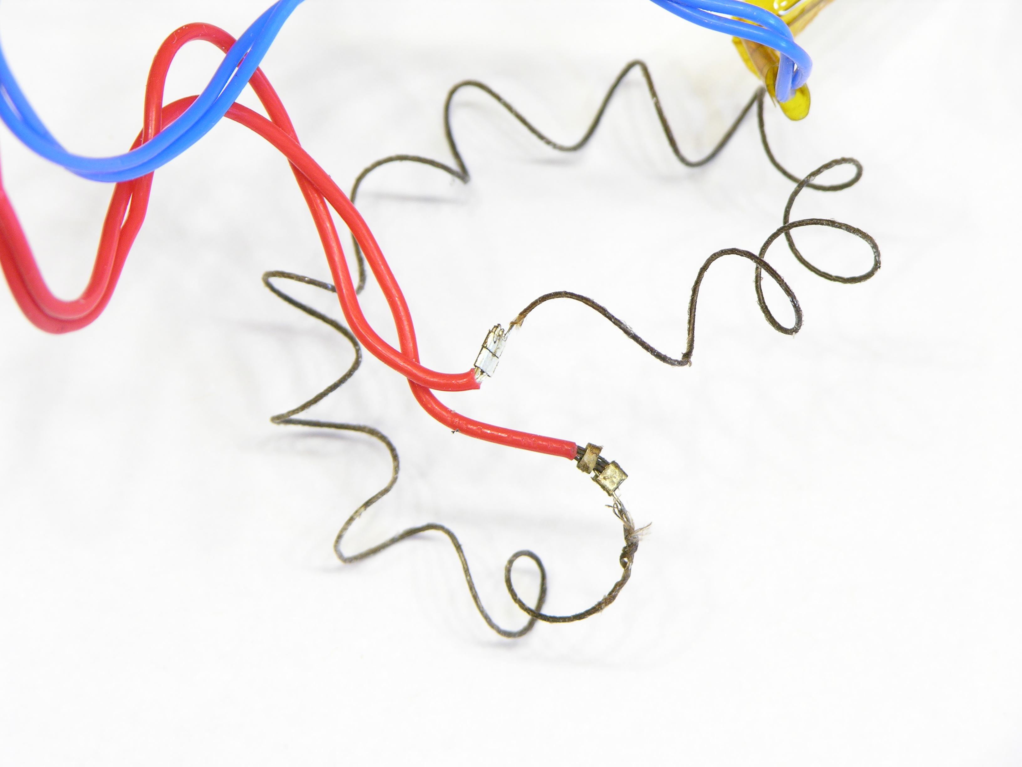
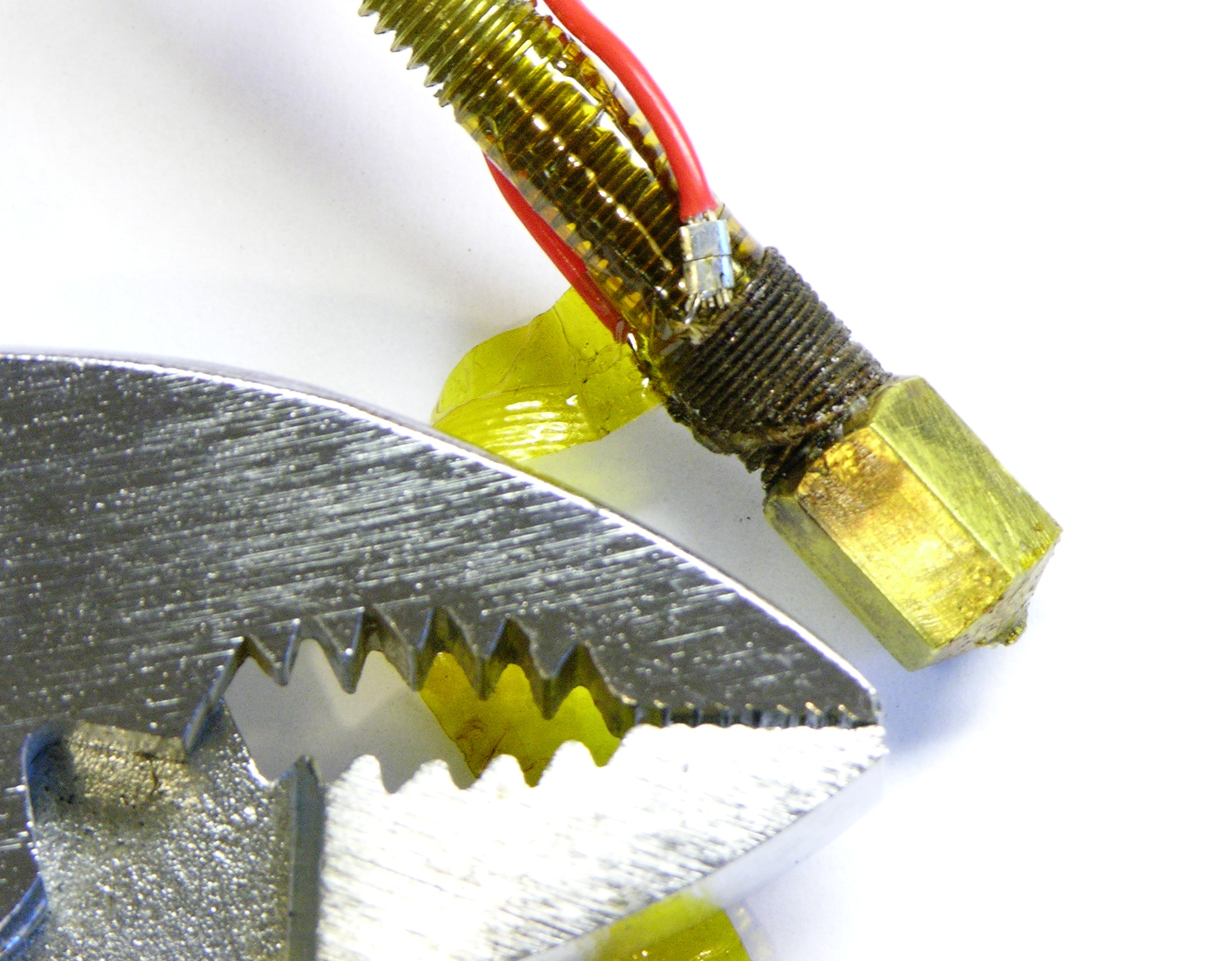
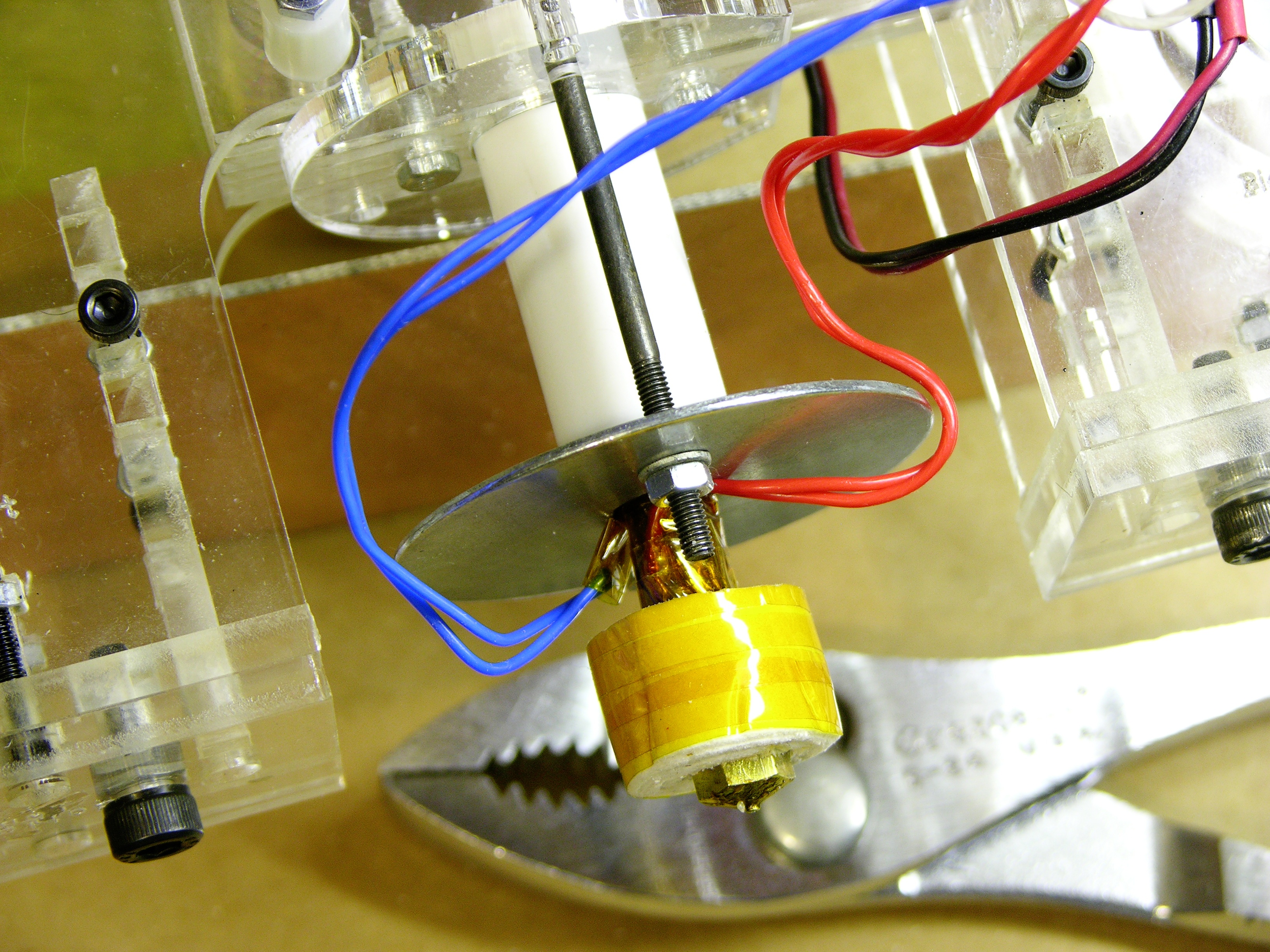
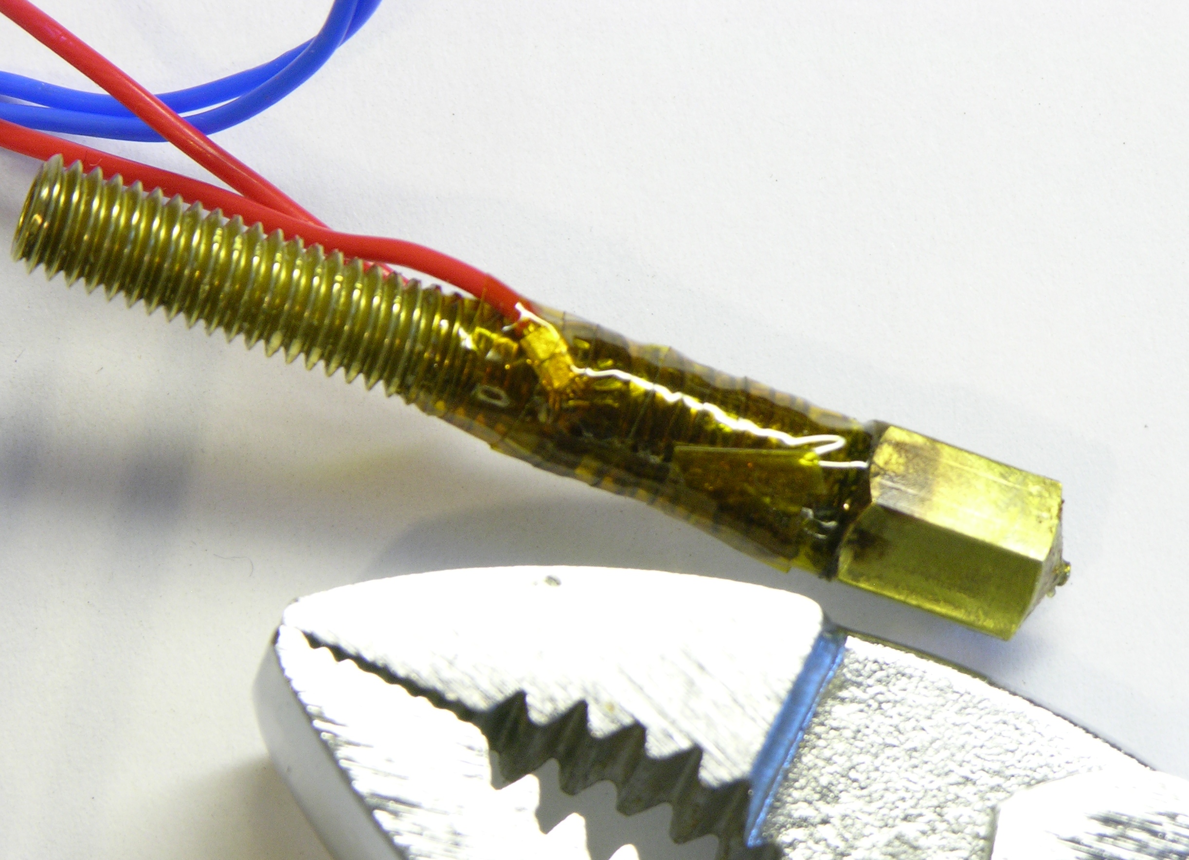
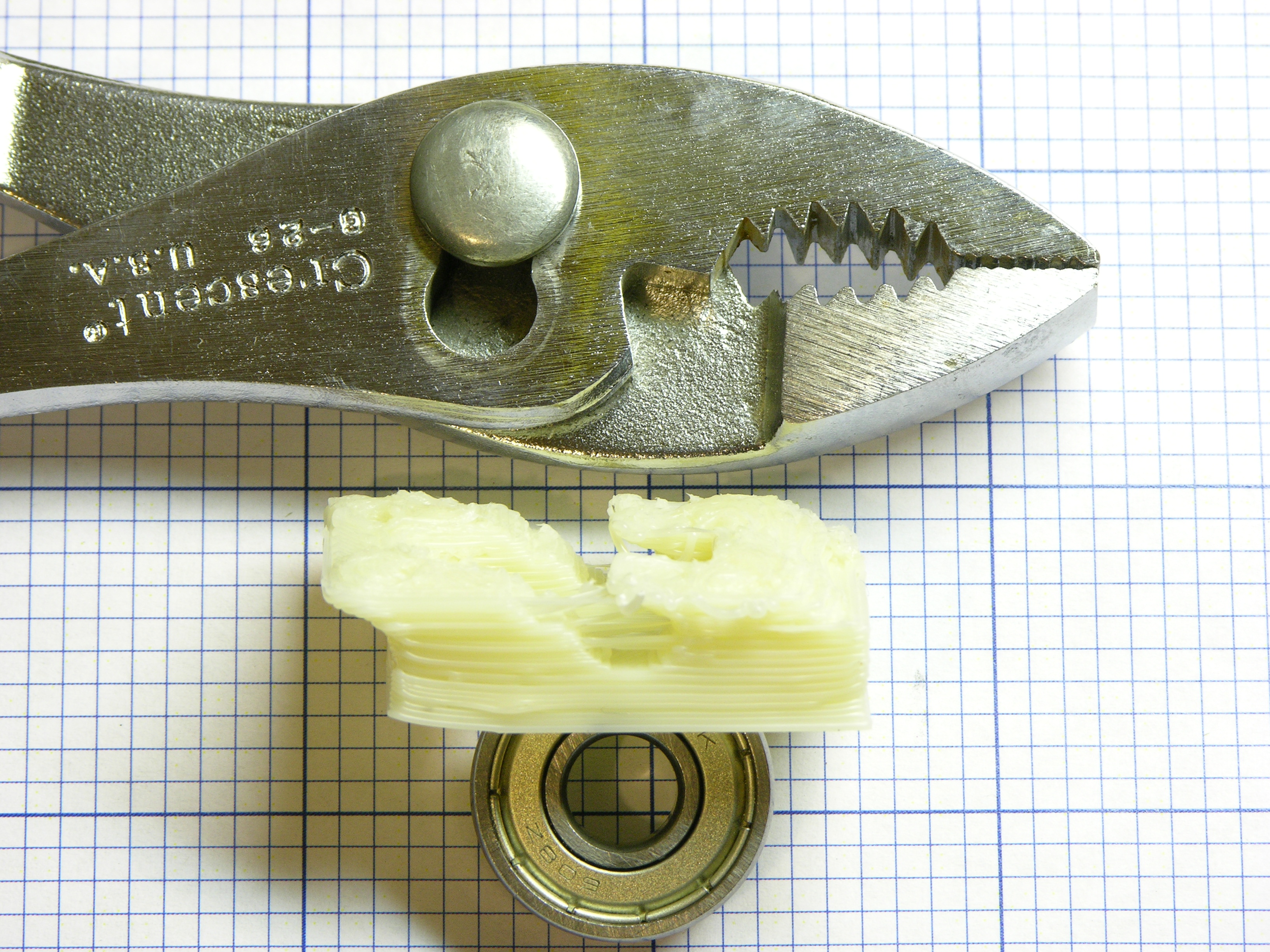
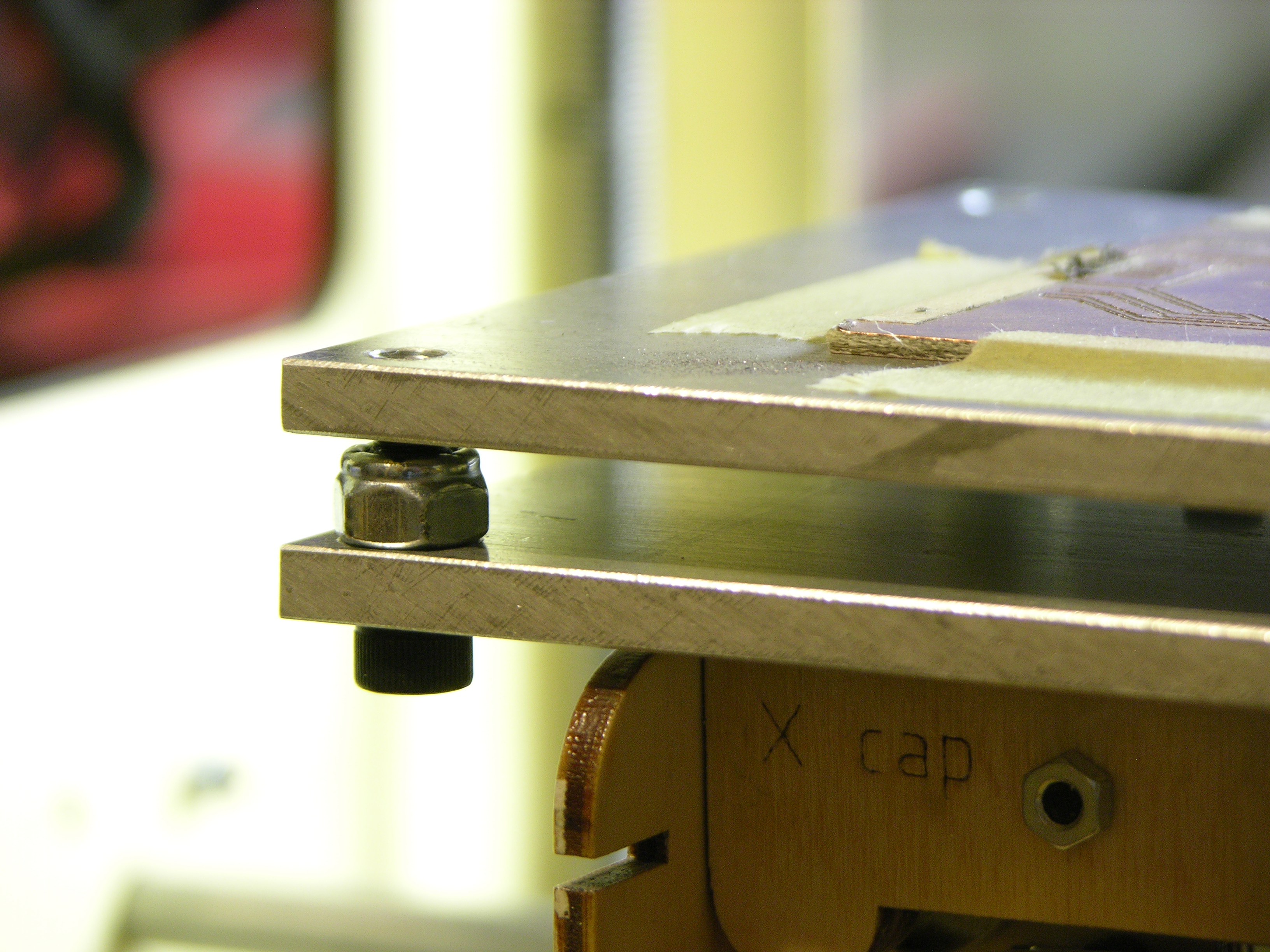
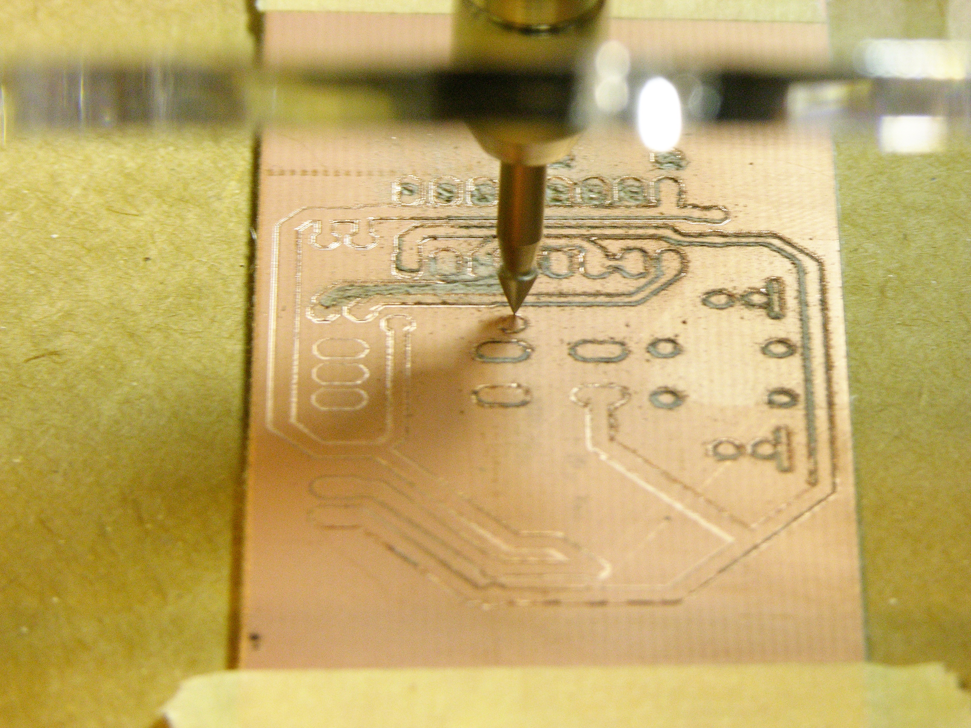
I had just rebuilt and rewound my heater at the time, and I knew that I had crimped the nichrome to the teflon-coated lead wires with silver crimp beads. I had a suspicion that the joints had become oxidized under the crimps, and the 7.3Ω resistance across my heater wires seemed high for my CupCake.

A couple of weeks ago I disassembled the heater and found that one of the two connections was indeed quite scorched and oxidized.

Nichrome wire crimped to teflon-coated wire

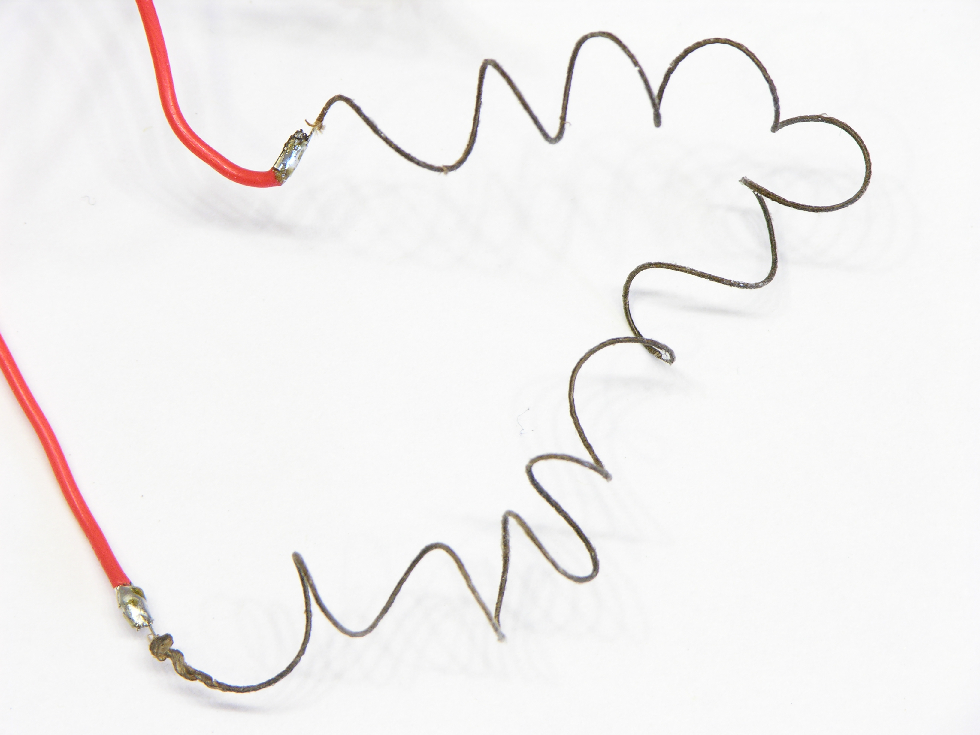
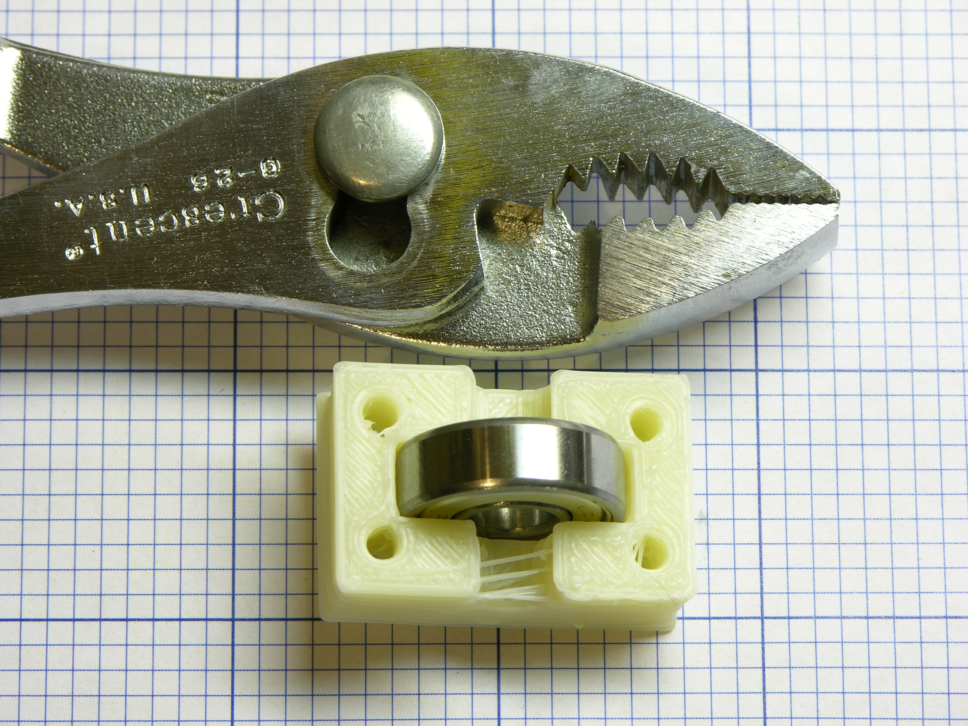
After cutting away the crimp tubes, cleaning the end of the nichrome wire with fine sandpaper, cutting back the lead wire, and recrimping, I tinned both lead wires with solder. Solder doesn’t stick to nichrome; but being coated with solder, the joint (which already had a solid mechanical connection from crimping) should be much less prone to oxidation.

After the rebuild, the heater measured 6.8Ω. Half an ohm difference doesn’t sound like that much until you’re trying to get to 225°C. Since power P = V2 / R, at 7.3Ω, P = (12V)2 / 7.3Ω ≈ 19.7W; and at 6.8Ω, P = (12V)2 / 6.8Ω ≈ 21.2W; so maybe that could be enough to make the difference at the high end of the extruder’s temperature range.

ReplicatorG control panel with temperature failing to reach set point

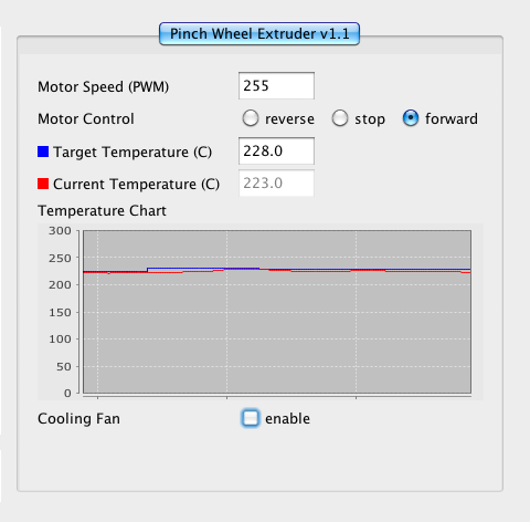
Aaaand … after reconnecting things, I still couldn’t get the temperature above 222-223°C, even though it now had some 7% more power. That doesn’t seem quite right.

Pulse-width-modulated heater signal on oscilloscope

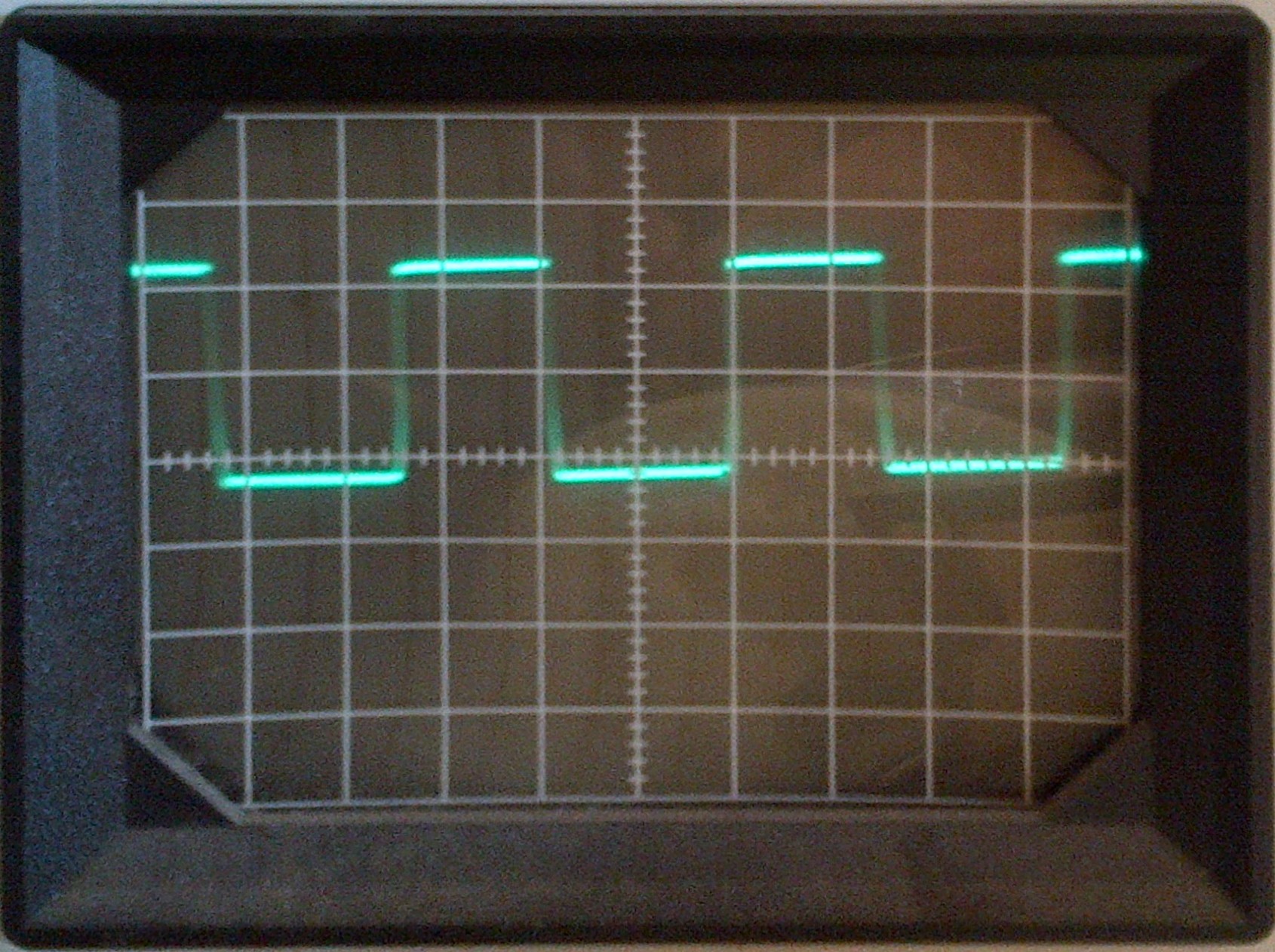
When in doubt, scope it out. Yeah, after almost a full minute of failing to hold the temperature at the set point, the software PWM in the extruder controller was still running the heater at about a 50% duty cycle. That definitely doesn’t seem quite right.

And isn’t something I can easily fix, either. The ReplicatorG version I was running didn’t have a control panel for the heater PID settings, so (even assuming I was smart enough to fiddle them into shape) I would have had to recompile the code each time I wanted to make a tweak, which wasn’t palatable.

Firmware Upgrade

But I thought I’d heard that newer ReplicatorG versions did bring the PID coefficients into the machine control panel, so I upgraded ReplicatorG from 0024 to 0029r2, and let it upgrade my firmware from v2.4 (I think) to v3.0, and lo! lost communication between ReplicatorG and the CupCake. It said it had a connection but all the menu options to talk to the CupCake were greyed out.

Great.

This is apparently a known problem claimed to have something to do with the Mac’s localization settings for the string representation of “,” and “.” in numbers. Srsly? And the suggested tweaks didn’t fix it for me, so I’ll just wait for the next ReplicatorG release. And since the Mac package of ReplicatorG continues to be a DMG file of all the pieces you have to drag into /Applications/ReplicatorG, rather than a ReplicatorG folder that one could conveniently drag into /Applications like everyone else provides … I guess I should feel lucky to have a Mac version at all, and I’m not holding my breath for a fix on this problem.

Anyway, downgrading ReplicatorG to 0026 restored my connectivity and got me a look at those sweet, sweet PID coefficients.

ReplicatorG heater temperature graph

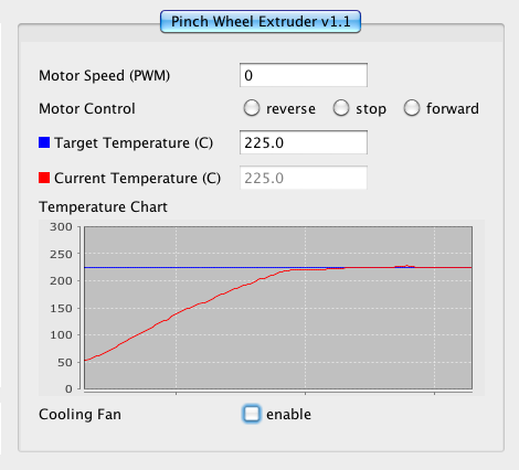
Which I no longer need, ’cause with the upgraded CupCake firmware, the PID algorithm seems to work right. Reaching for the knobs was obviously an attempt at a workaround, and the real fix is oh so much better.

Plastic-extruded filter holder assembly

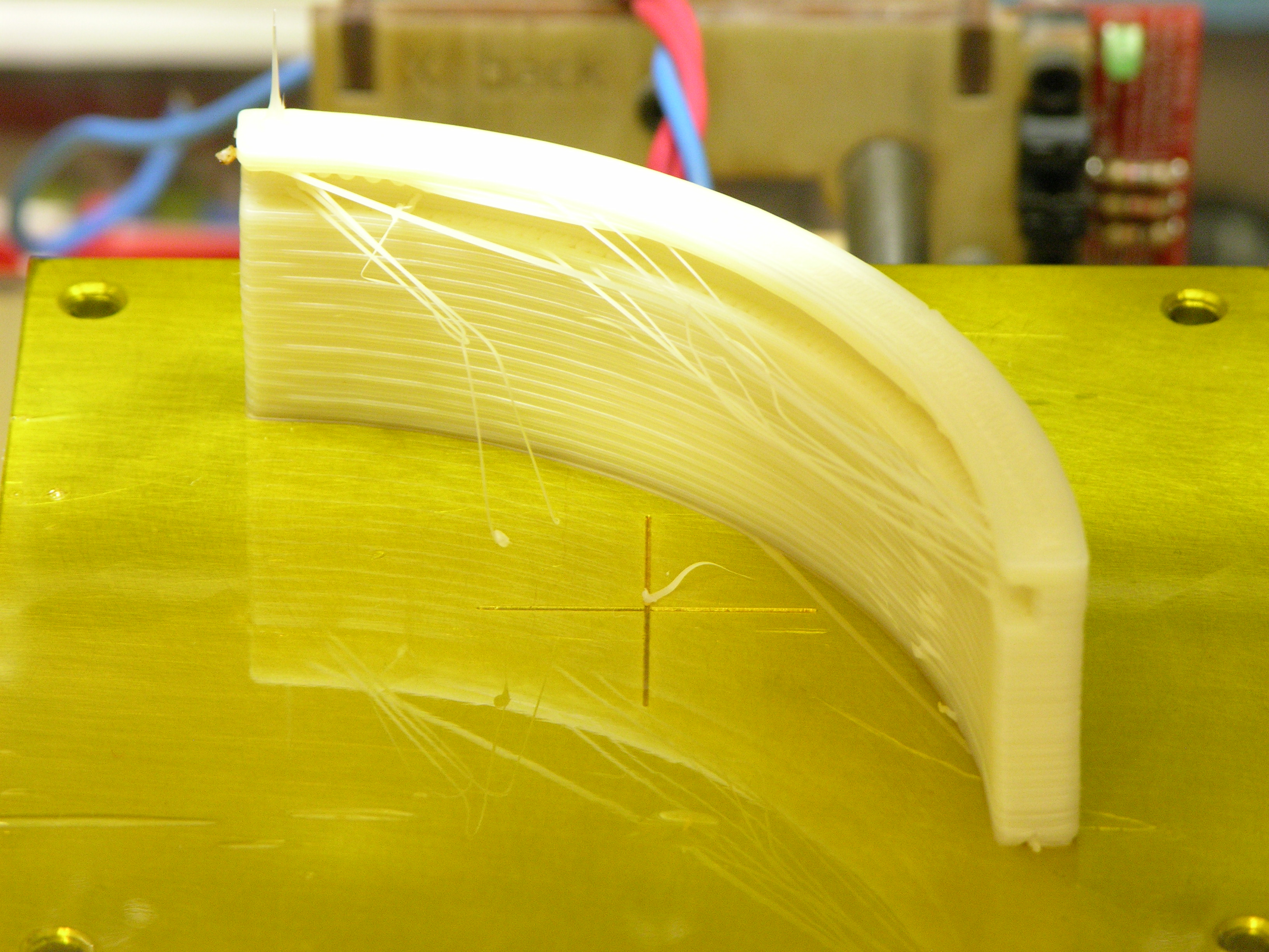
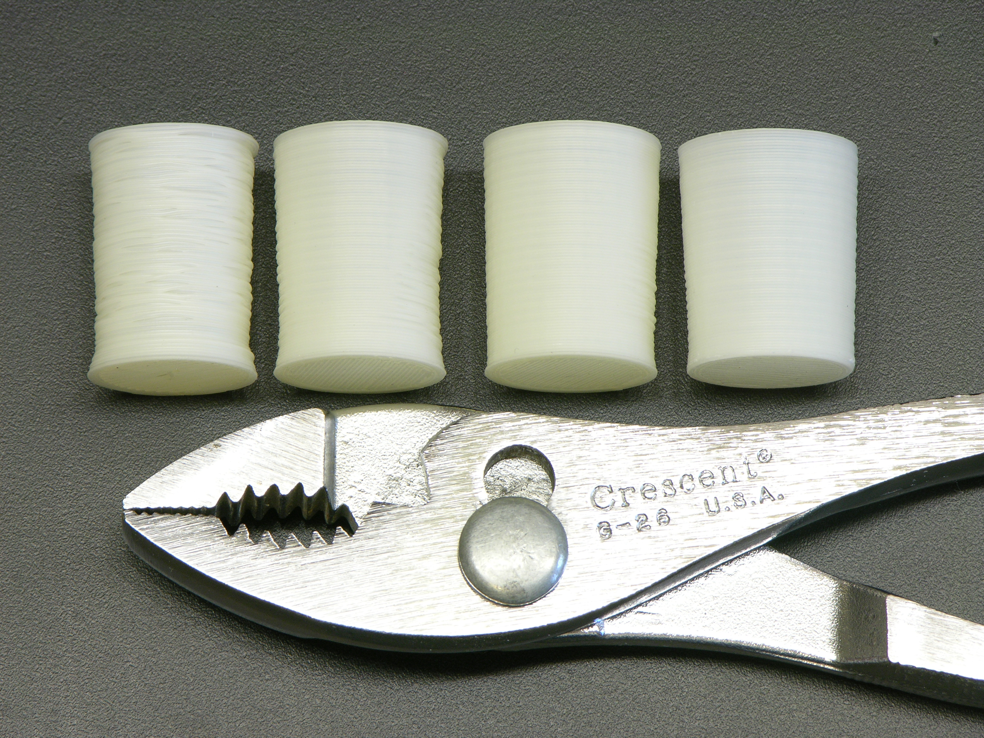
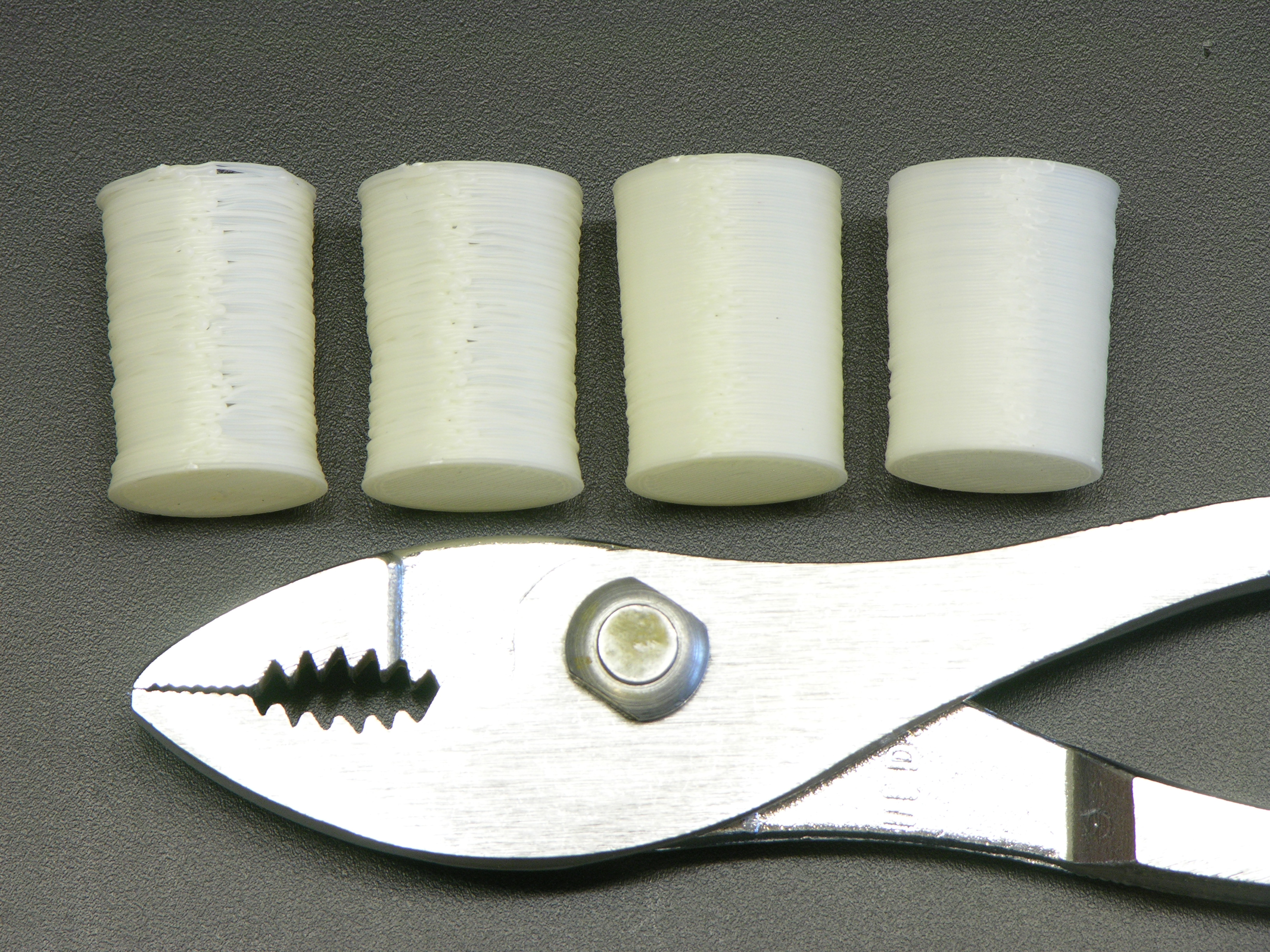
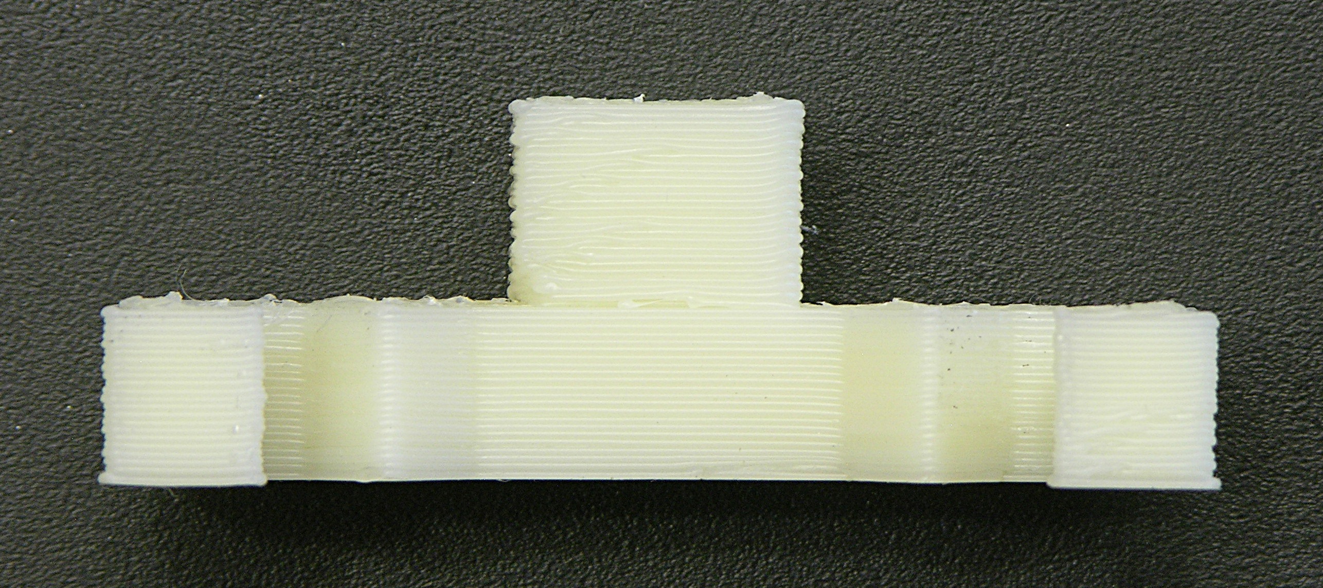
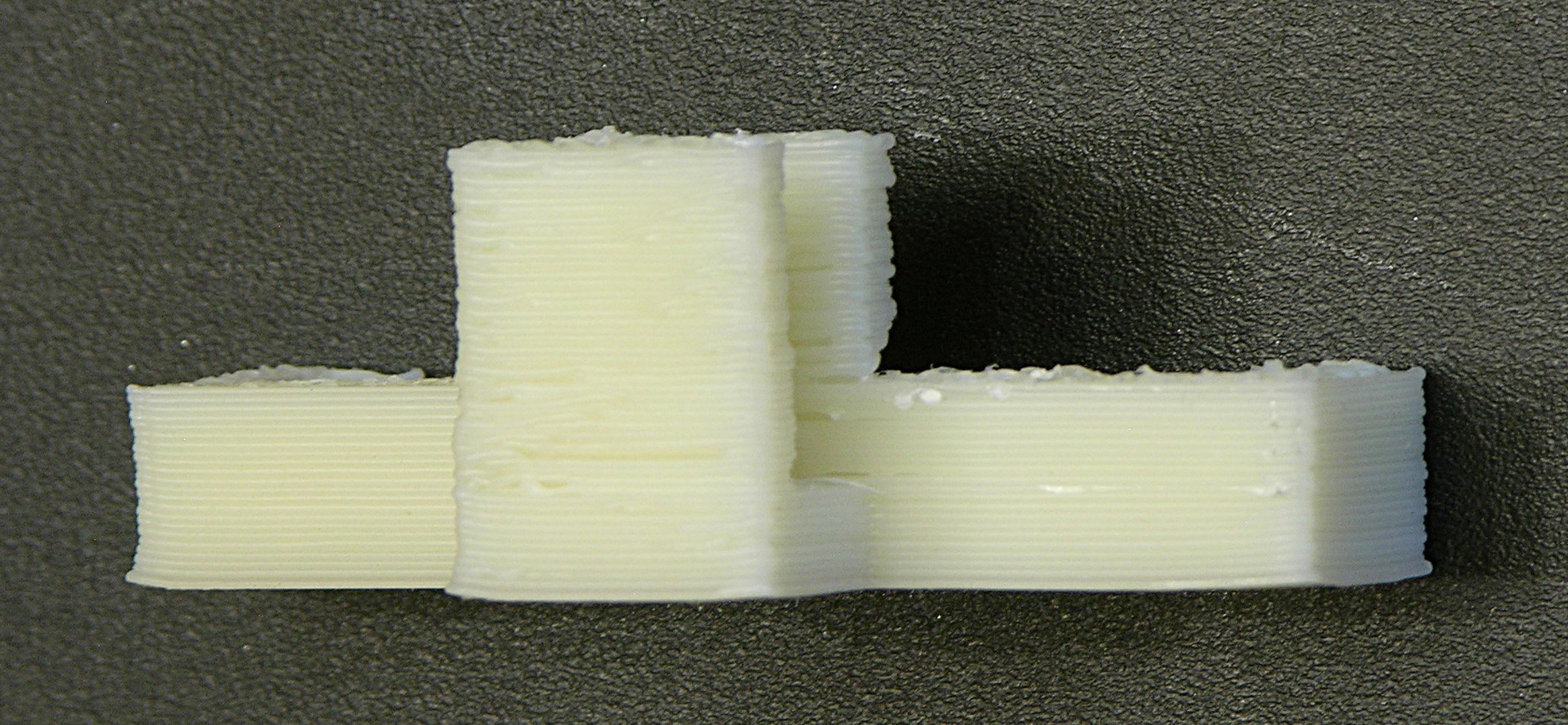
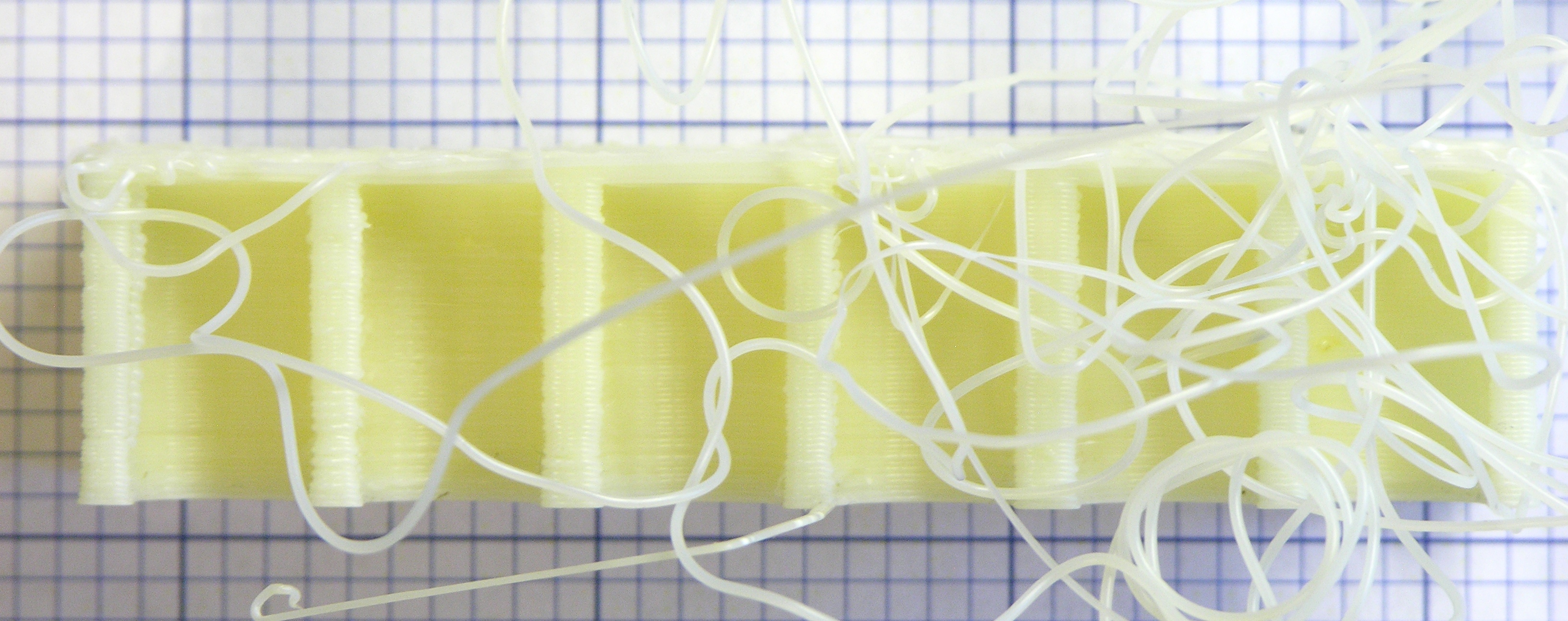
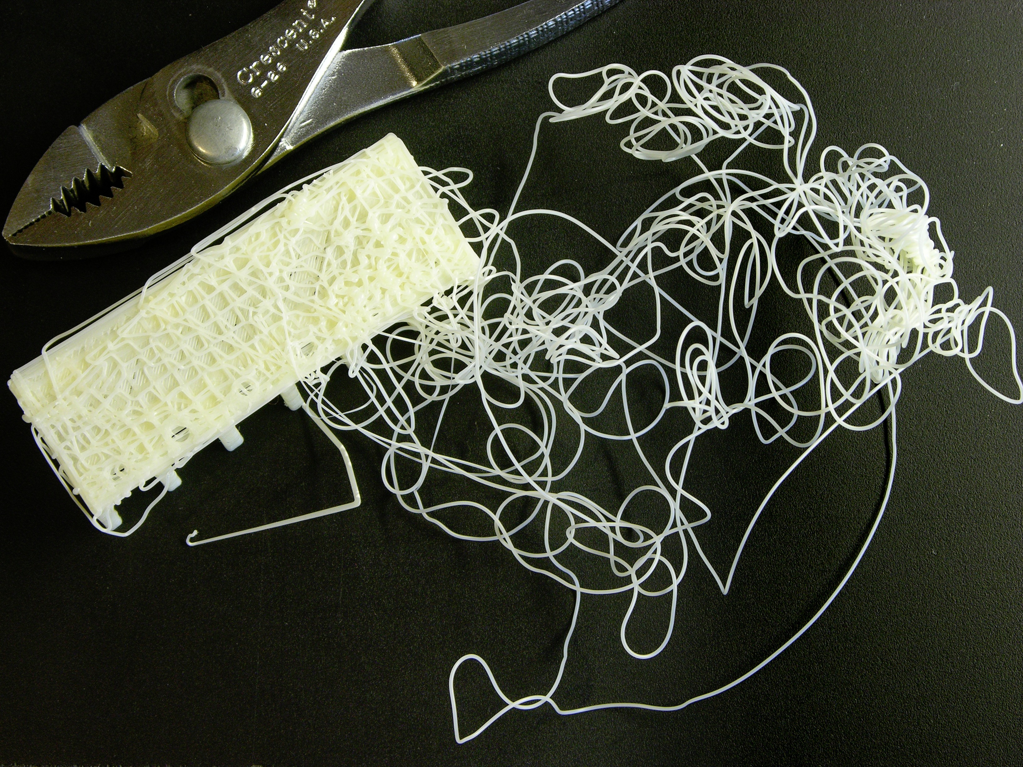
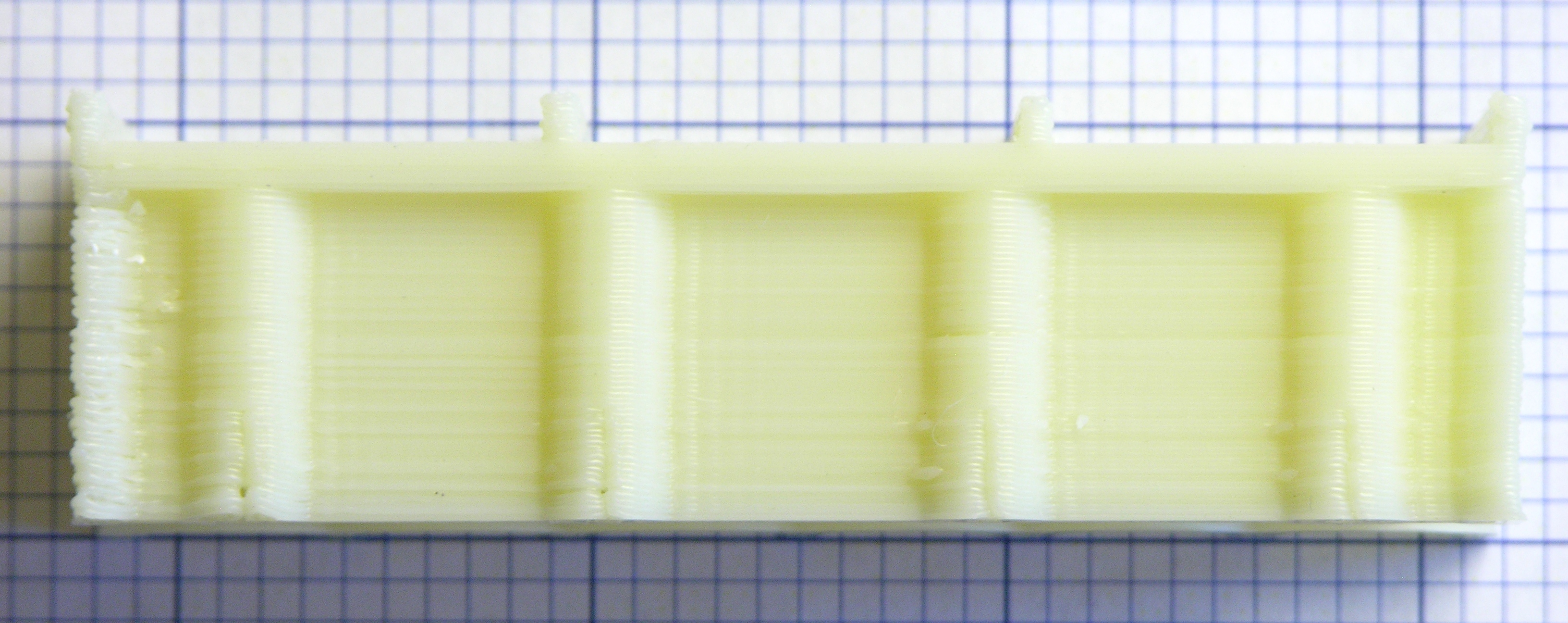
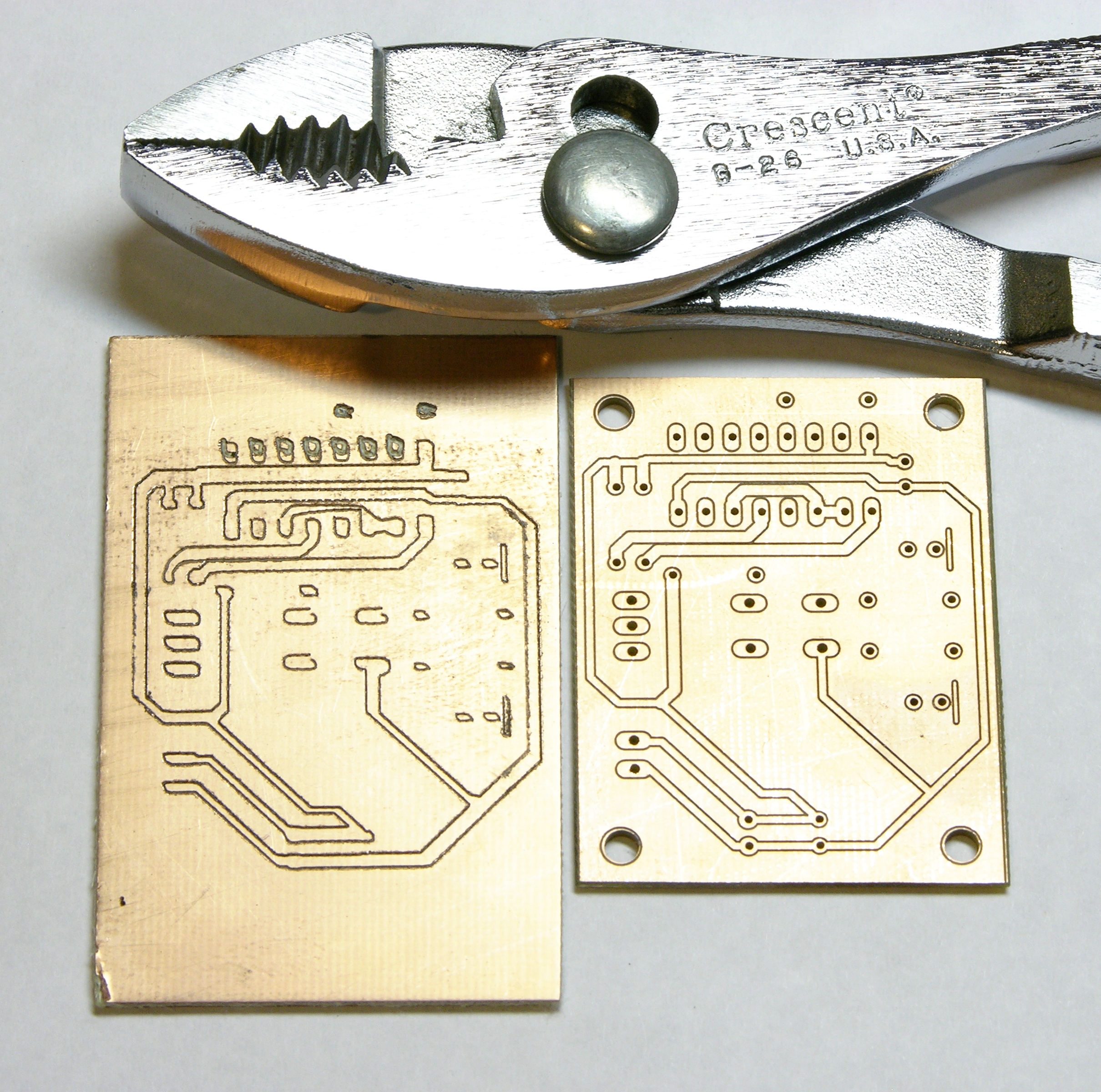
The stringing on this diffusing filter holder is my fault, not my machine’s — I have a 0° (or 90°) overhang on a concave curve, so there’s no way it was going to come out clean. I still wanted to see what it would do, and it performed admirably under the circumstances of an impossible model.

And then stopped working again.

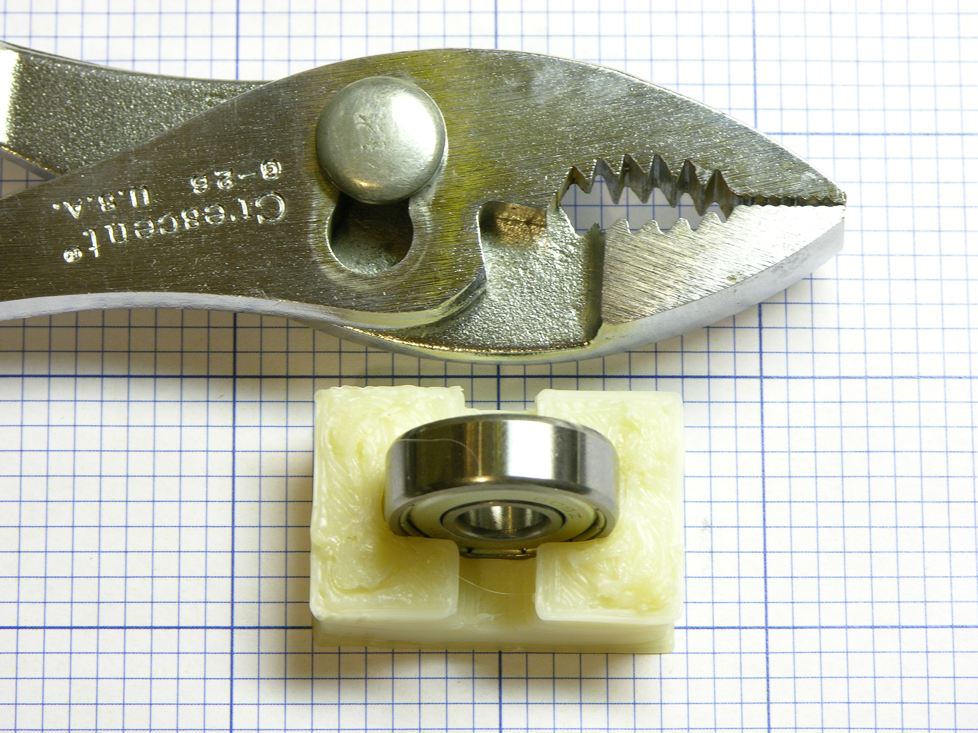
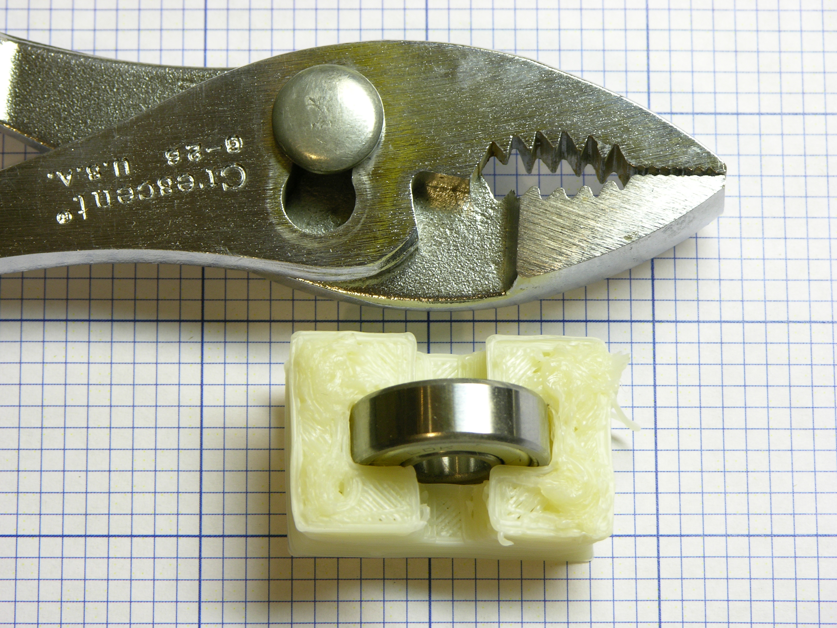
Filament drive motor locked up against the filament. A-gain. (Yay, great grip on the drive pulley, and nozzle retaining washer not breaking!) Temperature claims to be steady where set.

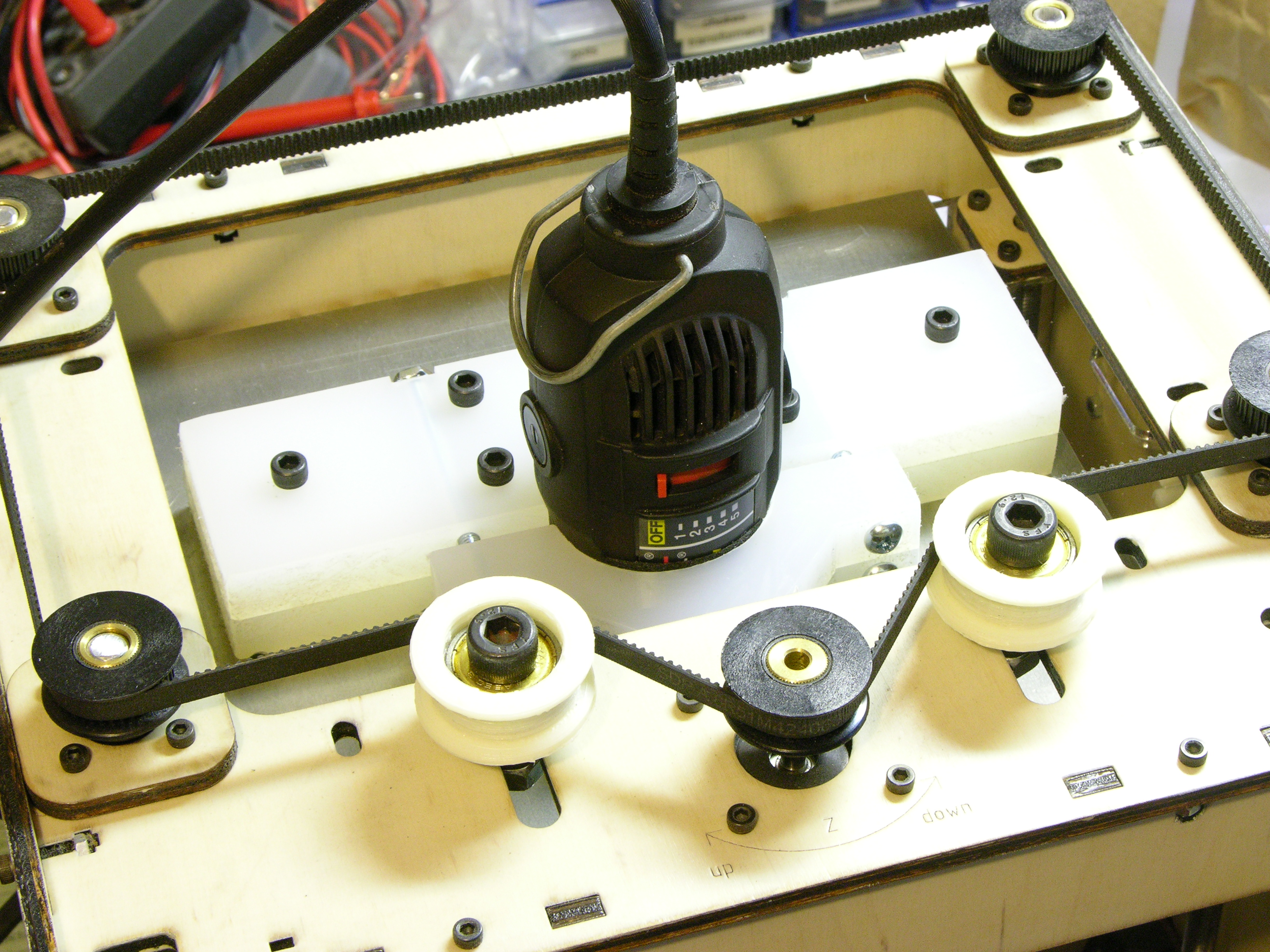
My utility is fairly cold these days. I’ll try enclosing the build chamber again in hopes that although the nozzle is hot enough, the teflon tube is too cold — but I bet I end up disassembling and drilling out the inside of the tube and nozzle again.

Should have been designed with a quick-release.

Cooling Fan(s) for Dramatic Improvement in CupCake Print Quality

Sunday, June 12th, 2011

While trying to print a replacement cap for a spray bottle (which I ultimately want to do in PLA, but that’s what broke my extruder and I’m working my way back up to it), sizing the cap properly for the bottle was complicated by the cap shrinking unevenly while the build was still in progress. I knew I needed to turn down the build platform temperature as soon as the first layer had adhered; but the cap was so thin that the platform didn’t lose heat fast enough to make much difference.

Spray bottle caps printed on MakerBot CupCake, front side

I connected a spare DC fan to my bench power supply, set it just outside the CupCake’s build chamber, and dialed it down until it barely spun. Holy schmoly! The left cap (you’ll need to click the image for the larger version), made with no cooling, looks like an art project woven out of twigs; the next one is extremely smooth on the side that was facing the fan — better than anything I’ve printed before!

Spray bottle caps printed on MakerBot CupCake, seam side

The “seam” was on the side away from the fan and doesn’t look so as great as the fan side — but if one fan is good, two are surely better, right?

Deposition cooling fan on MakerBot CupCake

I designed and printed clips to press-fit onto a couple of 1.6″ DC fans I had sitting around (the clip is good enough to use but I have some dimensional tweaking to do before posting on Thingiverse) and positioned them at opposite corners of the build chamber, blowing around opposite sides of the object on the build platform. (Hey, I’m from Kansas. Vortices come naturally to us. Go buy a Vornado.)

The third and fourth prints above are with two fans running, trying to find optimal airspeed to cool the deposited filament but not cool the nozzle so much that the ABS solidifies before exiting. (I filed down the seam on the fourth; it didn’t really print quite that well.) I think the ultimate combination may be an enclosed build chamber to raise the overall temperature and fans to cool the layer just printed.

Many CupCake, RepRap, and Hydraraptor operators have added cooling fans, but I don’t recall seeing dramatic before-and-after pictures. Based on what I’ve observed during mesmerizing hours of watching the CupCake print, it’s obvious why it helps — without active cooling, the previous layer is still molten enough that the soft extrusion being deposited by the nozzle still applies enough force to squish the previous layer out of the way in some random direction. It may have been deposited in the right place, but it’s not in the right place any more after the next layer moves it. With cooling, it stays put.

Z-Axis Wobble and Ooze

The CupCake carries the extruder up and down on a platform supported by four threaded rods. It’s a very economical design, but the rods are less precisely straight than Acme threaded rod and aren’t a perfect fit for the ID of the pulleys at the top. The combination of these factors results in the extruder platform swaying from side to side as it moves up and down. The effect is very visible during high-speed movement but still present during low-speed movement.

Spray bottle caps printed on MakerBot CupCake, closeup showing Z-axis wobble

My printed objects are finally at a high-enough quality that I can see the Z-axis wobble represented in the perimeter of the object. The faint ripples visible toward the left edge — about four and a half filaments high — match the thread pitch of the threaded Z-axis rods and are caused by the extruder circling through the X-Y plane as it raises during the print.

This effect is well-known and is a solved problem. Thingiverse user “twotimes” has designed a wobble arrestor that adds rigid, smooth rods to the Z axis and new bushings attached to the extruder stage to follow them in a perfect vertical motion. It’s time!

Cooling fan printed on MakerBot Cupcake, front-side closeup showing Z-axis wobble

The ripple is visible at the left end of the elevation view of this fan clip (and more obvious in person than in the photograph), but it is other imperfections that catch my eye. From the front, the bottom section looks very good, but the tower at the top (which once installed is the lower part of the extruder stage clip) has considerably more variation in filament position.

Cooling fan printed on MakerBot Cupcake, back-side closeup showing blobbing after non-contiguous perimeter

From the back, note the relatively high quality up to the top of the rearward extension for the clip — until which point the entire object has a single, contiguous perimeter. Above that level, the quality of the rear tower is much worse and the wall facing it is somewhat worse than below. The quality of the forward tower drops precipitously after the top of the main clip body.

Some of this may be due to the smaller cross-section leaving less time for the fan to cool the filament, but I place most of the responsibility on the filament drive in my extruder. It’s still the DC gearmotor design; the geartrain has a lot of backlash; and it’s not good at fast reversals. I’m optimistic that a stepper design will control the oozing, already improving the print quality, as well as making it practical to enable Skeinforge’s Cool plugin to pause printing between layers while the fan cools the just-extruded filament.

Another CupCake Nozzle Jam, PTFE Thermal Barrier Swarf, Heater Winding, and Glass Transition

Sunday, June 12th, 2011

I had written about jamming my CupCake nozzle trying to extrude PLA and having to disassemble the whole nozzle to clean and rebuild it. I got new PTFE thermal barriers (the white Teflon® tube) from MakerBot, put things back together, and quickly jammed the heater with ABS, which I’d never done before.

MakerBot CupCake Plastruder MK3 heater barrel with ABS leaked around barrel/barrier junction

I conversed with Nop Head about the increased force required to push filament through the heater and he pointed me to the junction between the brass heater barrel and PTFE thermal barrier. It needs to be absolutely closed, and when reassembling I’d left a tiny gap into which the ABS expanded (covering the end of the brass in the photo), interfering with smooth flow of more ABS into the brass. He gave me this video link to a vivid demonstration of the phenomenon, in which he is attempting to push filament into a heater assembly that’s wide open at both ends:

He gave me the tip to reassemble the brass heater and PTFE barrier with a drill bit of the nominal hole diameter inserted. When the two are turned together as tightly as they should be, the PTFE will begin to deform and just barely begin to grip the drill bit.

Believing the filament hole through the PTFE is metric and not owning metric drill bits, I figured the next best thing would be to use filament itself (which would be slightly undersized; but I could tighten until friction increased and then back off slightly). To my surprise, I couldn’t push filament through just the PTFE tube by itself.

Upon inspection, I discovered swarf where the little filament hole from the top meets the larger heater hole from the bottom, and this swarf was interfering so much with the motion of the filament that even after forcing the filament end past it, I still had difficulty moving the ABS filament through the tube. No wonder the heater was jamming!

I reached into the large end of the hole with a rat-tail file and used its tip to push the swarf into the small hole, then filed it free by push-filing upwards into the hole. After cleaning the PTFE thoroughly, I reassembled the heater and fired it up again.

In the past, I’ve been able to hear my stock DC gearmotor slog down when the filament reaches a certain point inside the heater, and I’ve always assumed that was due to the constriction of the nozzle. Not so, as my motor no longer slogs, and instead merrily pushes filament through like chocolate sauce dribbling out of the corner of a topping pouch! I have to assume that my original PTFE barrier had the same problem (to a lesser extent) all along, and I wonder how many others out there do too.

Thermal Gradient and Glass Transition Phase

While rebuilding the heater, I initially thought that part of my original problem must have been the top of the brass getting hot enough to melt the plastic filament that close to the PTFE, as I had always pictured the filament melting somewhere inside the brass. I’ve also read about hot-end designs with a heater near the tip and a heatsink higher up to keep the feed area cool and the plastic solid while inside it.

MakerBot CupCake Plastruder MK3 heater with nichrome wound near tip (doesn't work well)

I thus rewound all of the nichrome near the nozzle end and thermally insulated only the tip, thinking the cooler area above would help keep the filament from melting within the PTFE.

MakerBot CupCake Plastruder MK3 heater insulated only at tip

Even though after deswarfing the PTFE, the extruder initially worked far better than it had before, it proved not to be as reliable as desired, and I did notice the filament feed beginning to bog down. I had an ongoing email conversation with Nop Head, and he gave me this fantastic explanation of the hot end, which I reprint here with his blessing:

Most of the temperature is dropped across the PTFE and the point where the plastic melts (when stationary) will be about half way between the end of the barrel and the top of the insulator. This is where it is most viscous, so it is is good that it is inside something very slippery.

Brass is about 1000 times more thermally conductive that PTFE, but the barrel has a much smaller cross sectional area, so the thermal resistances are not as far apart as that, but still considerably different.

When the filament is moving the melt point will be much closer to the top of the brass due to the time it takes to melt because ABS is also a very poor conductor of heat and has a high specific heat capacity.

It’s a shame PTFE is not transparent, as it would be a lot more obvious when things were not working.

I think when at rest the filament melts in the PTFE. When moving I think it only gets above the glass transition, so when there is a gap it expands into it and jams.

Well, heck! If that’s the way it works, it sounds like I want the brass heated evenly (at least in this Plastruder MK3 design) to keep the filament as soft as possible at the brass-PTFE junction.

MakerBot CupCake Plastruder MK3 heater barrel with nichrome wound around entire length

I disassembled the heater yet again, this time rewinding the nichrome as evenly along the length of the barrel as possible and once again insulating the whole barrel. After reassembling, I haven’t noticed the feed motor bogging down as it was before.

Stratasys ABS Rapid-Prototyping Machine

Monday, May 30th, 2011

Another heretofore unfinished old post, this one from January 2010:

I was over at the aviation department last week and happened upon the installation of a new Stratasys rapid-prototyping machine.

Stratasys ABS rapid-prototyping machine, front left view

It has a much larger build chamber than NIAR’s previous ABS machine — this one is something like 14″ x 14″ x 18″.

Stratasys ABS rapid-prototyping machine, left side open

The case was open and I was intrigued by the thick blanket of insulation around the build chamber. I asked the installer if the whole chamber was heated and he said yes, to 80°C. Interesting point of reference, as RepRap / CupCake owners seem to have settled on 60°C as the standard temperature for heated build platforms.

Stratasys ABS rapid-prototyping machine, hazy shot of extrusion head

It was fairly dark inside the build chamber and I couldn’t get a great shot with my cell phone camera, but you can see the extrusion head with two nozzles for support and build material. I found it interesting how extremely broad and shallow the white nozzle cones are — maybe it helps prevent snags?

Filament from Stratasys rapid-prototyping machine

With the lab manager’s blessing, I fished two filament strands out of the trash. The upper, black filament is ABS; the lower, translucent brown filament is a dissolvable support material that apparently washes out in an agitated hot water and detergent bath. Wish I knew exactly what it was!

I measure the diameter at .070″ ± .001″ ≈ 1.778mm ≈ 1.75mm ≈ .069″, so it looks like they’re using 1.75mm filament. The stretched section on the end is recognizable as having been in the hot end and then backed out.

Note the toothmarks all the length of each filament (about 3m), suggesting that either something is pushing the filament from that far back or (more likely) the hot end has a quick-release for cleaning and this filament was run through the machine after removing the hot end.

CupCake Wants the Build Platform Temperature Turned Down After the First Layer

Monday, May 9th, 2011

I had previously noted the shrinking of the first few layers of a build on my CupCake and attributed it to the ABS shrinking too rapidly after extrusion because the room and the build chamber weren’t terribly warm. Although I’d leaned things against all of the CupCake’s windows so the heated build platform warmed the whole chamber, I thought that too much heat was leaking out when I prepped the print and removed the pre-print test extrusion and that it took a number of layers to heat the interior back up to non-shrinking temperature.

Large Kelly forceps with locking mechanism removed

I figured I could retain more heat inside if I didn’t have to move the front “curtain” to remove the test extrusion, so I went to The Yard and picked up a big pair of Kelly forceps. Since I wanted to use them as giant tweezers, I Dremeled off the locking mechanism, leaving myself with a big pair of plain ol’ forceps.

Mounting bracket built on MakerBot CupCake with lower layers warped

I heated the build platform and the now-more-enclosed chamber for half an hour (longer than the time it takes to print past the warped area), then sneaked the forceps in and snaked out the test extrusion. Whaddya know — the build warped in just the same way as before.

Hm.

I don’t yet have my build platform’s thermistor connected, so I’ve been running the heater open-loop using a lab power supply to adjust the temperature via current regulation. I remembered a while back when I had it so hot that the bottom half inch of my objects stayed melty-squishy while being built … and although I no longer run it that hot, I’ve been sloppy lately about turning down the current once the first layer is adhered to the platform.

Mounting bracket built on MakerBot CupCake that popped loose during printing

Maybe, I thinks, maybe the first few layers are too warm and pliable and get compressed as the layers above them cool and shrink. I uncover all the CupCake’s windows, start a print, and dial the heated platform current down from 2.7A to 1.8A after the first layer sticks down. I get perfectly straight walls, so I’m finally on the right track and it’s less heat that I need, not more

Mounting bracket built on MakerBot CupCake that popped loose during printing

but whatever temperature 1.8A delivers isn’t enough to keep the object stuck to the kaptan tape and the bracket I’m building pops loose when it’s almost finished, naturally when I’m in another room, and the last half mile of extrusion doesn’t adhere particularly well to the bracket when the bracket is no longer on the platform.

Mounting bracket built on MakerBot CupCake with minimal warp

2.7A for first-layer adhesion, 2.2A after first layer, slight shrinkage, no popping loose from the platform. Now to the point of tweaking for diminishing returns. I should maybe add a fan pointed at the platform like other folks have done, although that has its own dangers (easy to cool the platform too much).

I’m eager to get the thermistor wired up (heater PCB v1.1 will have less restrictive connector spacing); translate these currents into temperatures; and connect the heater and thermistor to the CupCake for closed-loop, PID control. I will not abide the clickety-clack of relays, so I’ll find some big FETs.

CupCake Wants a Heated Build Chamber

Sunday, April 24th, 2011

I’m doing fairly well printing on my CupCake now that I have (1) my heated build platform (2) levelable with (3) a bearing-supported axle on my filament drive motor. Still need (4) a stepper filament drive and (5) roller-bearing X-Y guides.

My workshop temperature has been pleasantly cool for humans lately (currently about 67°F). The heated build platform keeps the first layer from shrinking and pulling up off the platform; but at 67°F ambient, upper layers shrink also and deform the build.

Uneven shrinkage of ABS plastic object printed on MakerBot CupCake

I’ve been combating upper-layer shrinkage by leaning things against the openings in the CupCake walls while printing; it traps the heat of the build platform and significantly reduces the shrinkage.

Here you can see shrink in early layers from the front of the CupCake being open while I was removing the test extrusion before the print (long recovery time for the build platform to reheat the chamber) and dramatically less shrink in the upper layers (because eventually it recovered after I blocked the front with my laptop screen). It doesn’t take very high temperatures to reduce shrinkage.

(The bottom of the object is shiny from the heated build platform, doodled with a marker for revisions, and holding a screw as an experiment with acetone and mounting boss thread durability.)

I’m (still) thinking of cutting acrylic pieces to cover the CupCake’s windows. The challenges are

  • How best to attach the acrylic for easy removal for service? Hinges? Magnets?
  • How to route the heated build platform cables out the back window so they don’t snag? Maybe I should rotate it 90° CW and bundle them with the Y drive and X-Y endstop cables?
  • How to remove the test extrusion before printing? An auto-scrubber would be lovely, but in the short term I might get a loooong tweezer and leave an access hole in the front window, biohazard gloves sandblaster style.

Why Does It Do That?

The ABS all cools to room temperature eventually (okay, we could talk asymptotes, but I’d rather not), but it appears that only rapid cooling makes it shrinkalot. Interesting, n’est-ce pas?

Also

Devil bunny needs a ham.

MakerBot CupCake: Print from the SD Card

Sunday, March 27th, 2011

The CupCake plastic-extruding 3D printer can have its printing instructions sent to it live from the controlling computer or stored onboard on a mini-SD card and printed from there. We’ve all seen suggestions to print from the card for improved print quality, but it didn’t make sense to me that USB communications were slow enough (bandwidth) or unpredictable enough (jitter) to make a difference. How wrong, how wrong I was.

Wade idler block printed on MakerBot CupCake with default settings

I’m intending to print several different versions of the Wade filament drive to test and upgrade my Plastruder MK3, starting with Wade’s original. In the model of the idler block, each corner has a mounting bolt hole all the way through; but the CupCake slows down so much while circling the holes (without the filament drive slowing down at all, thereby depositing extra plastic) that halfway through the holes were closed over and by the end they were blobbed up above the deposition plane. Besides making an unusable object, this snags the extruder nozzle every time the mound comes by.

The bearing is supposed to spin freely in the slot and I couldn’t press it all the way in.

Wade idler block printed on MakerBot CupCake with Unpause

I’ve had tremendous luck with Skeinforge’s Unpause module before, which is supposed to mitigate the time the CupCake’s relatively slow Arduino CPU needs to calculate the toolpath for every segment of a curve, but here it didn’t help a bit. Circling the holes seemed just as slow and the result was almost identical.

I was able to press the bearing all the way in, but it was a tight fit.

Wade idler block printed on MakerBot CupCake with Stretch

The Stretch module widens curves and corners to take into account the inner edge of the filament following a smaller-radius path than the center. It looked promising on the first couple of layers, but soon I had so much blobbing that the Y-axis stepper lost steps.

The bearing fit easily into the intact underside of the slot.

Wade idler block printed on MakerBot CupCake with default settings from an SD card

Scrounged up an SD card, copied the code to it, and printed from the card. No Unpause, no Stretch, no tricks. More than an order of magnitude better than any holes I’ve printed before.

The bearing fits perfectly except where I impatiently squeezed the block too hard with pliers trying to pop it loose from the build platform too soon.

“Printing” the code from the MacBook to the card took 15 minutes. Printing from the card took 18 minutes. The similarity of those two times demonstrates that USB-serial transmission speed to the CupCake (and reception thereat) is much slower than I realized. It’s easy to see how the transmission becomes the bottleneck when sending many small steps around tight circles.

Given the widespread knowledge in the larger RepRap community about the advantages of designing (particularly) small holes as low-edge-count polygons instead of circles, I am genuinely surprised that Skeinforge doesn’t have a module to reduce tight curves, with specifications for things like maximum number of segments, minimum degrees of arc per segment, and minimum segment length.

Yes, I’ve had a couple of significant breakthroughs in my CupCake usability this weekend. I’ll cover them when I have a few moments.

Huge Blob

ABS blob created on MakerBot CupCake when laptop battery died

And a word to the wise: If you’re still printing directly from your computer, don’t walk away when your laptop battery is about to die.

PCB Milling with the MakerBot CupCake: Aluminum Leveling Platform

Saturday, March 19th, 2011

Last weekend I got my Dremel rigidly mounted in my CupCake for PCB milling, but the platform holding the PCB was attached with double-stick foam and was being deflected by the milling bit cutting the copper, causing considerable deviation from the intended milling path.

Leveling platform in MakerBot CupCake

Last night Steve cut some more aluminum plate for me and today I assembled a rigidly-mounted leveling platform to replace the stock build platform. The lower plate has holes matching the machine screws attaching the top of the Y stage, and I used slightly longer screws to bolt through both the aluminum plate and the original wood top into the Y carriage.

Leveling screw with nylock nut, upper view

I drilled holes in the corners, tapped the upper plate, and enlarged the holes in the lower plate. The socket-head cap screws spin freely in the lower plate while adjusting the upper plate’s height (I used a continuity meter to check when the milling bit was just barely touching the plate in each corner); then the nylon-insert nuts lock the screws in position. The whole assembly is quite rigid once tightened.

A number of designs for leveling build platforms use only springs between the two plates. I was concerned that without a nut, the machine screws might back out under vibration. Also, when extruding, having a platform with some give reduces the damage if you miscalculate the Z position and gouge the platform; but for milling, the whole point of this replacement is to remove any play in the platform.

PCB milled in MakerBot CupCake

The results were not tremendously better than before (left board, top row of pads; right board from commercial mill for comparison), so I slowed the feed rate to .1″ per minute and let the mill finish the rest of the board for five hours, just to see whether I could produce usable traces. The traces cut at an outrageously slow feed rate are much better than previous results, but still a bit, shall we say, interpretive for my taste.

Having watched the Dremel bit trying to cut the copper and having tested it handheld out of the machine, I do recognize that it’s not the right bit for this job. I have some carbide engraving bits recommended by Pierre (exuinoxefr) on the way from Hong Kong, and I think they’ll make a significant difference. In April.

Meanwhile, note the three pads in the center of the board. Even at only one stepper motor step per second, the board took a very consistently incorrect path under the toolhead. Also note that the diagonal lines look like they were drawn with a left-handed quill pen — NE/SW lines are thicker than NW/SE.

I believe this is caused by the considerable play between the original CupCake bushings and the guide rods. Tighter bushings would cause more friction, so they were chosen for a bit of a loose fit. Even though the platform is now rigidly mounted on the Y carriage, the Y carriage wiggles on the Y guide rods and the X-Y carriage wiggles on the X guide rods.

I’m extremely interested in the Mendel-inspired replacement X-Y assembly by Thingiverse contributor “twotimes.” It replaces the bushings with sets of roller bearings spaced around the guide rods; the bearings can be tightened against the rods and still roll smoothly. I intend to get in touch and ask whether it successfully removes the play from the carriages.

Leveling platform in MakerBot CupCake, closeup

Although my immediate interest is whether I can use the CupCake that I already own as a PCB milling machine, the enhancements I’m making will improve it as a filament deposition machine as well. The lack of leveling in my heated build platform prevented me from printing larger models; I’ve already drilled my heated platform to fit interchangeably into this new system. Smoother X-Y action from a replacement carriage can only help, too.

PCB Milling with the MakerBot CupCake: Aluminum Z-Stage Supplement for Rigid Dremel Mounting

Sunday, March 13th, 2011

In my previous attempt to trace-isolation-mill a PCB with my MakerBot CupCake, the CupCake’s entire acrylic Z platform (intended to support the light weight of the filament heater and extruder) was flexing under the torque of the Dremel bit dragging through the copper layer of the PCB.

MakerBot CupCake with aluminum Z-stage reinforcement and Dremel mount

This week I picked up 1/4″ aluminum plate at the yard to reinforce the Z stage and support a more rigid Dremel mount. Steve Atwood printed the DXF of the MakerBot Z stage mechanical drawing for me, which I used as a template to drill and tap holes matching those in the acrylic (forgetting, unfortunately, to double-check the accuracy of the feed rate on Steve’s inkjet printer — but I compensated for the resulting aspect ratio problem with a file).

MakerBot CupCake with aluminum Z-stage reinforcement and Dremel mounted

I put together a good-enough Dremel mount with plastic from the visual arts scrap bin. Initially I lined the mounting hole with foam weatherstripping, but the Dremel was wiggling just a bit even with the clamp tightened down. It’s less wiggly without the foam.

Circuit board milled on MakerBot CupCake

The multi-pass milling looks like someone applied a GIMP randomizing filter to the original pattern, but at least the bit is consistently cutting the copper. The Dremel mount isn’t flexing any more — the irregularity is from the double-stick foam I used to attach the milling platform to the XY stage; the platform and board were swaying significantly under the bit.

PCB Milling with the MakerBot CupCake and a Dremel (Almost)

Monday, March 7th, 2011

Dremel mounted in MakerBot CupCake (lower view)

My Dremel’s spindle had much more solid bearings than the Handy Grinder, so I mounted it in the CupCake tonight to try milling with it.

Dremel mounted in MakerBot CupCake (upper view)

It fit even worse through the Z stage than the Handy Grinder, but I remember having said something about the drill not even needing to be vertical as long as the bit’s tip made contact with the workpiece.

Dremel milling PCB in MakerBot CupCake

The XY platform wasn’t quite level (deeper cutting on the right than the left); but the real problem was that the Z stage was flexing. Not lifting off the Z stage guides — I could feel the acrylic bending as the tool direction changed. This demanded backing off the Z axis to an extremely shallow, ineffective cut to keep the milling tip from tracking the cutting direction as it did with the Handy Grinder.

Increasing the rigidity of the Z stage by bolting a large plate to it while mounting the Dremel is my top priority for getting closer to usable performance.

PCB after milling attempts

Straight off the mill after a variety of different attempts on the same workpiece. Parts of it almost look usable …

PCB after milling attempts, sanded

But sanded, it’s clear that in most places the bit barely scratched the copper and wasn’t even close to scoring through, because of the obligatory shallow cut.