Archive for September, 2007

Slim’s Prototyping Station

Sunday, September 23rd, 2007

Last weekend, Cort and I went to Pittsburg to help Slim‘s wife go through his mounds of AV gear and electronic parts. A couple of guys from the amateur radio club joined us, and we spent Friday night and most of the day Saturday identifying and sorting things.

For all that effort, we basically got the van cleaned out and the family room counter cleaned off. We could tell we’d made a dent, but there’s obviously a huge amount left to do. Nevertheless, Maeve was overjoyed at the work, and I think the most important thing we accomplished was helping her reduce how overwhelming the job seemed to be. Plus I got her DVD player, worldwide and NTSC-only VCRs, and Tivo hooked up to her TV so she can watch movies again.

As we sorted, we grouped things into six rough categories:

  • things that Maeve will use herself
  • expensive items that she should sell (possibly to one of us, possibly elsewhere)
  • miscellany that one of us was interested in
  • miscellany to take to the radio club grab pile
  • stuff (mostly non-electronic) that won’t bring enough money to be worth the hassle of selling, but is still potentially useful to someone, to take to the thrift store
  • trash

Each of us took home a few things, and I have others to talk about in due time; but the one that impresses me most was Slim’s prototyping station. Cort often talks about how important it was to Slim that people use things and how ready he was to give things away to people who would actually use them.

The radio guys aren’t really building things these days; Cort said that he and I are the only ones doing circuit design, with me doing the most right now. Because of that, Cort insisted that I be the one to take the station. I am very honored; and with great honor comes great responsibility.

The Station

Slim's prototyping station

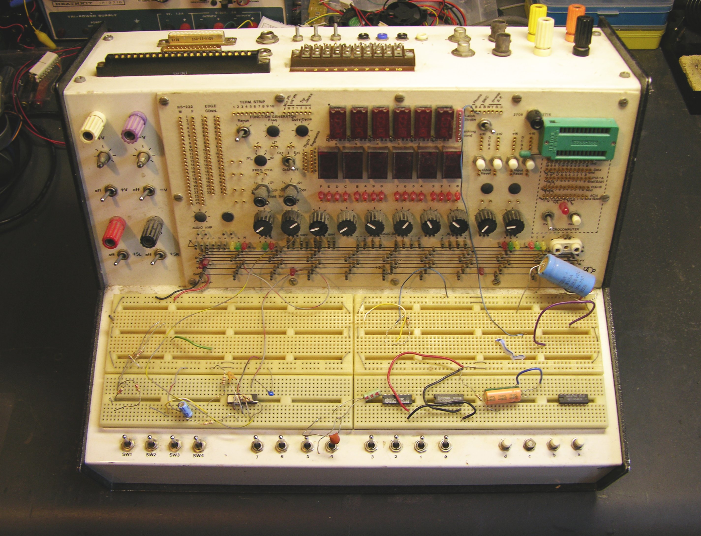
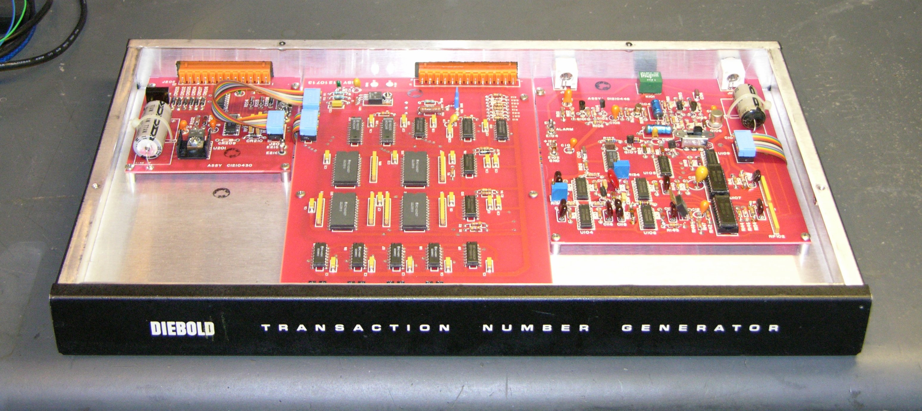
Slim designed and built this himself. To me, it not only is a very impressive piece of work, but also reflects a lifetime of experience prototyping circuits and knowing what features are useful to have at hand. A station like this should come with a manual, and it’ll take me some time to figure it out and become fluent with everything it offers.

Myriad Connnectors

Slim's prototyping station, top view

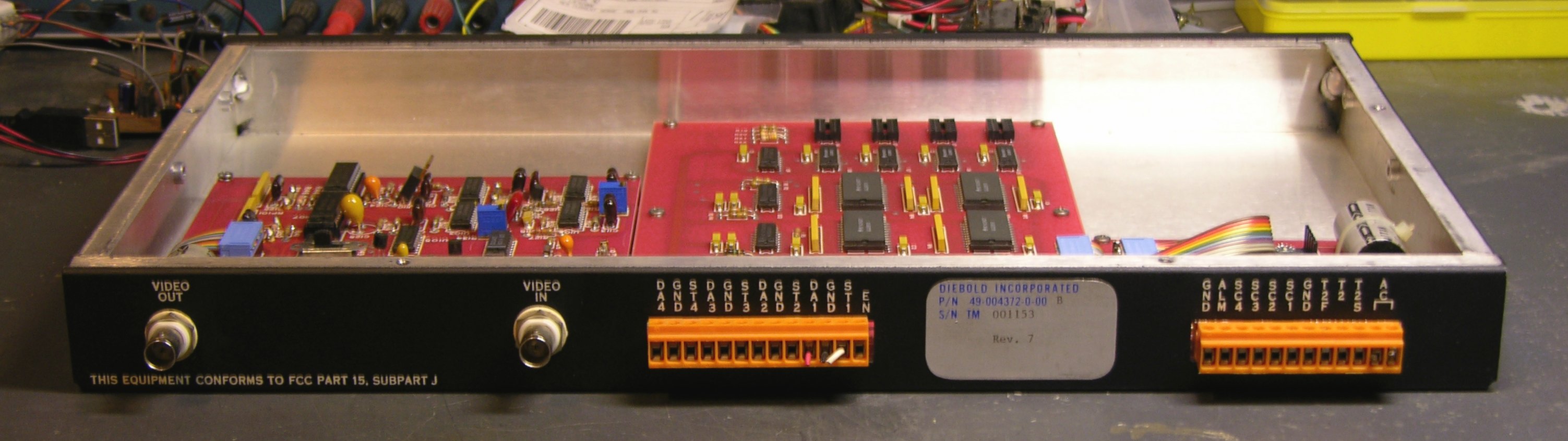
Starting at the top, the station has a multitude of connectors: DB-25 male and female, a card-edge socket that reminds me of my VIC-20 days, 1/4″ and 1/8″ jacks, barrier strip, RCA, BNC, and binding posts.

Slim's prototyping station, breakout of top connectors

Each connector breaks out to well-labelled wire sockets in an area near the left of the front panel. These pin sockets are a Slim signature item — he used them on all of his breakout and prototyping stations, and I’ve never seen them anywhere else.

Next to the connector area, in the right of the photo, is an area for a signal generator that looks like it wasn’t finished. Based on some conversations I had with Slim about signal generators, my guess is that he intended to take the board out of a commercial unit, embed it inside the case, and extend its controls to the front panel, rather than construct his own from scratch.
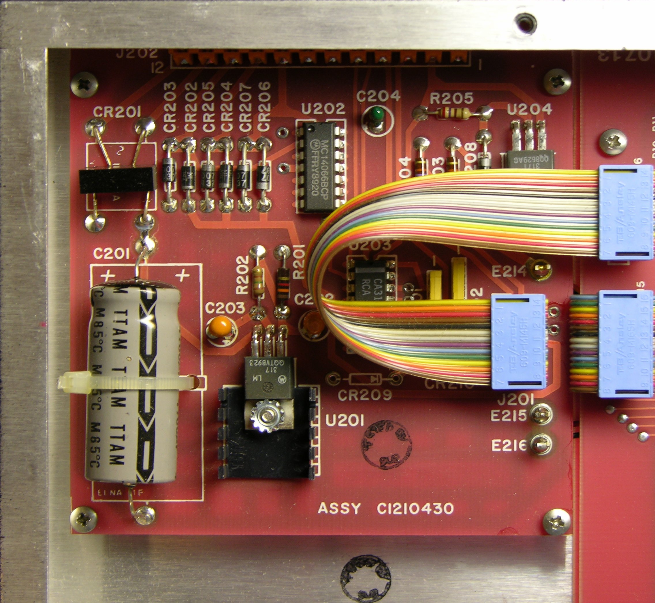
Power Suppply

Slim's prototyping station, power supply

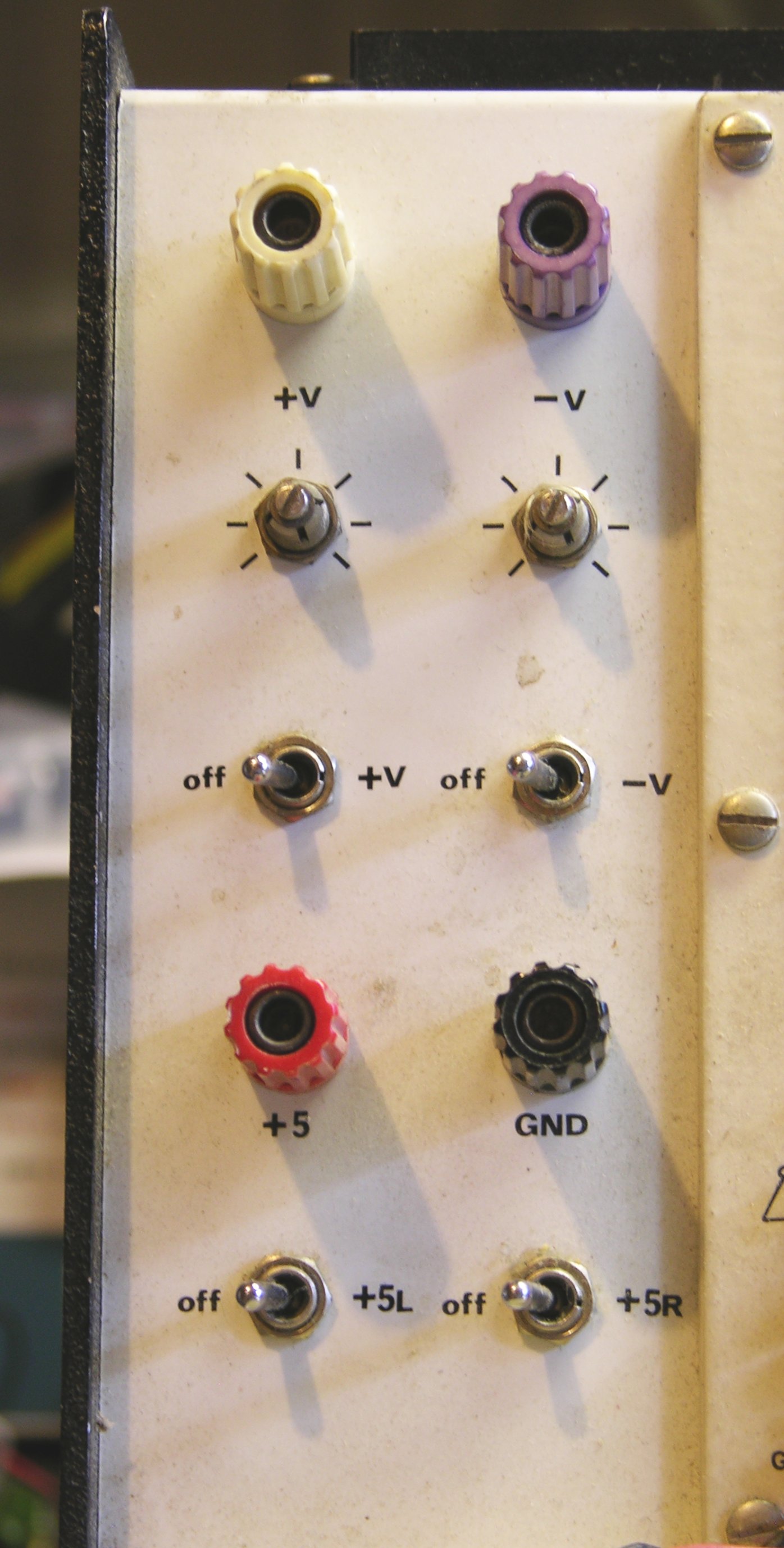
At the far left of the front panel are power supply connections providing variable + and – voltages and dual +5V supplies. If I’m following correctly, the two 5V supplies run to the ends of the rail above the breadboards, and are jumpered down to the left and right breadboard sections from there.

LEDs

Slim's prototyping station, LEDs

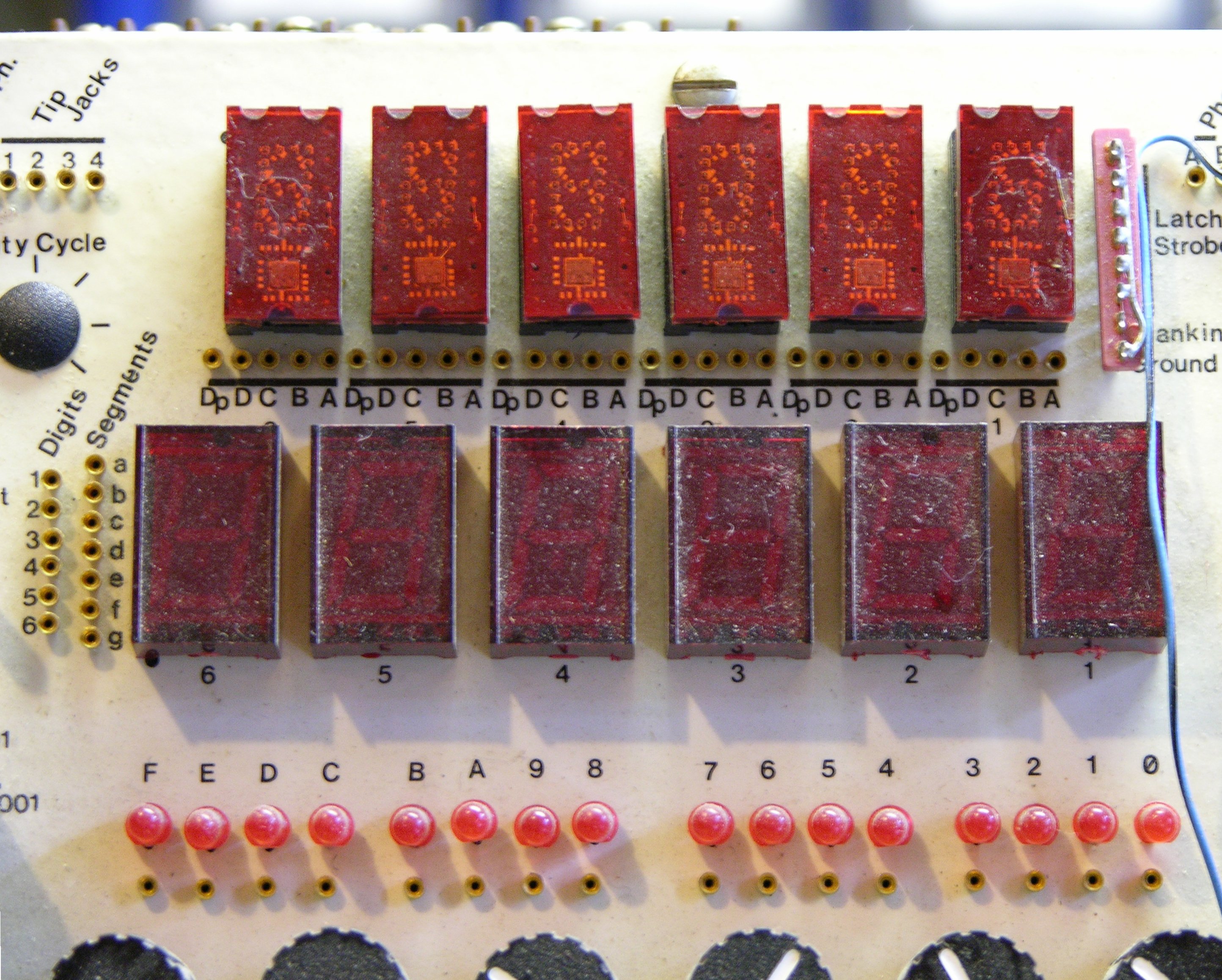
In the upper center are two six-digit sets of seven-segment LEDs. The lower set appears to be broken out for matrix drive (labelled Digits 1-6 and Segments a-g at the left), and the upper set appears to have integral decode/drive (individually labelled A-D and Dp under each digit). There’s also a set of sixteen LEDs for individual use.
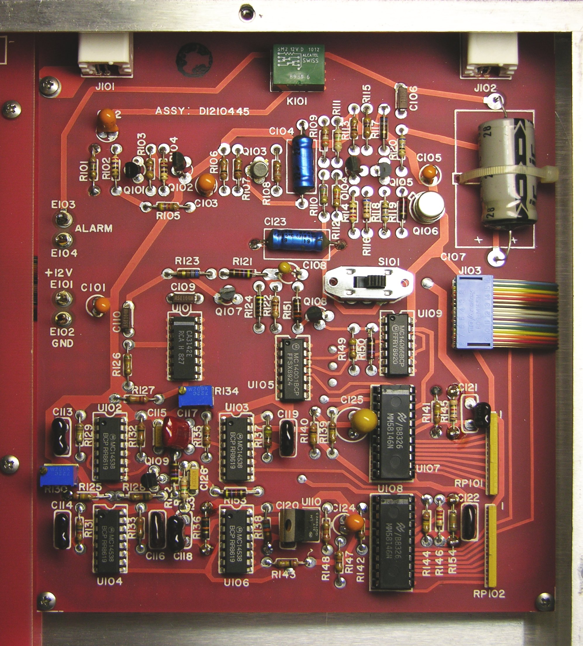
Microcomputer

Slim's prototyping station, microcontroller breakout

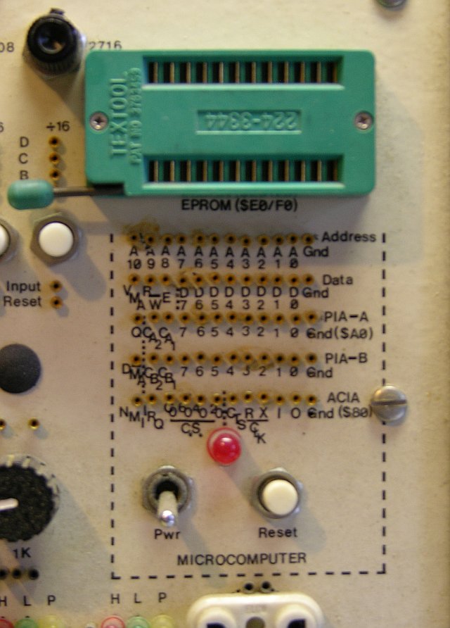
The upper right corner has a microcomputer section with a 24-pin ZIF socket for EPROMs, selectable between 2708 and 2716 (this is old school) and presumably a microprocessor hidden behind the panel. Given the PIA labels, I’d guess it’s a Z80, but it could be something else with an external PIA chip as well.

Everything Else

That’s all the closeup pictures I took, but there are a few more features I’ve already figured out. The row of black knobs across the center are potentiometers of commonly useful values, broken out to pin sockets underneath each one. The row of tracks between the pots and the breadboards delivers power and also has four buses labelled A-D.

Above the tracks are wire sockets for the switches and pushbuttons across the bottom of the case. There appear to be six logic inverters. And at each end are two sets of LEDs labelled H (red), L (green), and P (yellow) — I assume logic probes showing high, low, and pulse.

And of course a breadboard, generously sized, with a bunch of parts still on it. It has a couple of TL064s, Slim’s and Cort’s favorite op-amps, but it doesn’t look like it’s really a circuit in development. It looks more to me like it might be leftover parts that he was moving out of the way.

Using It

My challenge now is to learn to use it effectively. I always have enough clutter on my workbench that I have preferred using small breadboards and pulling out only the parts and connectors I need at the moment. On the other hand, the benefit of a prototyping station like this is always having everything at hand, saving the time of having to dig out the right connectors and displays.

It’ll definitely take some to get used to, and to determine which method really works best for me. Maybe eventually, it’ll inspire me to build my own comprehensive station that’s just right for me; and with Cort’s help, hand Slim’s station down to the next generation of experimenter.

Inside a Diebold Transaction Number Generator

Sunday, September 23rd, 2007

I’ve been swamped at work lately and it’s been spilling over to home, so I haven’t done much with CNC (or other projects) for several weeks. But I bought this Diebold Transaction Number Generator on eBay for $10, out of sheer curiosity to see what was inside. I have no idea what it’s supposed to do, and can’t find any information about it online, but industrial security and crypto equipment fascinates me.

Diebold Transaction Number Generator, front view

My goal was not to reverse-engineer the whole thing, but to get a rough idea how it worked and look over the interesting bits. I think I’m not alone in that when I get a new electronic device, I like to look inside to see what they used to make it work.

Diebold Transaction Number Generator, rear

The back panel has video in, video out, and screw-clamp wire connectors:

(Nearly) all of my blog pictures are links to the full-resolution version, so you can click to zoom on this, but I’ll save you the trouble. Here are the labels over all the wire connectors:

D
A
4
G
N
D
S
T
4
D
A
3
G
N
D
S
T
3
D
A
2
G
N
D
S
T
2
D
A
1
G
N
D
S
T
1

E
N
G
N
D
A
L
M
S
C
4
S
C
3
S
C
2
S
C
1
G
N
D
T
2
F
T
2
A
C
⌈   ⌉

Okay, so I get what “AC” is, and “EN” might be enable, and “ALM” looks a lot like alarm, and there sure are a lot of ground lines, but the rest of the connections pretty much escape me. The DA-GND-ST triples make me think of some kind of balanced transmission, but wouldn’t a balanced transmission line have a shielded connector instead of a terminal strip?

And why video? Does this box generate transaction numbers and superimpose them on a video feed? I dunno. But it sure is pretty inside. Let’s have a look.

Diebold Transaction Number Generator, interior

I really dig the red circuit boards (red solder mask). Green solder mask predominates these days, and I’ve seen blue and other colors, but I’m pretty partial to red.

The small board in the upper left appears to be mainly the power supply. The medium board in the upper right interfaces to the video feed, and the large board in the middle has some interesting digital logic on it.

Power Supply Board

Diebold Transaction Number Generator, small, left board

Here’s the power supply board. The bridge rectifier, CR201, connects to the main AC terminals on the back panel and feeds the LM317 regulator U201. U201 uses R202 (150Ω) and R201 (1.3kΩ) to set its regulated voltage.

The LM317 maintains a nominal 1.25V voltage across its reference terminals, across which R1 thus sets the reference current I1. The reference current also flows through R2, determining the regulated voltage. From the LM317 datasheet,

VOUT = VREF (1 + R2 / R1) + I1 R2

where

I1 = VREF / R1 = 1.25V / 150Ω ≈ 8.33mA

So

VOUT = 1.25V (1 + 1.3kΩ / 150Ω) + 8.33mA 1.3kΩ

    ≈ 1.25V * 1.87 + 10.8V ≈ 13.1V

With a bridge rectifier and capacitor-input filter, output voltage is approximately equal to peak input voltage, which is VAC / √2, so the box is expecting an AC supply voltage of not less than 18.6V; compensating for diode voltage drops gives about 20VAC. Knowing that, I could (if I cared enough) now power it up.

Note the bridge rectifier made of discrete diodes CR202-207 connected to external pins T2, T2F, and ground. CR206 and 207 double in two bridge circuits with CR202-203 and CR204-205, making me suspect that T2 and T2F are not meant to be used simultaneously, but as alternates. On the other hand, T2 heads off to the OUT1 (common) pin of the MC14066 quad analog mux chip. Kind of looks like it’s being switched to one of two different destinations.

Video Board

That’s about as much effort as I care to put into the power board, so let’s move on to the video board.

Diebold Transaction Number Generator, right board

The four chips in the lower left are MC14538 oscillators, there’s another LM317 voltage regulator in the lower center, and the board has a mechanical relay up at the top. But the really interesting part is the two large chips in the lower right: MM58146 on-screen display drivers for television channel indicators. So this box is built to superimpose some kind of transaction numbers onto video. That’s interesting to know.

Logic Board

Diebold Transaction Number Generator, large, center board

On to the logic board in the center, which I’ve rotated here to make the part numbers easier to read. The four chips U5-8 near the empty sockets on the right are MC14495 hex to seven-segment decoders. Whaaaa? I assume the on-screen display driver chips do their own character generation, so why decode binary to seven-segment? Maybe the four empty sockets U1-4 are for DIP seven-segment displays, to show the transaction numbers internally during testing or troubleshooting.

The four large chips in the middle, U11-12 and U14-15, are even more interesting. They’re MC14034 universal bus registers, permitting bidirectional transfer of data between two parallel buses, serial-to-parallel, and parallel-to-serial conversion.

The datasheet tantalizingly offers, “Other useful applications for this device include pseudo–random code generation,” but says nothing further about it. My guess is you’d wire them to shift and output bits, possibly with external inverters to shuffle things around at different stages, to make a hardware implementation of a PRNG algorithm.

You might even be able to wire them up to make a digital version of something like the rotors from a German Enigma cipher machine — but without spending a lot of time tracing pins on the bottom side of the board, I don’t know whether that’s how they’re being used here, or merely for more mundane purposes. It’s not quite worth it to me to figure out exactly how the MC14034s are used, so I’m pretty well done with my exploration.

Conclusions

I didn’t figure out a whole lot about the device, but it’s pretty clear that it takes a video input and superimposes numbers onto it. (One thing I wondered initially was whether it might be using video as a source of random noise to generate transaction numbers.) And it has some interesting bits inside, with logic chips I might be able to reuse for something else. That’s enough to satisfy my curiosity for now.

MP3 of Noise from Baldwin 45HP2 Organ

Tuesday, September 4th, 2007

Here’s an MP3 file of the noise the organ is making. It’s about 24 seconds:

  • The pop of the power switch being turned on.
  • Silence and the noise fading in as the tubes warm up.
  • Loud noise.
  • Faint notes — me playing on the keyboard. I could adjust the manual and pedal volumes to any mix I wanted; that’s just where they happened to be set.
  • Fade out after I turned off the power.

Note that the noise is continuous the whole time the organ is on — not just when playing the keyboard or pedals. And my iBook’s internal microphone didn’t capture the lower octaves of the noise at all — the sputter goes down further than I can hear playing back this sample.

Maybe this helps?

Advice Wanted: Troubleshooting a Baldwin 45HP2 Vacuum Tube Organ

Saturday, September 1st, 2007

Baldwin Electronic Organ Model 45HP2, back open

My friend Lawrence’s son Jacob has just been given a Baldwin Electronic Organ, model 45HP2. It’s big and old and made with vacuum tubes and point-to-point wiring (no printed circuit boards), and it has a problem: The speaker for the pedals (that you press with your feet) continually puts out static that sounds like a low-pitched crackle. It’s definitely not 60Hz hum, nor does it sound like turntable rumble — it’s very irregular in both pitch and amplitude.

Particularly vexing is that the organ was reported to work perfectly before it was moved 60+ miles in a U-Haul-type trailer. So whatever is wrong with it probably has a mechanical origin — a damaged tube, a part or connector that needs to be reseated, or a joint that needs to be resoldered.

Baldwin Electronic Organ Model 45HP2, amplifier closeup

The amplifier chassis has separate volume controls for the manual (keyboard) and pedal (footboard), and turning the pedal volume all the way down eliminates the noise. So it definitely seems to be coming from the pedal section — either a tone generator or the amplifier.

The problem would be easy to repair if it were a simple matter of replacing a bad vacuum tube, so we’ve started investigating in that direction. I had Jake swap the two 12AX7 tubes on the amplifier to see whether the problem followed the tube to the manual speaker, but no change. I should probably have him swap the 616s and 7027s as well.

Baldwin Electronic Organ Model 45HP2, tone generator closeup

The tone generators run across the upper part of the back of the organ, with a column for each note of the scale, two columns per “board.” I believe the connector at the top brings in the “requests” for that tone in each octave — probably in analog form, as a sum of all the different sources needing that pitch (for a fundamental or harmonic frequency).

The boards are presumably the oscillators, and there’s a bus (I assume the tone output bus) made of 1/8″ rods at the bottom of the inside of the cage. My guess is that the pedal tones go onto a different rod in the bus than the manual tones; but without a schematic, with the high voltages I expect are present in a tube system, and with not much time spent so far, I haven’t tried to determine which one. It’d be fruitful to disconnect the pedal tone generator output from the amplifier, to isolate the problem to the oscillator or amplifier section, if we knew which it was.

All of the oscillator tubes are identical (6SN7 GTB), and I did have Jake rotate them within all the oscillators (top two down one, bottom to top), thinking that if an oscillator tube were the problem, the nature of the noise might change if the tube were in a different position. No change so far.

If there’s anyone out there with experience with this type of thing, I’d be very grateful for any advice you want to throw my way.