Archive for the ‘LED Clock’ Category

(Mostly) Assembling My CupCake Motherboard

Monday, May 25th, 2009

The MakerBot CupCake‘s motherboard (RepRap generation 3 motherboard) is Arduino-compatible, connects to all the other boards in the CupCake / RepRap, and has lots of spare connectors to boot.

Ah, spare connectors to prototype, I mean; the spare connectors aren’t needed in order to get the board to boot. Ha ha.

Mostly-assembled CupCake motherboard

I got mine mostly assembled last week. Like every other piece of electronics in my CupCake kit, my motherboard had missing parts — I got five extra 4.7KΩ resistors instead of the five 1.8KΩ resistors. And unfortunately, that was another part for which I couldn’t find replacements at hand — although I did end up sorting and filing a bunch more SMT components while searching.

After waiting a week for the missing resistors as the solder paste was drying out and getting crusty, I gave up and baked the thing without them. I can hand-solder the 1.8KΩ resistors onto the board when they arrive. And because they’re voltage dividers for 5V → 3.3V level conversion to the mini-SD card and pull-ups for the I2C bus — neither of which is needed for basic operation — I can even run the darn thing without them. I just need to get them on there eventually.

Crusty solder paste bakes just as nicely as gooey solder paste, by the way.

Unlabelled R1 on MakerBot Cupcake motherboard

I did spend a while searching for the placement of R1 on the PC board. I eventually found it through a combination of the process of elimination and checking the schematic. As far as I can tell, the name label didn’t make it anywhere onto the silkscreen — can you spot it?

60,000 mcd Sure Sounds Bright

Sunday, November 18th, 2007

I’m still interested in building a sunrise alarm clock, to gradually lighten the bedroom up to full daylight brightness when it’s time for me to wake up. I’d enjoy making it with LEDs, and a blog reader suggested I check out some yellow LEDs from this eBay seller.

They had fifty 10mm 60,000 mcd yellow LEDs for $6.98 plus $8.98 shipping and $2.00 insurance, so $17.96 for the lot or 36¢ each. Seemed very reasonable, and I was the only bidder on that batch, so I won the auction.

The LEDs arrived, and they’re the first 10mm LEDs I’ve bought, and they’re huge. But I put them in my LED tester, and they don’t seem that bright, even at 50 mA. So tonight I put them in a breadboard with 100Ω resistors and cranked up my variable bench power supply. They still don’t seem that bright.

10mm and 5mm LEDs on breadboard

Here’s the layout, so you can see I’m not lying and using different resistor values for different LEDs. The LEDs on the left are the 60,000 mcd yellows, and the ones on the right are the 5mm 10,000 mcd blues I’m using in the LED clock.

10mm yellow and 5mm blue LEDs on breadboard, lit

The yellows are a little more directional than the blues, which was making comparison difficult, so I scuff-sanded all of them to get a frosted, diffuse effect and level the playing field. The blues are pretty clearly brighter.

ceiling

Here’s the ceiling above the breadboard. The yellows are still more directional even after frosting — the whole ceiling is bathed in pleasing, blue light with only a small patch of slightly brighter yellow in the center.

I know that candelas are a measure of brightness within the coverage pattern of a directional light source, whereas lumens are a measure of total light output. Here’s my favorite mcd and viewing angle to lumen calculator, which makes it easy to convert. The seller’s information for the yellows says they have a 10° viewing angle, and I should have thought more carefully about its impact before buying.

At 3 lumen each, and with a 60W incandescent outputting about 800 lumen, I’m probably not going to be able to use these to simulate full daylight. I’ve been starting to consider using dimmable fluorescents instead, in spite of the hassle of having to build an enclosure to protect the bulbs.

I wonder what application only needs a 10° viewing angle.

Lesson: Always check viewing angle and lumen output of LEDs before buying.

LED Clock: Serial Communication, MAX232, and Programming the LogoChip UART

Tuesday, August 22nd, 2006

For precision timekeeping, both to set the time initially and to correct any drift that may occur, I want the LED clock to have a means to connect to a PC. Further, having serial communication available means that a PC could be used to trigger some of the clock’s special modes, like nuclear meltdown. :-) A wireless ethernet connection would be ideal; but I don’t have the time to devote to it right now, and it would add significantly to the cost. Wired ethernet and USB share the same problems. Wired serial communication is easy.

Well, supposed to be easy. The LogoChip has built-in serial communication; the hitch is that receiving data halts the running program in order to process the data. In other words, any time you set the time, the program would stop running and be unable to receive the data. That’s a drawback.

There’s a better way. The PIC chip that runs the LogoChip firmware has a built-in Universal Asynchronous Receiver/Transmitter (UART–a device to run serial communication in hardware). The LogoChip firmware doesn’t use the UART, but I can use it myself through software–and that’s exactly what I’ve done.

Level Conversion and the MAX232

There’s one trick to using the UART: RS-232 specifies ±12V for its signalling, but the PIC chip runs at 0/5V logic levels. The LogoChip gets away with interfacing to RS-232 by using a substandard transmit voltage and a resistor-based divider on the receive voltage; but there’s one more reason I can’t do that when I use the native UART: Line driver chips invert the signal so that 5V source becomes -12V on the line. The LogoChip is doing the inversion in software when it drives its hacky serial ports, but the UART requires an inverting level converter and has no facility to invert for you.

That means I need an external line driver chip (or hack something together with transistors, but I’d rather not), and that means I need a MAX232. The MAX232 not only converts from 0/5V to ±12V, but also does so without requiring ±12V power connections–it generates ±12V from a single 5V supply.

I ordered samples of the MAX232 in three different packages a while back, and received one of my samples and one of someone else’s samples. I’m trying to get Maxim to send me the rest of my samples order . . . but that’s a whole ‘nother story.

Prototyping the MAX232

A week ago, I gave up waiting on the DIP MAX232 sample and soldered leads onto my surface-mount sample so I could stick it into the breadboard. I plugged in the five 1μF capacitors it uses to step up the voltage, wired it to the LogoChip, and got pretty quick success–I could translate voltage levels going in and out. Cool!

Programming the UART

Then I tried to configure the UART so I could send data, and I couldn’t manage to get anything meaningful to go across the link. Not cool!

On the datasheet, the UART looks a little intimidating to get set up, but it’s really not too bad once you get into it. (Well, mostly.) There’s a little more to it; but you mostly enable UART mode (the pins are regular I/O pins if you’re not in UART mode), set the number of bits you want, program the baud rate generator, and drop data into the transmit register or pick it up out of the receive register.

The baud rate generator (BRG) was my sticking point. It’s set as what divisor to use of the oscillator frequency; except I couldn’t find anywhere that said whether that was the oscillator running the chip or one of the programmable timers. Turns out it’s the main oscillator–mostly.

My first problem was a think-o on the write instruction I used to configure the baud rate generator speed–I had the operand and address reversed. The proper syntax is

write <address> <value>

but I wrote

write SPBRG-9600 SPBRG

I don’t know why, but write <address> <value> just feels wrong to me. English uses verb indirect-object direct-object syntax. (“Give me the money.”) I’m pretty sure the old 8-bit microcomputer BASICs used POKE <address> <value>. So what’s my problem???

Anyway, once I got that sorted out, I had a small matter of determining the correct divisor to put into the BRG. I thought I was trying all the appropriate values from the table in the datasheet, but I could never get real text to come out on my computer. Testing was a hassle, too, as I had only one serial port available on the PowerBook, so I had to keep moving it back and forth between the programming port and the UART.

The datasheet says the divisor for 9600bps from a 40MHz oscillator is 64, but I kept getting garbage on my screen. I thought I was also testing all the different receive rates on my computer each time to see whether I was accidentally at some other rate; but even then, I could never find good data. (In retrospect, that’s especially puzzling, since I should have been at different usable data rates a number of times.) I ended up spewing dummy data (capital “U” is 01010101 in binary) from the LogoChip and looking at it on my scope to see what speed it was.

With the BRG divisor at 64, I got one bit measuring about 5.3 divisions at 20μs/div, or about 9420 bits/second. After some fiddling around, that seemed to work properly (and matches what’s on the datasheet for 40MHz), so I thought I was fine. And at that point, I was able to transmit data to the computer.

Receiving Data from the UART

Receiving is much more difficult, apparently, as I was still unable to get data from my computer into the LogoChip. It would just sit and wait for incoming data, and never actually receive it into the buffer.

Since transmit and receive share the same BRG, I knew I didn’t have a speed problem. I wondered whether the MAX232 was bad; but with my scope, I was able to confirm the flow of 5V translated data from the MAX232 to the PIC. I wondered whether the PIC was bad; but I wrote a test routine to take the PIC out of UART mode, and I was able to see changing data levels on the receive pin when accessing it manually.

What the heck???

I knew Tom McGuire had got RS-232 communication working using the UART, and so I asked him about it. He sent me some sample code (which was virtually identical to mine) and some things to check (which were all okay), and then volunteered to help me troubleshoot it. I dropped by last night after work, we hooked it up to his digital scope and saw that data was flowing where it was supposed to, we compared it to more of his code and found it was the same, and so once again, what the heck???

And then we looked at the receive error flags. I’d been wondering whether I was going to have to deal with them, but figured I’d let the master inspect my circuit and code first. But he found some other of his code that examined the receive overflow flag, and when I tested mine, I found it was set. Overflow? The UART hadn’t received any data successfully; how could it overflow???

Well, you clear the overflow bit by taking the UART out of continuous receive mode (and putting it back in). I added code to my receive routine to check for and clear the error, and BLAMMO! Instant working serial communications!

Next Steps

As noted yesterday, I’ve got my board for the first third of the six-digit display laid out (with the other two-thirds requiring simple clone/shift/chop operations). I added some identifying text to it last night, and I have a tentative appointment with Tom on Friday to mill the board.

Meanwhile, I now know that my serial port hardware is all okay. So even though I haven’t written the software to sync time with a PC, I can go ahead and design and build the clock’s controller board.

I should have two-digit display pictures up by sometime Saturday or Sunday . . .

LED Clock: Laying Out the Full Display

Monday, August 21st, 2006

Background and Long Delays

It’s actually been six weeks since I got my one-digit prototype working. Since then, I’ve prototyped the DS1302 real-time clock chip, done troubleshooting on some weird voltage problems, finally fixed the voltage problems, and written a demo of timekeeping with the one-digit display. I haven’t exactly been idle; but I haven’t done anything about expanding the one-digit prototype into a full display.

Well, it’s a slight exaggeration to say I haven’t done anything. About three weeks ago, I cloned the single-digit schematic in EAGLE, edited out the colons and decimal points that won’t be used in the display (between the two digits of the hour, of the minute, and of the second), and got it all to fit onto one “sheet.” But I hadn’t done anything yet about expanding the data bus to make separate latch lines for the six digits, nor had I even started working on a board layout.

Part of the problem was that the freeware version of EAGLE only does board up to about 4″x3″, which was the size of my one-digit display. I knew I was going to have to switch layout software to build a bigger display, and I’m always slow getting around to installing and learning new software. Also, I talked to Tom McGuire, who volunteered to mill a display PCB for me, and he indicated that he couldn’t do a board quite as long as the full display (15-16″). He suggested milling half, rotating around a reference point, and milling the other half, but that sounds a bit tricky to get the alignment just right.

Last week, I finally resolved myself to making the board in three sections, for HH:, MM:, and SS. That makes it easier to manufacture; and if I eventually have a means to make the whole thing in one, I can presumably paste the pieces together into one large layout.

You’re Thinking About Building a Bigger One

Through a strange sequence of events, I was hanging out at Cort’s house Saturday morning, sitting around with Cort and Shannon and Brad talking about various things. I had my PowerBook on my lap and I was tinkering with EAGLE while we visited. That’s right; I finally got back to the clock display.

I saved my six-digit circuit in case I ever want to go back to it, but copied it to a new two-digit layout and chopped out the other four digits. I cut out duplicate connectors and started wiring things together. I laid out the latch lines for all six digits, and set up the bus to have input and output connectors at opposite ends, for daisy-chaining the three boards together (if I choose).

I agonized about how to select/connect the appropriate latch line for each digit. Ideally, I’d like to have DIP headers, and you plug the jumper across the line corresponding to which digit you’re configuring. That would allow reconfiguring one digit as another for troubleshooting, to determine whether a problem was in the controller or the display. Between lack of room on the board to position a full DIP header, and the difficulty of soldering it onto the back side of a single-sided board (so it could be accessed without removing the display from the clock case), I gave in and settled on using a jumper wire to bridge from the latch bus to each digit’s latch line.

EAGLE Circuit → FreePCB Board

I had intended to use FreePCB for designing larger boards, because it looked like a nice package, and I somehow got the impression it could read EAGLE netlists (more on that later), to import part and connection information into a board layout and prepopulate it. FreePCB was designed by an engineer who was dissatisfied with available, affordable board layout software and decided to write his own. He’s done a very nice job!

Only problem is, it does not read EAGLE netlist files. FreePCB reads PADS-PCB format files, and it turns out that’s not what EAGLE outputs. Late Saturday, I tried to transfer my netlist from EAGLE to FreePCB, and quickly found out that the formats are different. Between Google and the FreePCB user forum, the only thing I could find about EAGLE and FreePCB is that the FreePCB author figures EAGLE’s format is pretty simple, and someone could write a translation utility.

So I did. EAGLE generates one partlist file and one netlist file; PADS-PCB has the two combined into different sections of the same file. I wrote a Perl script to parse the EAGLE files and translate into PADS format, and it was really pretty simple.

Except for package types. The export/import files contain an indication of what package type each device has, so the PCB software can prepopulate your layout with appropriate footprints that you just have to drag and drop into place. Naturally, EAGLE and FreePCB use different package names, so I added a hash lookup to translate those as well. Unfortunately, that’ll be the trickiest part of the program–comprehensively identifying and accommodating all the different package types.

By midnight, I had a pretty good translation going and most of the parts placed (but no traces routed) for my two-digit board–and then I noticed that FreePCB doesn’t generate outline milling information. It makes Gerber trace files and Excellon drill files, but nothing for CNC milling. Since I really wanted to be able to mill boards with Tom, and since I insist on being able to mill boards for myself in the future, I quit for the night and waited until I could talk to Tom about options.

FreePCB Board → DeskPCB CNC Mill File

I talked to Tom early yesterday afternoon. I was hoping he had a way to generate outline milling code from standard Gerber trace files, and he pointed me to a piece of software called DeskPCB. It’s $95 for a license, and there’s a time-limited demo available for free download. Generating outline code is exactly what it does–it generates “trace isolation milling and drilling” files out of Gerbers and Excellons. Shows you the original board and the mill pattern right on the screen, too, so you can confirm it’s doing what you expected.

It’s pretty slick! And that means I now have a complete path from circuit design to board production:

EAGLE for circuit design
    → export EAGLE-format netlist and partlist
    → Keith’s script to convert to PADS netlist

→ FreePCB for board layout
    → create Gerber and Excellon files

→ DeskPCB for outline milling
    → create G-code

→ LinuxCNC (née EMC) for CNC mill control
    → mill a board

Very, very cool.

You Doin’ Anything with All That Fancy Software???

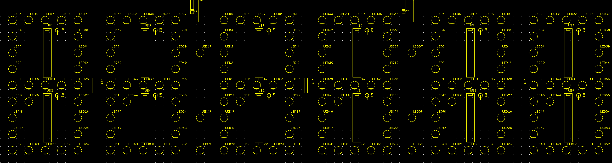
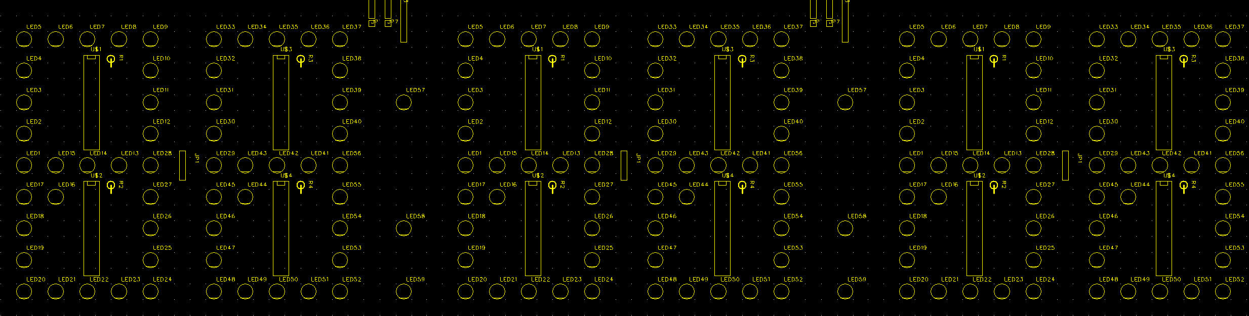
Yup, sure am. I sent Jeremy a screenshot of the two-digit parts placement to stitch together into a six-digit display so we could check the spacing. My first version had .6″ between adjacent digits and .4″ between the digits and the colon.

Six-Digit Layout with .4" to Colon

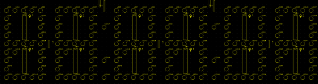
From across the room, that looked like there wasn’t really enough separation to the colon, so I asked Jeremy if he could scoot them another .1″ or .2″ apart.

Six-Digit Layout with .6" to Colon

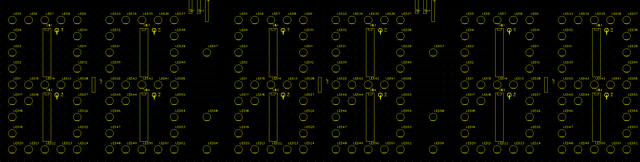
The second version with .6″ on each side of the colon looked good enough that we’re going with it. It’ll be hard to know the exact effect until we see the real thing, but this is close enough to build the first clock. If we want to change the spacing from the first to the second, it’ll be easy enough to do.

I used my single-digit layout as a reference for placing most of the traces on the two-digit, and got all of the new stuff (different power layout, six-digit latch bus) incorporated as well. By late last night, the entire board was laid out and ready to produce.

I’ll still look at it to see whether I can reroute traces to eliminate some of the jumper wires, and I still need to put design and contact information onto it–but it’s a working design that I could now produce if I chose, and that feels great! Tom has Fridays off and offered to take me to his office on a Friday to mill a board, so I’ll see whether I can set something up for this week.

Next Steps

Because the margins around the perimeter of the display aren’t the same as the inter-digit spacing, I’ll actually have three different boards for HH:, MM:, and SS. I’ve laid out the board for HH:, and it’s a trivial matter of spacing to change the board outline for MM:, and spacing and chopping the colon to make the SS. I feel I should build and test the entire HH: board before producing the other two, so I hope to assemble the first board this coming weekend.

At 174 LEDs per full display, plus 31 already used for the prototype single digit (which I don’t plan to disassemble), I’ll only have used 379 of my 498 LEDs, leaving 119 unused–enough that I could comfortably leave an entire HH: board (59) assembled as a working prototype rather than a production board. I’d be happy for it to be the first real board for a clock, but it doesn’t have to if something doesn’t work out.

I have four sample A6276 LED driver chips, enough to power two digits. I’ll need to order more before I can build the entire display.

Tom was planning to help me debug some UART problems (which I haven’t blogged yet) tonight, checking timing with his digital scope and stuff. After that’s ironed out, I can move the controller circuit from breadboard to EAGLE and lay out and produce the controller board too.

We’re getting closer!

LED Clock: DS1302 + A6276 = Visible Demo

Sunday, August 6th, 2006

After the big victory of getting a bright blue digit working, and the lesser victory of getting the RTC chip communication working, plus some time away from home, I’ve been stalled on the clock for a while. I gave myself a kickstart yesterday by connecting both the DS1302 timekeeping chip and the one-digit display at the same time, and writing some demo code to flash the current hour and minute one digit at a time.

Enough Controller Pins

I had written previously about whether I was going to have enough pins on the controller to run all the different lines I need to hook up. Now that I’m a little further along in development (working prototypes of different parts, settled on the choice of RTC chip), I think I’ve nailed down the exact pinouts I’m going to use:

Pins Subsystem Signals Function / Notes
A0 RTC CE enable
A1 RTC I/O I/O
A2 RTC SCLK data clock
A3-5 unused . .
B0 display SDI data input (to display)
B1 display CK data clock
B2-7 display L0-5 data latches for six digits
C2 display /OE display enable
PWM output for software dimming of display
C6 UART TX transmit
C7 UART RX receive

It seems positively serendipitous that I’m able to use the built-in UART for time synchronization and the one free PWM output for software display dimming without overriding any of the LogoChip’s firmware functions, and everything still fits. I even have a few pins left over, if I think of something else I need to add.

Port A and Analog Inputs

I’d had trouble using A0-2 to control the A6276, and Muaz (in a comment) and I both assumed it must have something to do with the analog inputs (even though I was only outputting to the pins). Looking over the PIC18F2220/2320/4220/4320 datasheet, I can’t find any reason for that–when the pins are set for output, they’re simply outputs like any other pins (although the A/D converter is available at any time, so you can always measure the actual voltage on the port regardless of mode or direction–how curious).

However, since I’ve now moved the RTC to port A (so port B can be used contiguously to drive the display), I needed to be able to use the pins as digital inputs; and I was pretty sure they were configured for A/D when in input mode.

Indeed, the LogoChip language reference says that pins A0-3 and A5 are configured as analog inputs on boot. So I studied the PIC datasheet and wrote a function to configure them as analog or digital as desired. I had guessed that there’d be a bit-wise control register like the I/O port tristate registers; but in fact, there’s a register nybble that simply contains a count of how many analog ports you want; and the PIC makes the right number of ports analog in order from the list A0, A1, A2, A3, A5, E0, E1, E1, B2, B3, B1, B4, B0 (with the E ports only available on 4×20 chips); which is kind of a clever way of doing things.

Here’s my library routine:

  • ad.lib – Library routine to set number of analog inputs

Here’s the code:

;   Keith Neufeld
;   05-Aug-2006
;
;   LogoChip library to configure the number of analog inputs, which
;   start on port A and work into port E (on the 4320) and port B:
;
;       A0, A1, A2, A3, A5, E0, E1, E1, B2, B3, B1, B4, B0
;
;   (PIC18F2220/2320/4220/4320 Datasheet, p. 4)
;
;   Lines set as analog inputs also function as digital outputs,
;   depending on the settings of their port's tristate register.  Lines
;   not set as analog inputs function as digital I/O.
;
;   The PIC sets all possible inputs to analog on powerup (Datasheet
;   p. 50), which the LogoChip firmware overrides to five (A0-3 and A5;
;   LogoChip Language Reference, p. 7).

constants [
    [ADCON $fc1]                        ;   port A control register
        [PCFG-MASK #00001111]           ;       mask for port config bits
                                        ;   Datasheet p. 214

]

to config-analog-lines :number
    if (:number < 0 or :number > 13) [  ;   only 13 lines possible
        stop
    ]

    ;   Preserve high nybble and set low nybble to %1111 minus the desired
    ;   number of analog lines.
    ;
    ;   *ADCON = (*ADCON & !PCFG-MASK) | (PCFG-MASK - :number)
    write ADCON (((read ADCON) and (not PCFG-MASK)) or (PCFG-MASK - :number))
end

I told a little fib–the PCFG (port config) nybble actually contains the bitwise inverse of the number of lines configured as analog, as the code shows.

Integration

So . . . I set the PIC for 0 analog inputs, moved the DS1302 interface to A0-2, and it still works fine. Glommed together the demo code for the DS1302 and one-digit display:

constants [
    [spew-on-msec 200] [spew-off-msec 30]
]

to ds1302-a6276-time
    ds1302-read-clock

    a6276-display-digit nybble-high ds1302-get-hour 0 0
    mwait spew-on-msec
    a6276-off
    mwait spew-off-msec

    a6276-display-digit nybble-low ds1302-get-hour 0 0
    mwait spew-on-msec
    a6276-off
    mwait spew-off-msec

    [. . .]
    a6276-display-digit nybble-high ds1302-get-minute 0 0
    [. . .]
    a6276-display-digit nybble-low ds1302-get-minute 0 0
    [. . .]

And I now have a nice little demo which, upon power on, flashes the digits of HH:MM up onto my display, one at a time, with no host computer attached. Perfect.


It’s a little hard for me to read the digits in the video, due to some combination of my wireless connection, the persistence of my PowerBook LCD, and the low CPU power. But I tweaked the timing pretty carefully to make sure each digit displays long enough to register what I just saw, and that the inter-digit blanking is long enough to distinguish repeated digits. (I want the digits to flash fast, but I’m not trying to build a persistence of vision project.) It looks pretty good on my wife’s PC where I dock the camera to upload and preview the video clips, so I hope the web video okay for everyone but me. :-)

Code Cleanup

Right now, I have DS1302 and A6276 code split off into separate libraries (good), but the actual port pins hardcoded into the libraries (bad). That means when I change my mind about where to plug something in, I have to edit the library code–and that means if I’m using the library for more than one project, I just broke the other programs, so it’s not really a library.

What I really need, linguistically speaking, is lambdas–the ability for a function to return an anonymous function (or function pointer) that has parameters of the generator function coded into the returned function as constants. That is, I’d call

setrtcfunc ds1302-init porta 0 porta 1 porta 2

and now rtcfunc contains a function I can use to access the DS1302 that’s on A0-2.

Aw, heck, I admit what I really need here is an object generator and to use method calls against it to perform further operations; but I hate OO faddists and would much rather sound cool talking about functional languages.

At any rate, much to my surprise, :-^ LogoChip Logo doesn’t support any of those things. So I’ll settle for only being able to use one DS1302 per PIC (which for me is like, uh, pretty realistic); and I need to write an init routine to stuff the port selections into local (er, global) variables so the library is really general-purpose again. But that means putting code into all the function calls to make sure that the port selection has been initialized and aborting if not, and that means deciding whether/how to alert the caller that something went wrong, and that means more thinking, and I’m not so much in a thinking mood right now.

I’m Waiting On . . .

I have a MAX232 RS-232 line-level driver on the way to interface the PIC’s UART to the PC. Once I get that, I’ll breadboard it, write proof-of-concept code to show that I can make the PIC talk to a PC without the LogoChip halting its program to listen (like it does on the LogoChip’s software-based communications and reprogramming port) so I can later write PC time synchronization code. Then I’m ready to lay out the daughterboard for the controller, W00T!

I’m still fussing with expanding the single-digit display into the full six-digit. I made the single-digit display with only a single latch line (and I need one for each digit of the full display) and power traces that are totally inadequate for the ~4A the full display is going to draw. I’ve cloned the digit six times over on the schematic, but haven’t finished touching up the latch and power lines.

And then I’m going to have to learn FreePCB, because EAGLE Free/Light only does boards up to 80x100mm (~3.2×4″) and even EAGLE Standard ($200 each for the circuit design and board layout modules???) only does 160x100mm (~6.3×4″); so I’d have to go up to EAGLE Pro ($400 each for design and layout?!!), and that ain’t gonna happen.

Time to learn FreePCB, which costs $0, makes boards up to 60×60″, recommends using EAGLE for circuit design and export . . . and only runs on Windows. Sigh.

LED Clock: $6 Refund for Wrong Resistors

Tuesday, July 25th, 2006

Best Hong Kong never responded again to the claim/dispute process; and when their time ran out last Saturday, PayPal decided in my favor with this message:

We have concluded our investigation into your claim.

We have decided in your favor and have recovered funds from the seller. You have indicated that a partial refund amount of $6.00 USD would be satisfactory.

If the seller’s account has insufficient funds to complete the refund owed to you, please be assured that we will take appropriate action against the seller’s account, which may include limitation of the seller’s account privileges.

And both PayPal and Citibank show that $6 has been transferred from Best Hong Kong back to my credit card, so I guess we’re done here.

Curiously, PayPal’s dispute resolution center has a rather different message when I view the closed case:

We have completed our investigation of this case. We have denied this claim and a refund will not be issued.

Now, I know it’s already been issued, but that kind of message is troubling. So I’ve submitted this to their customer support:

I recently received an email from you saying you had completed your investigation of buyer complaint case #PP-179-609-629, had decided in my favor, and had provided a partial refund as I requested.

However, I just went into your Resolution Center to view the ticket online, and it says you denied the claim and no refund will be issued.

I’m a little concerned by that. Can you explain the discrepancy between the two messages?

LED Clock: It’s the Voltage, Man (DS1302)

Monday, July 24th, 2006

Well, the DS1302 now seems to be working off my 5V supply–dropped down to < 4V.

The Discovery

Earlier I had realized that I didn’t know whether the read failures were associated with having a 5V supply or having supply from VCC2 (primary). Tonight I swapped the power supply connections, so the lithium cell was connected to VCC2 (primary) and the bench supply was connected to VCC1 (backup). The read failures still occurred when the chip was running off of 5V; so the problem had to be associated with voltage, not supply pin.

The Cure

The datasheet has this to say about the supply voltage:

PARAMETER MIN TYP MAX UNITS
Supply Voltage VCC1, VCC2 2.0 3.3 5.5 V

5V is within the recommended operating conditions–but 3.3V is preferred. So I added small-signal diodes between the 5V supply and VCC2 until I got down to 3.4V, at which point everything worked.

Curiously, it took four diodes to drop 1.6V, or about .4V each–not the .7V that I’d expect from silicon diodes. Granted, I can’t find a datasheet on them (1N9148); but I really doubt they’re some new exotic that I just happen to have lying around in my parts bin.

My best guess is that the 1302′s operating current is so low (in the .5 – 1mA range) that the diodes are operating below the knee. (To paraphrase Captain Barbosa, we like to think of .7V as more of a guideline.) The knee of the curve is the point at which slight increases in voltage across the diode result in rapidly increasing current. Conversely, if the diode current is externally limited below the level of the knee, the voltage drop across it can be less than .7V. I seem to recall doing a lab on this at PSU.

I’m disinclined to acquiesce to putting four small-signal diodes on the power supply of my timekeeping chip, so I guess I’ll look for a Zener in the 3.5V range. It needs to be more than 3.2V (the lithium cell’s 3.0V plus a .2V margin) to keep the chip from switching to secondary power; and it needs to be less than 4V (but I don’t know how much less), because that’s the last reading I took while it was still malfunctioning before adding two more diodes and dropping VCC2 down to 3.4V.

Best of All,

The burst write now works, so I can set the date and time with a single function call. I can only speculate that whatever was screwing up the reads was also screwing up burst writes.

That is, everything now works on the DS1302. I think I’m supposed to be elated at this point, but I’m strangely not. Maybe I’m waiting for it to fail again. Because at this point, given that it doesn’t work even when I’m operating it within specifications, I can’t figure out what changed between when it did work and when it started not working; or alternately, I can’t figure out why it ever worked.

LED Clock: Troubleshooting the DS1302 Interface

Monday, July 24th, 2006

My LogoChip is still reading garbage from the DS1302 when it (1302) is powered at 5V and good data only when the 1302 is running off the backup battery at 3V. I spent some time looking at it this weekend and discovered a number of interesting things (which aren’t all related to the voltage problem), but no solution yet.

LogoChip Logo Include Files

Because LogoChip Logo has no documented means to reference or include other files into code, I was doing something hacky and ugly with m4. Yesterday, I accidentally (by loading the wrong file into the LogoChip console and getting a different error message than I expected) discovered that LogoChip Logo does support an include command: include foo (no punctuation required).

That’s fantastic news, because it allowed me to clean up all the m4 ugliness, do away with the need for a Makefile, etc. I switched all of my DS1302 code to use the native include command, and will do the same for the 6276 code the next time I work with the LEDs.

Burst Write Not Working

The DS1302 supports burst read and write operations, where you access multiple memory locations sequentially. I know my burst read operation works, because that’s how I’m pulling the complete timestamp out of the device to display in my test code. But for some reason, my burst write doesn’t work–I can only set the time using individual write statements, not using the burst write.

I’ve corrected two problems with the burst write code already. I had somehow forgotten to send the burst write address to the device, so I was trying to read from the clock chip without it having any idea what it was supposed to be sending. And I had omitted the control register from the end of my burst because I didn’t want to change the control bits. However, I reread in the datasheet that a burst write to the clock registers isn’t committed until all eight bytes have been written, so I added a dummy write for the status register (which contains only a write-protect bit that I don’t want to enable anyway).

Still no joy. I’m starting to feel like I’ll need a logic analyzer to solve some of these problems.

5V / 3V

A handful of experimental observations about whatever’s going on:

  • Writing to the device registers only works at 5V, not at 3V. (Writing at 3V doesn’t change the values in before/after read tests.) Reading the registers only works at 3V, not at 5V. (Reading at 3V gives garbled but repeatable results.)
  • The problem doesn’t appear to be dependent on the source of the 5V supply–the results are the same when running the LogoChip from a battery and the DS1302 from the bench supply, both from the Curiously Strong LogoChip battery, or both from the bench supply.
  • The problem doesn’t seem to be specifically timekeeping related–I get similar results reading/writing the clock registers and reading/writing the 31-byte NVRAM that the 1302 provides.

It just occurred to me while writing this that I don’t know whether the problem is related to the 1302′s operating voltage or its supply source–that is, whether the difference is that it’s running on 3V instead of 5V, or that it’s supplied by VCC1 instead of VCC2. That’s definitely worth trying tonight.

LED Clock: DS1302 Unworking

Friday, July 21st, 2006

I did some refactoring on the DS1302 code last night: moved driver code into a library, demo code into a program, wrote some print routines to send single nicely-formatted times to the LogoChip console, updated the Makefile, etc. I had a few minutes before breakfast today, so I went to my workbench to see whether the 1302 still had correct time.

Unfortunately, I found I had left my bench power supply on, so I didn’t get a real test of the backup battery. Stranger than that, I was getting garbage data from the 1302 again, and changing the data clock timing didn’t have any impact.

Strangest yet, when I shut down the bench power supply to see how the garbage would change when the 1302 was off, I started getting the correct time. This seems especially strange, as most timekeeping chips shut off all communications and go into a powersaving mode when primary power disappears.

<Scooby>Uuuhhhhhh???</Scooby>

Turn it back on, garbage. Off again, correct time.

The only thing that even halfway makes sense is if I had VCC2 and VCC1 swapped, and the chip was using the power supply as a backup power source when the battery failed (ha ha). But I’ve checked and checked, and I have power to VCC2 (pin 8 ) and battery to VCC1 (pin 1), which is what the datasheet says, even though the designations seem backward to me.

Not sure how to go about troubleshooting this, but maybe something will come to me by the time I get back to it.

LED Clock: Working DS1302 RTC Interface!

Thursday, July 20th, 2006

After the huge psychological reward of getting the LED digit working, I haven’t felt much like getting back to the real-time chip, knowing any successes there would feel insignificant compared to the bright blue glow of the LEDs. However, that’s the recipe for shelving a project indefinitely; so tonight [last night, by the time I finished writing this up] I went back and gave it a go.

Backup Battery

I had got some PC motherboard backup batteries (3V lithium button cells) from my friend’s son Phill as he emptied his “warehouse” in preparation for leaving to college. He had stuck all the cells together between two strips of masking tape, and they’re all covered with goo. I cleaned a couple of them with Goo Gone a while back, and was astounded at how shiny they are–they look newer than anything I’ve ever noticed inside a PC. [Need to remember to add a photo.]

I had also desoldered a couple of holders from dead motherboards. The first thing I did tonight, as a warmup, was plug the backup cell into the circuit and wire it into the RTC and the external crystal. It works–more on that later.

Ground

Made a mistake I’m pretty sure I’ve made before–forgot to connect the ground between the LogoChip and the RTC breadboard, so it was floating again. (That’s not the same floating ground I wrote about earlier, though–that was an off-by-one error when I meant to connect the ground pin on the chip and connected nothing instead.)

I/O Clock Timing

I was getting random data again, though, which was really frustrating. Finally I went to set up a debug mode to take the I/O clock down to 5Hz (yes, 5 Hz, to make it slow enough to watch with a logic probe, since I don’t have a working logic analyzer), and I started getting correct data.

That told me my problem was clocking the data too fast; and as it turns out, increasing the delay after toggling the clock line from one no-op to two is enough to get completely reliable data (at least as far as I’ve been able to determine). Furthermore, this eliminated the weird bit-7-is-always-on problem I’d been experiencing previously in the seconds register.

Real Time

With those problems solved, I’m actually able to get realtime out of this chip! I had previously written code to batch-read all of the time registers, cache the result, and pick it apart into separate values; and I now wrote a routine to use that and print out the individual digits of the time to the LogoChip console. I called it from the console prompt like this:

loop [ ds1302-print-hhmmss wait 10 ]

And was able to get a real-time display like this:

2
0
5
1
0
5

2
0
5
1
0
6

2
0
5
1
0
7

I guess that didn’t turn out to be as much of a let-down as I thought it would! :-) Also, the backup battery is connected properly, because I was able to power off the circuit, bring it back up, and still have correct time.

Next Steps

The times are getting printed vertically because LogoChip Logo always sends a newline terminating each print statement. I’ll update the code to send ASCII values instead, so I can print the time horizontally in a normal format.

For now, I’ve just been playing with HH:MM:SS. Eventually I’ll need to add date processing, to handle DST changes.

There’s also some code cleanup to do, plus some refactoring (rearranging the code to work the same but be in a significantly different [and hopefully better] format). I’m used to being able to use code libraries, but LogoChip Logo doesn’t support them, so I’m hacking my own method using the m4 macro preprocessor and make to glom source files together. I’ve already refactored my 6276 LED driver code that way, and part of the process is carefully defining separate namespaces (since LogoChip Logo also doesn’t have local variables). I’ll want to do the same with this.

And it looks like it must be PC board time . . . Tom McGuire volunteered to help me make the large boards for the full displays; and I need to make a small carrier board to breakout the DS1340 from SOIC to DIP for prototyping. That also means some more refactoring of the 1302 code–I need to be sure to separate the interface code that talks to the chip from the timekeeping code that delivers numbers to the clock, so the timekeeping code can operate independently of which RTC chip I select.