Archive for the ‘TechArt’ Category

Solar Charging and Switching Circuit for Outdoor Sculpture Installation

Sunday, May 29th, 2011

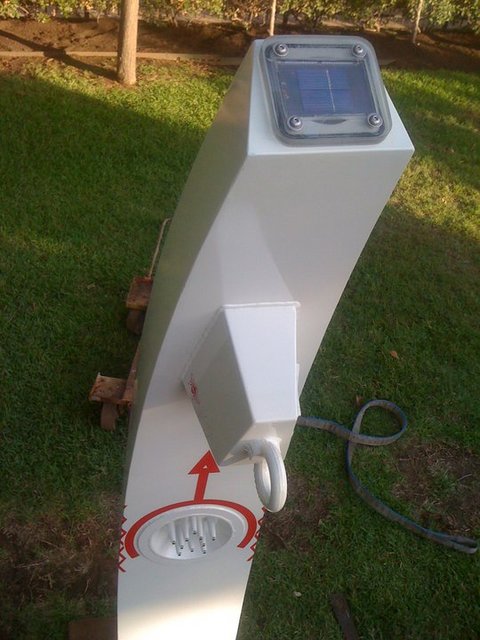
Over the winter, my friend Steve Atwood got a commission for a sculpture to be installed in the Wichita Falls, TX Kemp Center for the Arts “Art on the Green” sculpture garden from May 2011 – 2012.

Lure 22 V2.0 by Stephen Atwood at Kemp Center for the Arts, Wichita Falls, TX

He had in mind to continue a series of his sculptures based on the form of a fishing lure but wanted to enhance this sculpture with one or more LEDs, preferably that would come on only at night. We discussed a wide variety of options that we hope to develop for another installation in the future; but in the end, in the interest of time for this project, Steve found control modules that flash up to five LEDs at random and installed them behind a set of cones protruding from a recessed panel.

He asked how to make the LEDs turn on at night and also wondered whether he could power them for a year from a primary battery or whether he should use rechargeables.

Lure 22 V2.0 by Stephen Atwood at Kemp Center for the Arts, Wichita Falls, TX

About seven years ago, I had come into possession of some discarded solar yard lights, and out of curiosity had reverse-engineered their charging and control circuits. Since yard lights accomplish both functions — charging and switching — I figured the circuit would be perfect for the sculpture. I was able to find one and instruct Steve how to modify it for his needs.

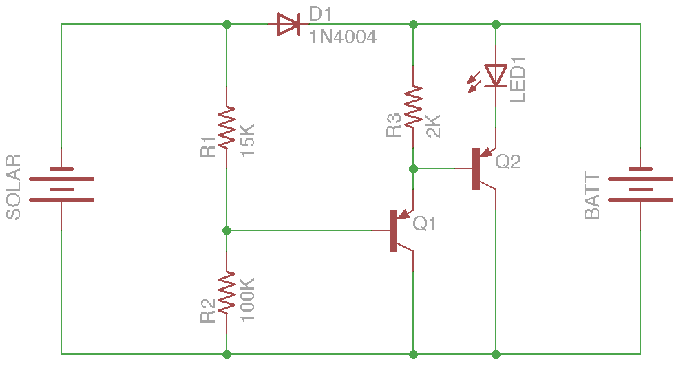
Solar yard light schematic

The circuit is very simple and I find it rather elegant. During the day, the solar panel assembly (left — for want of a proper schematic symbol, I just drew another battery) charges two AA cells through a diode that prevents the battery from damaging the panel with reverse voltage at night. Additionally, through the R1 – R2 voltage divider, the solar panel pulls up the base of Q1, switching it off and allowing R3 to pull up the base of Q2, switching it off and switching off the load LED1.

At night, the panel’s output approaches 0V and R2 pulls down Q1‘s base, causing Q1 to conduct and pull down Q2‘s base (in a Darlington-like arrangement — I don’t know whether it’s still considered a proper Darlington with R3 pulling up the Q1 emitter – Q2 base connection), switching on Q2 and LED1. In fact, depending on the panel’s exact voltage, the load may switch on even before full darkness, and R1 – R2 can be tweaked to tune the turn-on point.

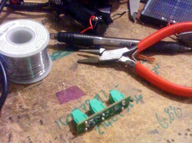
Control board from solar yard light, modified

Steve removed the LED from the control board and replaced it and the fly wires for the solar panel and battery with screw-terminal connectors for ease of installation inside the sculpture. He bought a new solar panel with a higher output voltage to charge the higher-voltage battery for the white LEDs he wanted to use (the yellow LEDs in my yard lights didn’t require as high a forward voltage) and milled a Lexan cover for it to protect the panel from hail, with an O-ring groove to protect it from rain as well.

With higher battery and solar panel voltages, Steve indicated the load was turning on before the ambient light got as dark as he wanted, so I told him how to locate R1 and replace it with fly wires to a 100K pot. After the swap, he said he was able to tune it perfectly and he was delighted.

Lure 22 V2.0 by Stephen Atwood at Kemp Center for the Arts, Wichita Falls, TX, night view

I’ve not had a chance to visit the sculpture garden and probably won’t while Lure 22 is installed. If anyone’s in the area, I’d love to hear from you how well it’s working and how well the electronics hold up over the course of a year outdoors.

Does Used Tinnit Ever Work?

Friday, January 21st, 2011

The board being too long for my Pyrex dish and the overlap in the middle notwithstanding, this dull, mottled finish is typical of what I get every time I use TInnit other than the day I mix it.

PC board after tinning in used Tinnit

The precipitate never re-dissolves; and I’m guessing that the salts sitting directly on the board are what cause the mottling.

I find this curious, as I mixed this batch only two weeks ago, when it worked noticeably better than this … although now that I mention it, I think even then it produced duller results than it has in the past. Perhaps I exceeded the shelf life of the unopened package, so perhaps I’m being unduly hard on the Tinnit; but I’ve had the same problem before.

PC board after tinning in Tinnit and wet-sanding

I’ve been having good luck lately with scouring pads to shine up the boards; but tonight I had to resort to wet-sanding. Turned out fairly well.

No, that’s not how I typically lay out circuit boards.

Yes, I’ll be posting a lot more about what I’ve been doing for the last month as soon as Steve and I get his sculpture delivered to the gallery before 17:00 tomorrow.

Wired IV

Friday, May 22nd, 2009

The video from this year’s Technology: Art and Sound by Design final show is now posted:

Wired IV from MRC Video Services on Vimeo.

And I’m very impressed with our students’ write-ups of their projects on the class blog, including pictures, video, circuit diagrams, and Arduino and Pd code.

Go students!!!

LM34DZ Fahrenheit Temperature Sensor

Monday, February 2nd, 2009

This started as notes I made to myself long ago for the LogoChip, but they apply equally to the Arduino A/D converters.

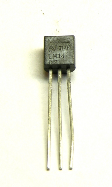
The LM34DZ is a temperature sensor in a TO-92 case available from All Electronics for $2.50. It has the handy characteristic of reading an output voltage that directly corresponds to Fahrenheit temperature in a ratio of 10mV per °F. That is, at 70°F it reads 70 * 10mV = 700mV.

LM34DZ Fahrenheit temperature sensor

With a direct output voltage (rather than the varying resistance that many thermal probes provide), it’s perfect for hooking to a microcontroller A/D input. So, how to convert the A/D reading back into Fahrenheit temperature?

Well, the sensor reads 10mV (or .01V) per °F. Microcontroller A/D converters tend to have 5V input and read 1024 steps over the 0-5V range.

1024 steps / 5V ≈ 205 steps / V

So

(.01V / °F) * (205 steps / V) ≈ 2 steps / °F

Thus you can get a “maybe close enough” approximation with code like

tempF = analogRead(lm34Pin) / 2;

With a conversion error of +2.4%, this’ll get you within a couple of degrees at room temperature — close enough to make some macro-level observations about whether it’s getting warmer or colder for a physical computing project. Since the stated accuracy is only 1°F anyway, that’s not too bad.

If you need a more accurate conversion, you’ll need to use floating-point arithmetic if you have it (which the Arduino doesn’t [correction: does]) or find a fixed-point arithmetic library if you don’t. Or if your integer variables are large enough (at least 17 unsigned bits for temperatures up to 127°F, 18 bits up to 255°F), you can rearrange the order of calculation like so:

tempF = (1024 * analogRead(lm34Pin)) / 5;

“Organic Energy Cloud” Installation

Tuesday, January 27th, 2009

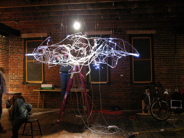
This has been a tough post for me to get around to writing, mainly because I don’t feel I have particularly good pictures of the process or the result, as I was working so intently during the installation that I really didn’t have time to stop and document. But here’s what I have.

Back in November, I made a small edge-lit plexiglass demo as a technology study for a large LED and plastic piece that came to be called “Organic Energy Cloud.” I’ve already written about the design and construction of the LED driver modules; all that remains is the Arduino code and the installation.

Assembly

Lisa Rundstrom installing LEDs on Organic Energy Cloud exhibit

That Friday, while I was connecting all the wires together and working on Arduino code, Lisa was hanging plastic,

A6276 LED driver board, wires, and plastic in Lisa Rundstrom's Organic Energy Cloud

placing LED controllers in it,

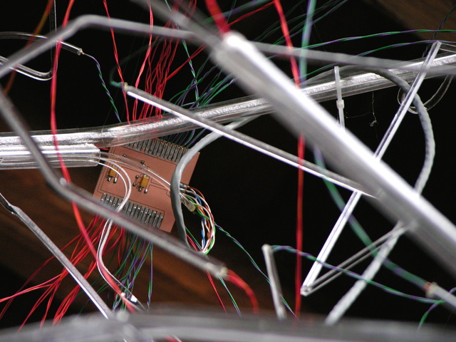
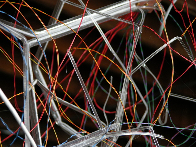
Wires and acrylic in Lisa Rundstrom's Organic Energy Cloud

routing wires, and hot-gluing the SMT LEDs onto the ends and bends of the plastic pieces.

Melty Disaster (Having Nothing to Do with Hot Glue)

I had been programming LED patterns into the Arduino, testing and fixing some bad connections, and occasionally alarming Lisa and her helpers by making everything go dark (Alarmed words from the ladder: “Did I do something???”) or light (“Whoa!, what’s that?”).

About 18:50, ten minutes before the show was scheduled to open, I was running wire from DC motors attached to a couple of bicycle wheels (it was a bicycle-themed show called rEvolve; more on that when we collect all the materials and get the web site up) to the breadboard, and the black jumper wire between the breadboard and the Arduino melted right in front of my face.

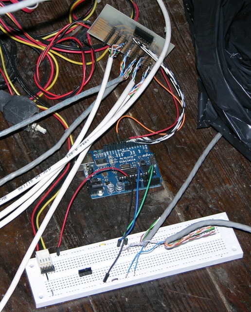
Arduino and Organic Energy Cloud bus/wiring

It turned bright orange, the insulation was dripping off of it, and I couldn’t figure out what tool I might have at hand that I could use to disconnect things without getting burned. It only lasted a second before it melted the wire, too — even had I jumped for the switch on the PC power supply I was using, the circuit would have opened from the wire melting before the power supply’s capacitors had drained.

After discarding the scorched ends of the jumper wire, I looked over the circuit carefully and couldn’t find anything wrong, and I still haven’t figured out what happened. The melted wire was the ground wire connecting the power supply to the Arduino via the breadboard. My wild speculation is that I bumped something that shorted, the wires warmed up and increased their resistance, and the ground wire became the resistor that now dissipated all of the circuit’s energy.

I hooked things back up and with great trepidation (and this time ready to kill power if needed) turned things back on, and they seemed to work. The Arduino booted and resumed its test pattern, the lights came on, etc. But I quickly found that I no longer had connectivity between the iBook and the Arduino.

Since the Arduino appeared to work except for the USB interface, my immediate guess was that the FTDI USB-serial chip had burned out — which turned out to be correct, and which I have since successfully replaced. I had brought another Arduino to use as a backup if anything happened to my first one; but with now five minutes before the official gallery opening, and early arrivals already wandering around, I didn’t feel I had time to swap out the Arduino, program the new one, and be confident everything was going to work.

Fortunately, I had a reasonable program running at the time, which picked a random LED out of the entire piece and then randomly turned it on or off:

  cont = FIRST_BANK + random(LAST_BANK + 1 - FIRST_BANK);
  led = random(32);

  if (random(10) > 3) {
    leds[cont] |= (long) 1 << led;
  } else {
    leds[cont] &= ~ ((long) 1 << led);
  }
  a6276_long(leds[cont]);
  a6276_latch(cont);

If that doesn't make sense, spend a little time thinking about how you would program a nice, random flickering effect with a bunch of LEDs.

Here's the whole program, commented-out test code and all, since even this was still supposed to be test code. That's what we left running all evening.

And the Show Goes On

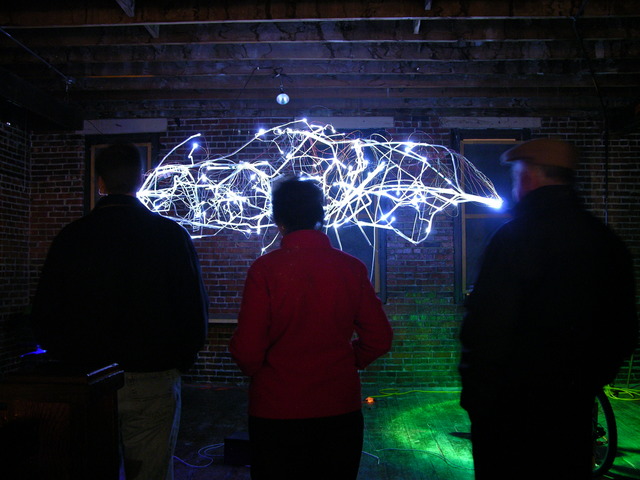
Lisa Rundstrom's Organic Energy Cloud exhibit

Ready or not, the lights go out, the people come in, and the girls at the refreshments table start serving coffee and hot chocolate "with or without something fun in it."

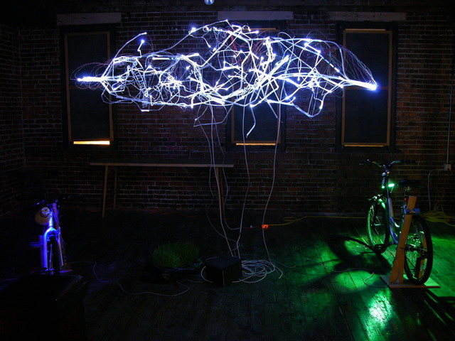
Lisa Rundstrom's Organic Energy Cloud exhibit

This piece deviated far from its original conception, and also ended up not being fully realized due to scheduling and time issues, but it's only fair to show it with the bicycles, even though they no longer made sense as part of the exhibit.

Finally, here's a video of the cloud that was shot by Tom McGuire. Tom had already posted it to YouTube, but I found that the compression had blurred almost all of the detail. He graciously gave me a copy of the raw footage from his camera (which looked fantastic), and between iMovie and Vimeo, I think I managed to keep a little more detail in some of the closeups.

Aftermath

Lisa Rundstrom's Organic Energy Cloud by the light of day

The group opened the gallery for another show on the next Thursday evening when I had to be out of town, and we had to be cleared out of the space by that Saturday morning. Arriving at 06:00 Saturday gave me a chance to take a few more pictures with the space lighted, which show a little more detail of the components of the piece and of the space in which the cloud was installed.

A6276 LED Controllers for “Organic Energy Cloud”

Monday, December 29th, 2008

My earlier edge-lit plexiglass demo was a study for an art/technology collaboration with Lisa Rundstrom that became known as “Organic Energy Cloud,” installed at Diver Studio for the November 28 Final Friday.

Lisa and I ended up agreeing on 200 LEDs (and ultimately installing 160). I had decided early on that I wanted to use two A6276 16-LED drivers to a board, for distributed LED control, all run by an Arduino. Once I got all my parts, over the November 22 weekend, I designed and began assembling the driver boards.

Schematic and Boards

A6276 32-LED driver schematic

The schematic is dead simple — daisy-chained A6276es, common clock and latch lines, output enable tied active (low). For speed and cost, I planned card-edge connectors to solder all the LED and “umbilical” connections to. Although the A6276 doesn’t have separate digital and analog grounds, I used separate wires in the umbilical for digital and LED V+, and I doubled the GND and LED V+ lines for current-carrying capacity.

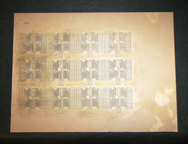
Copper PCB with A6276 LED control boards milled

I hand-etched a prototype PCB to make sure the design worked, but it was pretty time-consuming and not my most beautiful work (especially being a two-sided board). Tom McGuire milled me a much more beautiful set of boards (although not using that mill), and did a very nice job using the drill holes as registration marks to line up the milling for the back side.

Assembly

Monday the 24th, I started pressing my friends into service for slave labor. Jeremy and Mindy were my first victims, and together we got all the PCBs and about half the LEDs assembled. Jeremy was stripping wire ends and Mindy and I were soldering — she did a fantastic job, especially for someone who had never soldered electronics before.

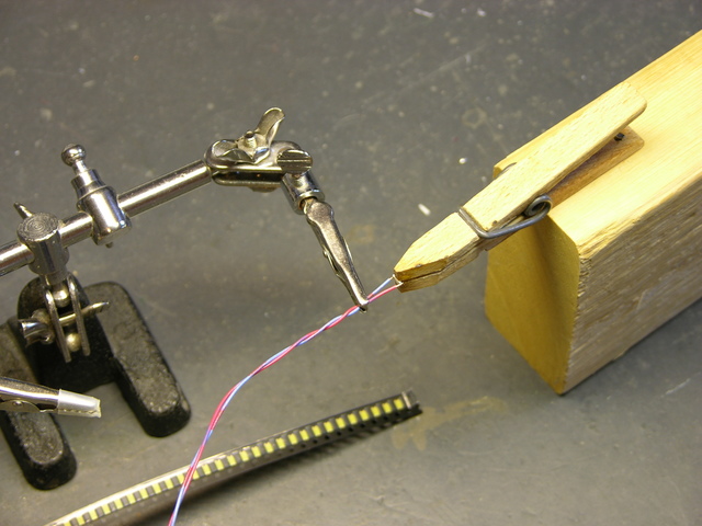
Soldering wires to SMT LEDs with clothespin vise

The key to retaining a shred of sanity while soldering wires onto SMT LEDs is a good soldering jig. Sunday night while assembling my prototype control board, I had tried to assemble LEDs with just the helping hands vise, and the LEDs kept going crooked in the alligator jaws. It took me about an hour to solder sixteen, and I knew that wouldn’t get 200 done in time.

I figured my mom still had some wooden clothespins, and after a little quality time on the disc sander, I had some perfectly elegant, incredibly functional SMT LED soldering jigs. Production speed skyrocketed; frustration plummeted; stabbiness dissipated.

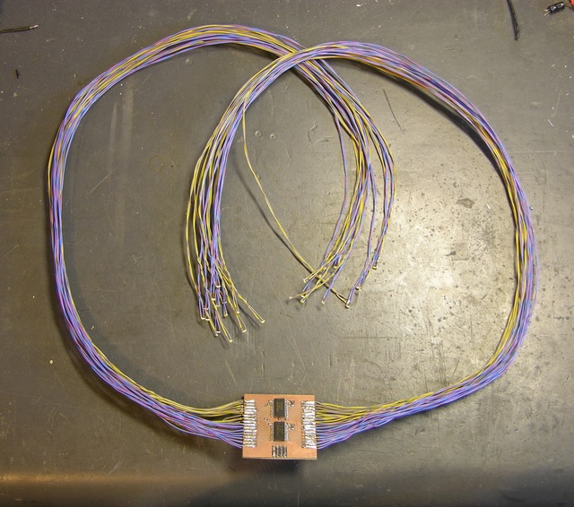
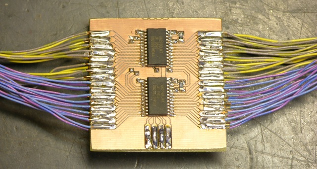
Assembled 32-LED controller

With the LED wires attached, and especially once the umbilicals were on (not shown here), the controllers really reminded me of facehuggers.

Rather than try to size LED wires specifically for LED placement within the piece, we made them all the same length. Lawrence, Gail, and the kids (especially Phill and Jake) stayed up late the next night helping me finish soldering LEDs and assembling the controllers.

Bus

I designed the controllers so that the clock and data lines would run in parallel to every board, but each board would have a separate latch line. It doesn’t matter what’s in the A6276′s internal serial buffer — it only matters when that chip gets its buffer latched to the outputs — and this arrangement made for a minimum of connections to the Arduino.

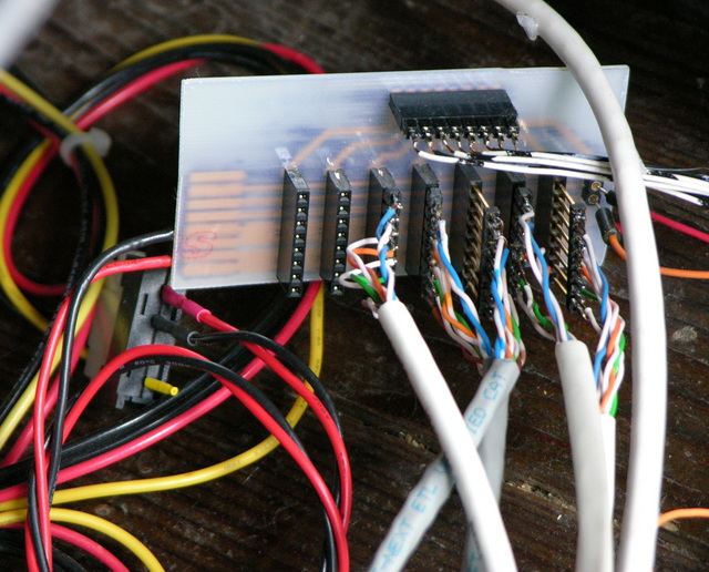
I knew we were going to be plugging and unplugging the umbilicals from the Arduino multiple times before we got everything assembled; but because of the parallel bus arrangement, there were too many wires to plug the umbilicals directly into the Arduino’s headers. I thought about plugging the bus together on a breadboard, but it would have made for a lot of jumper wires for the paralleled lines.

Organic Energy Cloud bus

It ended up feeling easiest to design a small bus board with female headers on it, with the power, data, and clock lines bused, and the latch lines run to a separate 8-pin header at the top. (The bus board could run eight controllers — 256 LEDs — although we only ended up using five controllers.) I would have chosen to use ribbon cable to connect the latch header to the Arduino, except I forgot about that jumper and had to make something quickly out of borrowed wire while we were doing the gallery installation.

All Together

Because I was prepared to run 200 LEDs at ≥ 20mA each, the small power supplies I have weren’t going to be up to the task, and I used a PC power supply, not visible here except for its DC power cables.

Arduino and Organic Energy Cloud bus/wiring

The Arduino is plugged into the bus and the PC power supply, and in the foreground is a breadboard for a part of the project that didn’t come to fruition. This is actually how it sat during the show — Lisa is fascinated by technological infrastructure, and the mess of wires was part of the “organicness” of the piece. More on that in a follow-up post on the installation.

Controller Enhancements

32-LED controller, closeup

Soldering all the LED wires to the card-edge connectors turned out to be a bit of a chore with someone helping with two vises and a needlenose pliers, and incredibly tedious to do alone. All along, I’ve been thinking about how I could design or redesign the controllers so they’d be practical for artists to use without me there to assemble everything, and these boards just aren’t suitable. I have three crucial considerations that weren’t anywhere near met:

  • Wiring the LEDs to the board needs to be easy. (Soldering individual wires was time-consuming and hard to do alone.)
  • Replacement of burned-out LEDs needs to be easy. (Desoldering wires from the controller and resoldering new wires isn’t practical, especially once the board is installed in a piece.)
  • Replacement of burned-out boards needs to be easy. (Desoldering all the wires from a bad board would be a nightmare.)

So ideally I’m looking for a connector that would make it quick and easy to change individual connections on the LED side, and also quick and easy to change a whole batch of connections on the board side — like a daughtercard with an edge connector on the bottom and jacks for LED wires on the top.

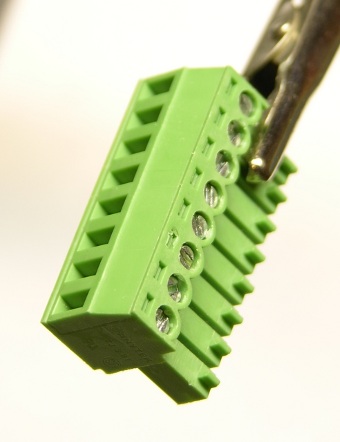
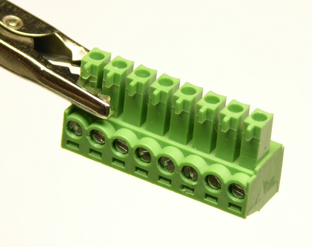
Coincidentally, the week after the show, I was at Anixter’s Chicago facility evaluating replacement keycard door access control systems for work, and I found what looks like the perfect connector on the back side of some HID card readers. The connector has screw terminals on the top for the wires that go to the door strike, motion sensor, etc., and plugs on the bottom to snap the whole thing into the socket on the card reader. The guys from the lab told me they think it’s called a Phoenix or Buchanon connector, and kindly gave me one to take home!

Pluggable terminal strip, top side

Pluggable terminal strip, bottom side

Now I just need to spend some time going through about a hundred pages of the Digi-Key catalog to see whether they carry this, and maybe to see what else they have that’s similar and might be even better.

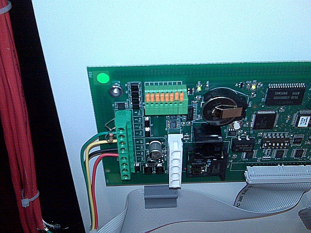
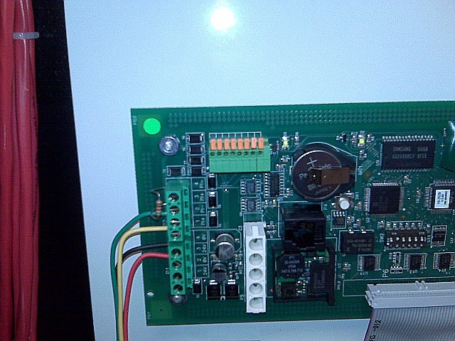
Meanwhile, this past weekend during a scheduled power outage in our computer room for some kill switch and fire suppression work, I found this connector (upper left) inside the fire alarm control panel. (BlackBerry camera + closeup == fuzzzzzzz . . .)

Fire suppression control panel with quick-release wire connectors

Fire suppression control panel with quick-release wire connectors

I really like the orange quick-release levers on this — it’d sure be handy for hooking up the wires in the first place (presuming, as with the screw terminals above, that one is using a large enough gauge of wire that one can clamp them and make good contact). I also love that the wires feed out the top of the connector instead of the side. But it doesn’t offer bulk plug action like the above Phoenix-or-Buchanon connector.

Especially if the two had the same pin spacing, maybe one could offer boards with choice of connector. I think I’d pick the quick-release connector for use in a project with only one or two controllers, and the two-level connector for use in a project with lots of controller boards.

More quality time with Digi-Key for me.

Edge-Lit Plexiglas Demo

Thursday, November 6th, 2008

11-Nov-2008

Welcome, Make and Gizmodo readers! I didn’t expect this kind of attention; but you mention light sabers, I guess geeks like us are bound to get excited. :-)

This was meant to be a crude, quick proof-of-concept prototype, and at that it succeeded. I now have 500 white SMT LEDs on the way from Hong Kong; and when they arrive, they’ll each — grain of rice sized — get glued to the end of a piece of plexi, where they’ll be nearly invisible when off. It’s up to Lisa whether the connecting wires will be visible or minimal; and bless her heart, she says she wants to incorporate visible wires into this piece, so I don’t have to mess with 1000 hair-thin, enamel-coated wires.

Finally, this is only good for artistic purposes or accent lighting. As you may have noticed when shopping for LED light-bulb replacements, there’s very little out there even close to the brightness of incandescents. If you want to light a hallway as you walk through, I’d suggest Piranha (bright) or Luxeon (brighter) LEDs in the baseboards and an ultrasonic rangefinder at the end of the hallway to determine your position.


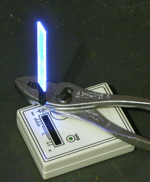
Edge-lit plexiglas strip in LED tester

I have the privilege of working with Lisa Rundstrom on an art installation for a show at the end of November. Lisa does amazing work with plastic (especially acrylic) and light (really, go look at her site), and we’re planning a cloud of 200+ hanging acrylic pieces, edge-lit with white LEDs, interacting with audience members.

If I don’t descend into gibbering madness from the impending deadline, the piece is going to be amazing. (If I do descend into gibbering madness, I expect that’ll be amazing too.)

Our art / technology / education collective has been meeting once a week in preparation for the show, and last night I built a little demo to give a rough idea of what controlled LEDs could look like.

(more…)

First Pictures from Wired 3: Please Wait

Tuesday, April 29th, 2008

Wired 3: Please Wait gallery photo

The videographer’s pictures of Friday’s show are back and the album is available here:

http://picasaweb.google.com/lonnyq/NewAlbum429081230AM

Two notes:

A minor point, the PA system in the corner of some of the pics wasn’t supposed to be there and the projection looked much cleaner without it, but we had trouble with Pd locking up while throwing sound across the network and brought in the separate PA for ambient sound at the last minute (SFX still coming out of the 10-channel system).

And the class is preparing all of the materials from the show and putting them online, so I’ll have a followup post when they’re all available.

Wired 3: Please Wait (Friday Night!)

Wednesday, April 23rd, 2008

I haven’t posted anything in a long time because I’ve been:

  1. Lying on a beach in Jamaica.
  2. Hauling off treasure troves of vintage electronics components from a secret lair off of Highway 77 in northeast Kansas.
  3. Utterly consumed by working with our Technology: Art and Sound by Design students to get our final show ready for Friday night.

You guessed it; it’s option C, which WordPress’s stylesheet renders as 3.

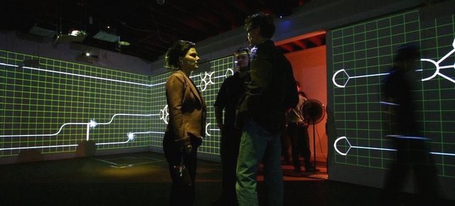
We’re taking over WSU’s Shift Space gallery for April’s Final Friday gallery crawl. We have ten projectors covering the gallery walls in 360° video surround and displaying a giant, abstracted circuit in sections like this:

The student technology projects (abstract LED display, traffic light and control button, computer-controlled archival video footate, floor pressure plates) interface with the “circuit” to control fireball “bits” moving about on the wires and through the gates. Another student has prepared ten-channel audio with both spatially-located sound effects for circuit elements and ambient sound/music to set the tone for the show.

All electronics are done on Arduinos (probably about six in use for the whole exhibit); and PC interfacing, circuit control, and audio are done in Pd.

If you’ll be near Wichita Friday night, I’d love for you to drop by and introduce yourself — ask around for Keith and someone will point you to me.

Shift Space is at 800 E 3rd St N, and we’ll be open Friday night only from 19:00 to 23:00.

Parallax Motion Sensor from Radio Shack

Saturday, January 5th, 2008

The back cover of Servo Magazine is always an ad from Parallax, and the December issue featured several sensors that will now be distributed through Radio Shack, including a motion sensor for $10.

John and I are getting ready for this spring’s Technology: Art and Sound by Design class; and although I think John will be doing most of the teaching this year, I’m always on the lookout for sensors that would be good for students’ interactive sculptures.

Jason at work suggested that the LED puck could have a motion-sensing mode, to serve as a sort of intrusion alarm.

When two separate events occur simultaneously pertaining to the same object of inquiry, we must always pay strict attention. Or, ah, three events.
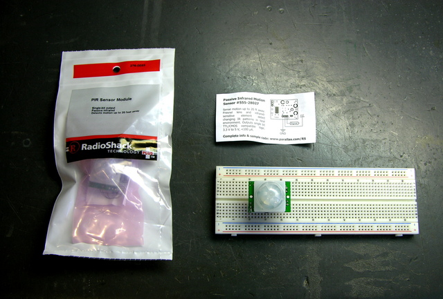
Two Parallax / Radio Shack motion sensor kits

I picked up a couple of the sensors last week to try out. The clerk said when they got them, he had thought they’d never sell any. Why am I always the guy buying the weird stuff?

How Motion Sensors Work

The heart of common motion detectors is a pyroelectric sensor, which is essentially a FET with a window in the case opening onto an infrared-sensitive gate. Changes in the level of IR light with a wavelength corresponding to body heat cause changes in the drain-source resistance, which the circuit monitors.
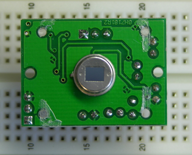
Parallax pyroelectric sensor

The real trick is that the sensor is then placed behind a multifaceted lens that (loosely speaking) “chops up” the view of the world into smaller cones of heightened visibility and intervening areas of lessened visibility. Think of a stage polka-dotted with multiple spotlights, only actually seeing that way rather than merely illuminating that way.

A body moving from an area of reduced visibility into an area of increased visibility causes a rapid change in the amount of IR (body heat) shining on the sensor, hence a rapid change in its drain-source resistance. The motion detector circuit watches for these rapid changes, and when detected, triggers the alarm. This is why Robert Redford has to move slowly while retrieving the MacGuffin from Cosmo’s office in Sneakers.

A brief note about the multifaceted lens: It is usually a Fresnel lens, but being a Fresnel lens is a red herring. That simply makes the lens thin and easy to mold out of plastic; it is really the multifaceted nature of the lens that’s important. Closer examination of a motion sensor lens easily reveals that it comprises multiple adjacent Fresnel lenses.

The Fresnel dome of this sensor, by the way, is too large to fit into the LED puck (as, most likely, is the PCB). However, it’s not out of the question to purchase a separate PIR element and mill a multifaceted lens pattern into the puck enclosure above it. It would be an interesting challenge, perhaps for a later version.

The Parallax Sensor

The sensor comes with an absolutely minimal connection diagram, and refers to the Parallax web site for full documentation. The module has a three-pin connector (bottom) for ground/V+/output, and a two-position jumper (upper left) for retriggering mode.
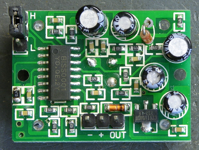
Parallax motion sensor, component side

The power/output header is annoyingly the same height as the other components on the back side of the board, so the sensor cannot be plugged directly into a breadboard for prototyping; it requires an extension. Parallax recommends a servo extension cable; I soldered a three-pin header to a three-pin header socket to make a rigid extension for breadboarding.

The module’s output is active-high. The Parallax documentation indicates that the jumper selects retriggering mode. With the jumper in the L position, the module triggers the output upon detecting motion and then goes low again. With the jumper in the H position, the module is supposed to keep the output high as long as motion continues, but mine does not.

The datasheet indicates that the module needs a “warmup” period of about a minute, during which time it’s adapting to ambient conditions and may trigger randomly. My experience was similar, so anyone using this module needs to be prepared to accept random triggering for a while after startup.

The package and datasheet indicate a detection range of about 20′. I didn’t have room to test this, but I’m willing to believe it until I learn otherwise. Apart from the minor annoyances above, the sensor really is very easy to use, particularly for our class. It seems quite responsive to motion, and certainly responsive enough to pick up gallery visitors not specifically trying to sneak up on it. Output is a very clean 5V, so it’ll be easy for students to interface to the Arduino.

Sensitivity is fixed. It’d be nice to have a trim pot to adjust sensitivity/range, particularly for use in interactive sculpture projects. A Halloween prop-maker going by the name “Scary Terry” has written a nice review of the motion sensor, and includes pictures of mounting it inside PVC pipe to control its angle of sensitivity. I guess with care, the sensor could be angled toward the ground in such a way that it would be triggered only when feet entered a designated area.

Hacking the Sensor

I suspect that most students using this sensor either would trigger a long sequence of actions when motion is first detected, or would like to get a continuous (retriggered) signal the entire time motion is detected. I’m somewhat interested, though, in a much finer-grained notion of “the entire time motion is detected” than that.

By my rough count, the sensor triggers for about two and a half seconds each time it detects motion. It then locks out briefly (didn’t time it — say another couple of seconds?) during which time it’s insensitive before it can detect motion again.

I’d like to be able to get a series of much shorter spikes and much shorter recovery time. I don’t know exactly why; it just seems useful to me.

Let’s go back to that component view:

Parallax motion sensor, component side

The IC doing all the work is a BISS0001. The only datasheet I can find for it is in Chinese, yay, don’t read that, sorry. The chip has a bunch of comparators, some logic, a logic section labelled in Chinese, and two timers labelled in Chinese. It looks like it’s probably made specifically for motion-sensing applications.

Fortunately the pinouts and component values are labelled in English, so I was able to make enough sense of the datasheet to understand how to set the timing constants. From the sample application circuit, pin 2 is obviously the master output; and on the pinouts, pin 2 is labelled VO.

On the timing diagrams, VO goes high for a period labelled TX and low for a period labelled Ti. Just above that, we have the equation TX ≈ 49152R1C1 leaping out at me from a wad of impenetrable Chinese. On the functional diagram, R1 and C1 stack from pin 3 to 4 to ground.
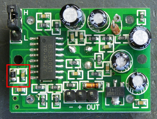
Parallax motion sensor, pulse timing components

Okay! On the PCB, pin 3 goes to a resistor that said “204.” (Ignore the 473 in the picture.) The resistor and the IC’s pin 4 go to a capacitor, which goes to ground. We’re in business!

The resistor is labelled as a 200KΩ, and my meter confirms that. The capacitor is unlabelled; in-circuit, my meter tests it at about 470pF. Doing the math:

49152 R1 C1 = 49152 * 200KΩ * 470pF ≈ 4.6 seconds

Hm, that’s a little off from the 2.6 seconds I was counting, but same order of magnitude. For a capacitor value that small, I’m willing to believe that I’m getting extra capacitance from my meter probes and from measuring it in-circuit. I think we’re in the ballpark.

The easiest way to shorten the on-period (TX) seems to me to be replacing the resistor. To take the period down an order of magnitude, I should use about a 20KΩ resistor. After looking at the SMT resistors on a dead PC motherboard, I found a 473 (47KΩ) and figured it was enough smaller to make my point.

I desoldered it by wrapping a piece of heavier wire around it and heating the wire, like Josh suggested, and it worked great. Then out of laziness and because the new resistor was larger than the existing resistor and might not fit the pads well, I just soldered it on top of the resistor that was already there, in parallel. Makes it a 38KΩ resistor instead of a 47KΩ, so we’re even going in the right direction.

I powered up the motion sensor again, waited a minute for it to settle down, and started timing its response. On-time after sensing motion (TX) is now in the half-second range. The absolute numbers still don’t match what the equation says I should get, but the relative values are right on — a resistor with 1/5 the value reduced TX to 1/5 of its former value.
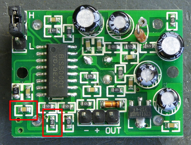
Parallax motion sensor, lockout timing components

Pretty slick! Now I can pick whatever TX I want, be it short or long. I haven’t tried it yet, but the lockout time between motion detection (Ti) is set by R2 and C2 on pins 5 and 6, and they’re easily accessible as well, so I should be able to change that too.

And About that Datasheet . . .

Don’t get me wrong about the Chinese datasheet. Sure I would have been disappointed if I couldn’t read it, but I was actually really pleased that sections of it were in English. I’m aware that people throughout the rest of the world have to learn English in order to do a lot of technical things, and do so with ease and proficiency much greater than that of the few Americans who bother to learn languages other than English.

Bunnie Huang has an interesting blog post that touches in passing on certain types of devices using chips of Chinese manufacture that can’t be found, or can scarcely be found, by searching Google in English:

Just try searching for USB mass storage controller ASICs, or digital picture frame SoCs on Google in English, and then go and open up one of these devices and compare your findings. I bet you’ll find that the chips most frequently used in these popular devices are best searched for in Chinese.

It’s a competitive world out there, and those of us in the west have had it awfully easy for an awfully long time. I know as a mere hobbyist, the technology I use is far behind the leading edge, and I’m not yet impacted in nearly the way of engineers developing new products for market. But the world is changing, no doubt about it, and I hope it’s a while yet before it impacts my ability to tinker.