The fan in the network switch in my home office is too loud. It’s the loudest thing in the whole room — louder than my newish and very quiet Dell PC. (Fedora, installed before ever booting the preinstalled XP Home, in case you wondered.)
I’d rather not have a switch there at all, but the DSL comes in on the ground floor (where my office is), I’ve tucked my server down in the basement, and I haven’t installed structured cabling yet. (The house is a hundred years old and the crawlspace is . . . interesting.) I need more connections going back and forth than I have cables, which means using a switch.
The Cisco switch I was using had only 100M ports, but my workstation and server both have integrated gig ethernet, so I was looking to upgrade the switch anyway.
I recently bought an old Linksys GigaSwitch EG0008 on eBay. It’s a 1U rack case with only eight gig ports on it — pretty much an antiquated beast. I was hoping it’d use passive cooling or at least have a quieter fan than my Cisco 1924.(*) Boy, was I wrong.
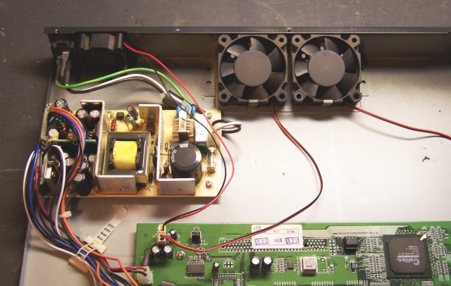
The Linksys has three fans, each loud. Two are in the center of the back, and there’s a separate one by the power supply. I took a little time yesterday to try to quiet it down.
Before
I used my sound level meter (an older version of this Radio Shack meter) to measure how loud each fan was. This was a very informal test intended just to give me a general idea; and due to the range of the meter, I measured from about 10cm away instead of the standard 1m.
I unplugged two fans at a time so I could test each fan individually. The small fan in the corner was the loudest, at about 58dB. Each of the two larger fans in the back registered about 57dB. With all of them running, I got about 62dB total.
Fan Changes
The first step was simply unplugging the two larger fans in the back. In an unventilated wiring closet, or stacked in a rack with other hot equipment, I’d want all the forced air I could get through this thing. But sitting in my office on a small stand under the base of my LCD monitor, it’s not going to get very warm. It probably doesn’t need any fans there, and one should certainly be enough.
With only the small fan plugged it, the volume dropped to slightly louder than my Cisco. Not good enough.
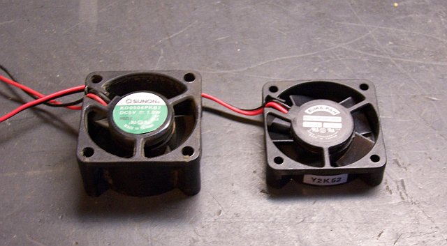
The small fan sounded a little rough to me, so I peeled back the sticker and added a drop of oil to its axle. It smoothed out a bit, but still not good enough.
I had another 40mm fan on hand that I bought last year from All Electronics, so I soldered a connector onto it and hooked it up to the power. Sitting out in the open, I measured it around 54dB, so it seemed to be an improvement.
The original fan wasn’t mounted with screws or bolts, but rather by snapping into position. With the replacement fan being so much slimmer, it no longer fit the slot. Since this isn’t for a ruggedized mobile application where things bounce around a lot, I just stuck it in place with hot glue.
Once in place, it measured about 58dB — the same as the original fan. Grrr.
Vent Holes
I noticed two differences in the sound of the replacement fan between when it was sitting in the open and when it was mounted in the case. The case acted as a sounding board to amplify the fan’s noise; and there was considerable wind noise when the fan was in position. I didn’t really have room to isolate the fan from the case with rubber strips, but I did tackle the wind noise.
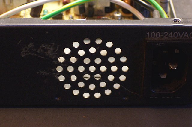
The ventilation holes behind the fan were not exactly what I’d call generously sized. I used my stepped drill bit to enlarge all of the holes that were in line with the fan’s blades.
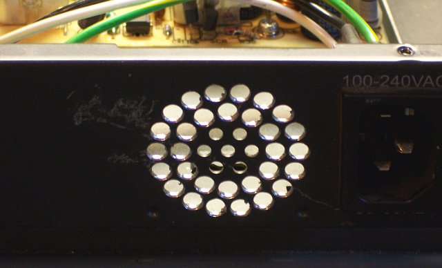
After reinstalling the new fan, the overall noise level dropped to 54dB, a slight improvement over the first installation of the new fan and a considerable improvement over the original equipment.
I reassembled the switch and swapped it into service in my office, and it seems to be about as loud as the Cisco was. Interestingly, the pitch of the noise is a little different, so I notice it each time I step in the doorway. I’ll get used to it soon enough.
Closing Thoughts
In retrospect, since both the original and replacement 40mm fans measured about 58dB when mounted in the case before enlarging the vent holes, I could probably put the original fan back in and have approximately the same sound level improvement.
I’d like to find a quieter fan, though. I know there’s a whole market for PC case mods with really, really quiet fans. I’ll ask around and see whether anyone I know has a tested source. So rather than go back in to reinstall the original fan, I’ll hold out for a yet-quieter replacement.
Footnote
* Yes, I know the Cisco 1924 is a 10M switch. My 1924s have two 100M ports commonly used as uplinks; so at each end, one of the ports is the uplink and the other connects to the fast computer. The DSL firewall only gets a 10M port, which is faster than its WAN side anyway.
