I’m working on a control system for my stereo, with more information on that project to be posted soon. I was running into a problem having enough pins on my PIC to connect all the inputs, pushbuttons, LEDs, and outputs.
Yesterday I was talking to Tom and describing how each bicolor output LED requires two microcontroller pins to control both colors. I’m sure this scheme has been used a million times before, and I may even have seen it before, but I was very pleased to realize in a flash of insight how to drive a bicolor LED from a single output pin.
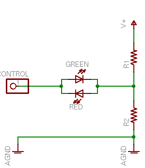
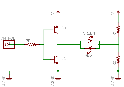
Instead of connecting the LED between the control pin and V+ or ground, connect it to a voltage divider between the two. Raise the control voltage to V+ and the green LED will conduct through R2. Lower the control voltage to 0V and the red LED will conduct through R1. Here’s the best part — change the control pin to an input and it’ll go into a tristate (high-impedance) mode, leaving the left end of the bicolor LED floating, with both elements off. Perfect! That saves my project!
I breadboarded this circuit with 330Ω resistors, and the LED was quite a bit dimmer than normal. Well, of course it was; it’s running off less voltage than usual. Plus the voltage divider isn’t exactly a stiff current source. But I was curious exactly how much less voltage (seems obvious, but wouldn’t it be nice to know for sure?), and what was the exact series resistance (ah, somewhat less obvious, eh?).
Thévenin Analysis
Thévenin’s Theorem states that any linear circuit (comprising only voltage sources and resistors) can be represented as a single voltage source and a single series resistor, and provides a very simple method to determine the equivalent voltage and resistance. So a Thévenin analysis of the voltage divider will give us a simpler model of that section of the circuit, which can then be used to determine the actual LED current.
First, to determine the Thévenin voltage (VTH), mentally remove the load from the circuit and use Kirchhoff’s Law to find the voltage at the load connection.
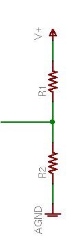
In this case, assuming R1 = R2, VTH is V+ / 2.
Next, to determine the Thévenin resistance (RTH), (mentally) short out all the voltage sources and use Kirchhoff to find the overall resistance looking into the circuit.
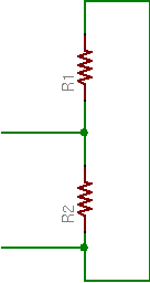
In this case, mentally shorting V+ to ground puts R1 and R2 in parallel, giving
RTH = (R1 * R2) / (R1 + R2)
Or again in the case where R1 = R2,
RTH = R2 / 2R = R / 2
Thévenin Equivalent Circuit
So assuming R1 = R2, the voltage divider is equivalent to a voltage source of V+ / 2 in series with a resistance of R / 2, which gives this simplified circuit:
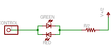
This makes it easy to determine the LED current (ID). Whether the control voltage is at V+ or 0V, the LED and Thévenin resistor will see a voltage of V+ / 2 (forward or reverse).
Using the zeroeth approximation of a diode as a device that conducts electricity in a forward direction with no voltage drop, the resistor has the full voltage across it, so the resistor current
IR = (V+ / 2) / (R / 2) = V / R
and ID = IR. For a 5V supply and 330Ω resistors, I = 5V / 330Ω ≈ 15mA.
But that’s exactly the same current (and concomitant LED brightness) we’d expect running an LED from a full V+ with a full R, and I distinctly noted that the LED was dimmer. What’s going on?
LED Voltage Drop
The answer lies in the first approximation of an LED as a device that conducts electricity in the forward direction with a voltage drop and no resistance. The bicolor LED I was using has about a 2V drop in either direction (about 2.08V green and 1.95V red, at the temperature and moment I measured).
Still using a 5V supply and 330Ω resistors, an LED voltage drop VD = 2V gives a voltage across the resistor of
VR = (V / 2) – 2V = 2.5V – 2V = .5V
IR = VR / RTH = .5V / 165Ω ≈ 3mA
ID = IR ≈ 3mA
Whoa! That’s a whole different story! Halving the effective supply voltage dramatically exaggerates the effect of the LED’s voltage drop.
In fact, to get back up to ID = 15mA:
RTH = VR / IR = .5V / 15mA &symp; 33Ω
That’s an order of magnitude lower current-limiting resistance to get the same LED current and brightness.
Even worse, note that this circuit (the original) has a continual current of V+ / 2R through the voltage divider. With 330Ω resistors, that’s 7.6mA (38mW), which may be tolerable in a non-battery-driven circuit; but with 33Ω resistors, that’s an unacceptable 76mA (380mW) per LED driver!
Tolerable Adaptations
So how can we make this circuit work well enough to be practical? Here are a couple of options.
First, note that the current-limiting resistance needed to be made so low because half the supply voltage is barely more than the diode’s voltage drop. With a higher supply voltage, more voltage would be “left” after taking out the LED’s drop, and a higher resistance could be used to get the same LED current.
But how far can we raise the supply voltage? For the circuit to work properly, the control voltage from the microcontroller needs to swing over the same range as the LED’s voltage divider. And alas, the PIC I’m using has a maximum VDD of 7.5V; or say a safe working voltage of 7V.
Adding 2V to V+ adds only 1V to the LED/resistor supply, increasing VR from .5V to 1.5V, or threefold. That translates into three times larger resistance and one third the voltage-divider power consumption — progress, but not as much as I’d like.
Second, note that the bicolor LED I’m using is not particularly high performance. Newer LEDs appear to me to be several orders of magnitude brighter at the same current. (Go check the amazing mCd claims of LED vendors on eBay. For the most part, they’re increasing efficiency, not current-handling capacity.) I’d gladly pay a little more for a much brighter LED that has lower current requirements for the same brightness.
Even one order of magnitude difference in LED efficiency pushes the voltage divider power consumption back into an acceptable level for the device I’m designing. It also cuts the power requirements for the PIC pin driving the LED. The datasheet quotes 25mA source or sink per pin, 200mA source or sink for all pins, but I’m old-fashioned and don’t want to push my luck.
One thing I don’t know is whether high-efficiency LEDs have the same voltage drop as traditional ones. With only 2.5V available for the LED, if higher efficiency comes at the expense of a higher voltage drop, I could “efficient” the circuit right out of its operating range.
Boosting the Drive Current
Before doing the actual calculations, I was pondering whether the PIC could really source and sink enough current to power all my LEDs as brightly as I want. I was musing out loud with Tom about how to build a transistor driver to buffer/boost the PIC’s output.
The driver needs to be a totem pole, meaning that it has two stacked elements so it can source the LED line up to V+ or sink it down to ground. The catch is the tristate trick that makes it possible to turn the bicolor LED off. Trying to cram a traditional complementary totem-pole output into this circuit IS WRONG AND DOESN’T WORK.
When the control line is high, the upper (PNP) transistor is off and the lower (NPN) is on, so the NPN pulls the driver output low. Likewise, a low control line pulls the driver output high.
The problem is when the control line is tristated. Then current flows through the PNP’s emitter and base to the NPN’s base and emitter, turning both transistors on and shorting V+ to ground. Real totem-pole drivers are designed to make sure this can never happen, even during transitions.
Here’s Tom’s solution, which like the tristate trick is probably a reinvention, but which is so clever that it still tickles me a day later to think about it.
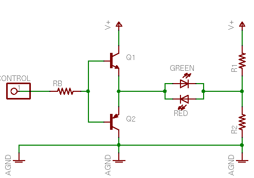
Just swap the NPN and PNP transistors in the totem pole, putting the NPN on top and the PNP on the bottom. When the control line goes high, the upper (NPN) transistor is on and the lower (PNP) off, so the NPN pulls the driver output high. Likewise, a low control line pulls the driver output low.
And a tristated control line leaves both transistors off and the driver output in a high-impedance state, because the emitters aren’t connected to the power rails to conduct through the bases any more.
Brilliant! Makes me want to use it, even though I realize with high-efficiency LEDs I no longer have any technical reason to. ![]() But I’ll keep it in my bag of tricks.
But I’ll keep it in my bag of tricks.
Just a note on tristating a CMOS pin:
tristating or setting a controller pin as input, and leave it floating or (even worse) setting it to Vcc/2 is a reliable way to destroy the input gate. To avoid this you must take care that a pull-up or pull-down exists on the input which pulls the gate to a CMOS-defined ’1′ or ’0′ level. Well I guess most of the AVRs and PICs out there have internal pull resistors there, but its not a general rule.
Now that you’ve solved the 1-controller-pin-controlling-2-LEDs problem you might want to read about charlieplexing, a way to drive n^2-n LEDs using n pins. That means impressing 20 LEDs can be controlled by 5 IO pins.
http://en.wikipedia.org/wiki/Charlieplexing has a good linklist.
m
Great idea, now I know what to do if I run out of pins.
Couldn’t you just get bi-colour LEDs with a forward voltage of 2.5 or more volts? That way, no resistor is required to run them, and you could use really minimal values for the divider.
Alternatively, how about using a zener diode to limit the voltage?
Mojo, unless I misunderstand what you’re suggesting, using LEDs with a higher voltage drop makes the problem worse because increasing VD decreases VR, forcing you to decrease R to maintain the same IR and ID.
Hi,
I just breadboarded this circuit and it doesn’t work that well. I messed around with different values to get it to work somewhat. When I dropped the resistors in the voltage divider down to about 100 ohms each or so, I could see the LED’s barely lighting up, but not enough to be usable. I used a 2n3904 for the npn and a 2n4403 for the pnp. Since the latter circuit has the two transistors in emitter-follower configurations, I removed the base resistor and got it to work better, but then the LED’s glowed a little bit in tristate mode. If anyone gets this to work right, please let me know!
Thanks
This article: http://www.edn.com/article/CA6262537.html
gives three different techniques to drive a bicolor LED from a single output pin. #1 is to use an external inverter gate, #2 is essentially your solution with the addition of two zener diodes, and #3 gives a circuit using transistors to drive the LEDs.
Can you explain what the diodes are for? I’m just a beginner at this stuff. My guess is to reduce the current loss through the voltage divider and to control the LED voltage in both red and green states, although I’m not sure why you couldn’t just use appropriate resistor values to do that.
Okay, I’ve thought about it more, and I think I understand what technique #2 from that article is doing. It adds two zener diodes in between the two resistors of the voltage divider. If you select diodes with appropriate Zener voltages (> V+/2 but < V+ – VLED), you should get no current loss through the divider at all. At 5V, that doesn’t leave you much voltage to play with, but you can use as small a resistor as needed to get the current you want without worrying about losses. All the current flows through the LED.
Jin, I had looked at the circuits when you posted, but hadn’t completely figured them out yet. I’m glad you had time to go through them some more.
That’s a good analysis of the Zener circuit! A couple things to beware of:
Hello!
An excellent idea. But what about using either a SN74125 (Or SN74LS125) or a SN74126 (Or SN74S126) to drive the device?
And that’s the circuit guide I am trying to find. I know the LED gets placed between two buffers and the way the enable lines are driven causes the right colors to be seen. It’s how to drive them that’s causing me to be something of a frustration experience specialist.
Gregg, that’s an inverting buffer, right? The article I linked to above had a circuit that used an inverter. Sadly, it no longer appears to be available. I think you can do what you want by having your pin drive the input of an inverter and hooking up the LED (in series with a current limiting resistor) in parallel to the input and output of the inverter. When the pin goes high, the inverter output goes low and current flows one way. When the pin goes low, the inverter output goes high and current flows the other way. There is no way to turn it off in this manner. This assumes your pin can supply enough current for your LED, otherwise you will have to add a non-inverting buffer or transistor to supply the current.
I would recommend using a circuit similar to the one Keith outlined above. Here is an example:
http://dl.dropbox.com/u/3845046/intervalometer.png
The LED driver is the lower half of the diagram. The voltage drop of the LED plus one of the zener diodes must be less than VCC. (The LED in the diagram is intended to be a bicolor LED of the “back to back” sort.)
You can also use a rail splitter chip instead of the resistor divider in Keith’s last circuit, which gives you the same circuit but with much less wasted current.
Jin, I didn’t know there was such a thing as a rail splitter IC. Very nice! Thanks for the education!
I believe I did. As for part availability, I believe that it might be from one of three suppliers here in the US. But I am not sure which ones.
Not really about polarity, the SN74125 and SN74126, are the same quad tri-state buffer, but the line that sets the ability of the buffer is the difference. the SN74125 is inverted, and the SN74126 isn’t.
I’ve also used two buffers of six on a SN74367 to do the same thing. In fact that’s my next step. To use the six of that chip to drive three LED units.
Hello,
I downloaded this “one bit – two LED” schematic and description a couple years back because I thought it might be useful one day, but I have completely forgotten where I got it from or whose work it is. Maybe someone else interested can google it and find out. It is certainly NOT my work, so I don’t claim credit, nor can I comment on it or answer any questions. I just thought it might be helpful for this thread. The text is below the dashed line. Here is a link to the schematic. I don’t have any web space, so I stuck it on my yahoo photos page:
http://pulse.yahoo.com/_ZOQB4FGXO5ZH752O73MPYLXG2Y/album/photos/316026/in/430449
Good luck,
James
———————–
Using discrete components, another circuit offers an inexpensive approach that avoids the other circuits’ disadvantages (see diagram). When the microcontroller’s output port goes high, current flows through the green (upper) LED, R2, D2, and FET Q2, which the port’s high level turns on. When the microcontroller’s output port goes low, transistor Q1 turns on and delivers current to the port pin through R2 and the red (lower) LED. The circuit operates symmetrically because silicon diode D2′s forward-voltage drop is present regardless of whether the microcontroller’s port pin goes high or low. VCC may vary during operation but must remain higher than 3V.
You can individually adjust the LEDs’ currents to equalize brightness or compensate for a difference between the microcontroller’s power-supply voltage and the LED-driver circuit’s VCC. Replace R2 with two resistors connected in series between Q1′s emitter and D2′s anode. Connect the midpoint of the two resistors to the LEDs.
With the microcontroller’s port pin configured as an “input with pullup,” the port delivers a small current to the green LED. However, pullup-resistor values of 22 kO or higher do not cause misleading light output from LEDs in the off-state. When the input signal from the port pin floats—that is, with VCC at 5V and the port configured as an input with no pullup resistor—the circuit draws no additional current, and the quiescent current, which R1 determines, averages less than 100 µA.
Oh yea, I forgot to say that the main advantage of this circuit is that it allows one output pin to give give a three-state output. That is, the one bit can operate either of the two LED’s but can also turn them both off by setting the output to Hi-Z (floating). Pretty cool, huh?
BTW, when I breadboarded it, I used a bipolar instead of the MOSFET and it worked fine. I was easily able to EITHER turn on the green LED, turn on the red LED, or turn them both off, with just one output pin (provided the output pin could be set to Hi-Z, which almost any MCU can do these days). However, as I’m not the author, I can’t answer any other questions.
Good luck!