I recently bought an ancient Sony “LCD Data Projector VPL-351Q” (video projector) on eBay for a reasonably modest price, without realizing just how ancient (and huge) it was. Fortunately, I was shopping geographically and was able to pick it up in person; it would have cost me a fortune to ship.
I’m interested in setting up a projector in the family room for watching movies, and this was a very affordable way to experiment before committing to an expensive course of action.

That’s my 19″ stereo cabinet this thing is sitting on, with candlesticks elevating the front feet. It’s immense.
Old Lamp (Bulb)
Each time I power up the projector, it tells me that its lamp is old and needs to be replaced soon, which is no great surprise. (The onset of a lamp replacement warning seems to be a pretty strong motivator to retire projectors that are getting old anyway.) Of course, the few vendors I can find selling replacement lamps want $500 and up for them — a healthy order of magnitude more than I paid for the projector. Ha ha. This lamp is a bit dim, but not $500 dim.
I’m very curious how the projector knows the lamp is old — by counting hours of use (with a timer that I could reset?), or by monitoring lamp current. I’m also intrigued by the idea of rebuilding the lamp using something else — an automotive halogen bulb, perhaps. I assume I’d need to reuse the same reflector, and I think I might be able to manage it.
I’d also have to rig a different power supply for the replacement bulb — the original appears to run on 70V. The real problem would be if the projector monitors the bulb voltage or current (that I was no longer using) and shuts down if it seems improper. I’m not sure I’d be willing to go to the effort to rework or disable such a circuit.
Green Lines
Worse than the brightness, though, is a pair of green lines across the screen, just below the middle of the display. When I got it home and discovered them, I popped the case to have a look and found that the projector has a beam splitter, three monochrome LCD screens with color gels, and a beam . . . uh . . . unsplitter. So it’s plausible that the problem is isolated to the green LCD, and perhaps is nothing more than something is wrong with a row control line.
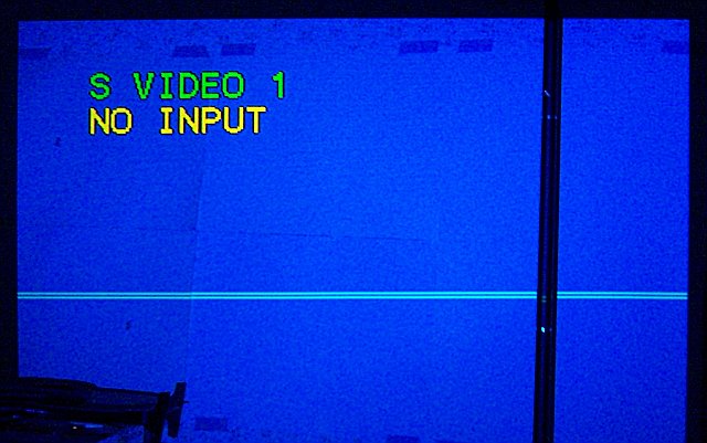
The black line, BTW, is a halogen torchiere — I’m temporarily projecting this onto the wall behind the couch. We’ll rearrange the furniture if it works out.
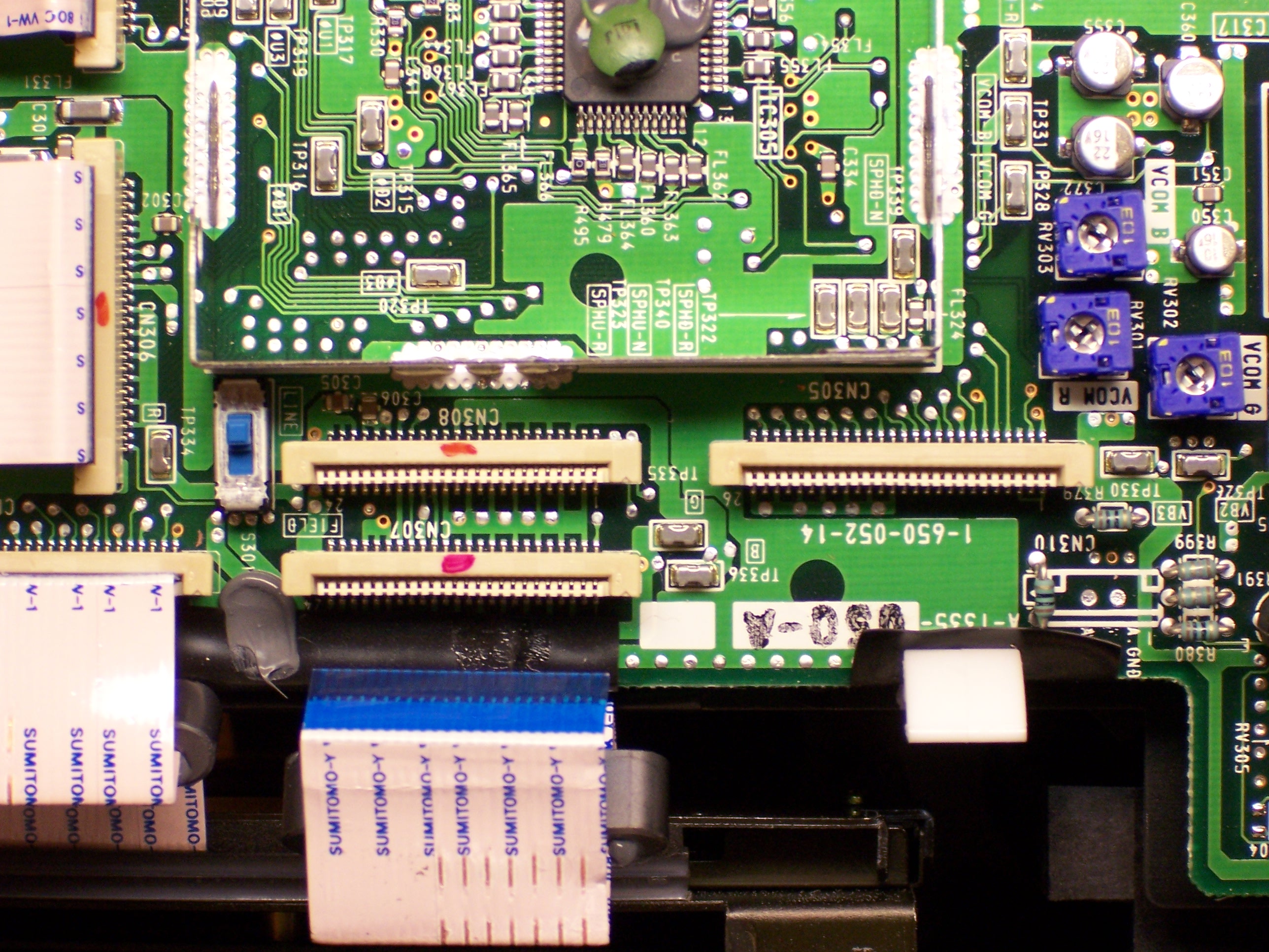
Inside the case, each LCD has two flex-PCB cables, presumably for row and column select. If the silk-screened labels are to be believed, the connectors in the upper center and right of the picture control the blue LCD, the lower center and left control green, and the one on the left plus the one disappearing off the upper left control red.
LCDs with which I’m familiar are clear when idle, and opaque when active. (Think of an LCD calculator or monochrome PDA — they’re grey when they’re off, not black.) If that’s how these LCDs work, then the bright green lines are rows that are letting green light through all the time — rows that are transparent all the time — rows that are never getting activated. Maybe I just had a bad connection on a pin or two.
(The connectors don’t have nearly as many pins as the horizontal and vertical resolution of the LCD, so my hypothesis isn’t perfect. A one-to-one match between control lines and rows would make a pretty compelling case. But even with row multiplexing or addressing, a single address line could still impact only one or two lines. Mmmmm . . . okay, not really; at least not two that close together. But bear with me.)
So the first thing I did was pull the cables for the green LCD, clean their contacts, and reassemble. Alas, no change.
Cold Solder?
Still chasing the notion of a bad connection, I wondered whether one of the ribbon sockets might have a bad solder joint. Logically it should be the green row controller; and since the LCD has lower vertical resolution than horizontal, that means it should be the smaller of the two green connectors — the one in the lower left.
Tonight I put the SMT tip on my soldering iron and went to reheat the solder job on the green connectors — on both green connectors, for good measure. I did reheat them — I made some nice solder bridges, and I think lifted a trace or two. When I tested the projector again, I had every seventh blue column missing (I had absent-mindedly touched up the wider blue connector also — so wide == columns), and some other strange artifacts.
Not yet deterred, I reheated the solder joints again. This time, though, I used the heat gun to do a more consistent job. I was concerned that the sockets were plastic and would melt before the solder reflowed; but I kept a close eye on them, and although they got a bit darker, they didn’t melt a bit. I knew I got the solder to reflow because the SMT slide switch actually tipped over sideways from the airflow at one point, then popped itself back up when I backed away.
The heat gun was the right approach and surface tension is my friend, because that treatment fixed the ills I had just caused. The projector is now back to two horizontal green lines.
What Next?
I’m curious how the ribbon cables attach to the LCDs. It still seems plausible that I have a bad connection somewhere, and perhaps that bad connection is at the green LCD itself. LCD elements that I’ve played with don’t have wire connections — everything on the glass is next to invisible, as if it’s painted on with disappearing ink. Connections are made by pressing metal or anisotropic rubber contacts against the traces on the glass — maybe one of those connections needs cleaning?
I’m willing to dig in and examine the LCDs, but I’m leery of unmounting them. They’re obviously positioned very precisely to get the three screens’ pixels to align on the output, and I haven’t looked closely enough yet to see how that alignment is done. I’ll want to be sure that I can get the screens realigned properly before I consider unmounting one to examine its connectors.
If the problem isn’t the green screen itself, then likely a driver chip is bad, or has a bad connection. I’ll get there eventually.
This might seem like a dumb question, seeing as how I am not too sure how the LCD’s connect to the projector, but is it possible for you to plug the LCD’s into different slots? If it is then you could determine which is at fault the LCD or the motherboard; by plugging a red LCD into the green LCD’s conection. If you have red lines across the screen then the foult is with the motherboard if you still have green lines across the screen then the fault lies with the green lcd screen.
I don’t know if this is relevent but, my laptop had a similar problem with a lcd screen, (it moved up and down, and ‘flickered’). I fixed the problem by working on the connection b/w the ribbon and the lcd screen.
Good Luck hope this helps let me know
Welcome, Lev!
That’s not a dumb question at all; I’d normally have tried that immediately. Unfortunately, the ribbon cables are custom length and custom bends for where they’re supposed to go, so I can’t readily swap them.
In some further experimentation that I haven’t posted yet, I determined that the problem is where the driver ribbons connect to the glass. Inside each LCD frame are several (eight? don’t remember) driver chips “floating” in the middle of the flex-PC ribbon. Their output goes to “pins” that are (were) glued down to the glass.
I lifted some off the glass and caused more bad lines — demonstrating that that’s where the problem was, determining that odd/even lines feed from opposite sides, and providing a definite answer on how to fix it.
Now I just need to figure out how to (A) glue them back down (B) with proper alignment and (C) without having the glue insulate the ribbon from the glass. I have absolutely no idea how to do that, so I’m stalled.
how do i reset my hitachi cp-s317 after replacing bulb
Eli, I have no idea. I don’t have a Hitachi CP-S317.
I had an LCD with the same problem. I could gently press on the cable and make the bad lines go away, but I never found an adhesive that would work, and I wasn’t convinced that I could put it on properly without causing more damage.
In the end I cut out a small piece of foam and placed it over the troublesome area of the connector. When the device was reassembled the case compressed the foam, pressing the connector down firmly enough to keep everything working.
Not elegant, but effective.
Dave, that’s not a bad idea, and I think I’ll try it out. I haven’t been able to think of a good adhesive to use; but if pressure is all that’s needed, foam rubber would do the job just as well.
I beg to differ — I think it is an elegant solution. Thanks!
I just found the same Projector also on ebay. Can you tell me the resolution of it ?
Eugen, everything you want to know about specs of old projectors is at http://www.projectorcentral.com/search.cfm .
hello kieth, my name is michael burke and i own an eiki powerhouse one model lc-x2ul serial# g9y01063 chassis# me6-x2ul00. i think that i have an alignment problem there are red and blue shadows when projecting. is the alignment done via the 3 lcd chips or through the mirror assemblies. the unit has a manual focus lense that is rather large it measures almost seven inches across the outside edge of its housing. all in all everything else works great except the red and blue shadows, it looks like a crt that needs a convergence. any help would be deeply appreciated.
thanks, mike burke
Michael, I’m sorry, but I’m stumbling my way along in projector repair myself, and I don’t know convergence techniques. I can tell you that my experience with mirrors is that once you loosen them, you’ll probably never get them back exactly where you want them, so I don’t think that’s it.
mike burke
i havent got any experience with alligning eiki lc1..but the basic procedure is the same for all lcd projectors..get a cross hatch pattern( source google images- search for test patterns) i usually use photoshop running full screen from a laptop projecting the cross hatch..and switch off the RGB one by one ( you can buy pattern generators-which do the same thing)
i usually set the green to focus completely first..if your focus is uneven..u can changle the angle of the lcd panel..by the adjustment screws near it ..there might be a lot of screw adjustments..so..make sure u try in small increments..there are screw adjustments for focus (getting the panel parallel to the prism is important) tilt, shift ,horizontal and vertical. takes about 15-20 minutes to allign all panels with the others. bit of patience..and steady hands required
hi keith..about running a different voltage power supply and bulb in your projecter. all projectors except a few really ancient ones use high intensity discharge arc lamps. they are not a simple resistive load where u can feed voltage and make it glow..all arc lamps need a initial strike voltage..the typical strike voltage of projector lamps are about 25kv and the running voltage is around 80 volts -so all projectors have an electonic ballast which provides these voltages..there are different projector lamps..with different markings- uhp, p-vip, shp, hscr etc..these usually denote the manufacturer( eg- philips, osram, national,iwasaki etc) and if the lamp runs on ac or dc etc..there are a few things to consider before modifying a projector.
making sure you have the right ballast for the right lamp
making sure there is enough cooling so the higher wattage lamp doesnt fry the electronics
somehow fooling the projectors sensor systemin thinking it has the right ballast (usually putting diodes accross optocouplers does the trick)
lumenlab is a good source of knowledge for doing a bit of ghetto engineering on projectors..google can be useful sometimes!
Been fighting with projectors a bit myself. Have you tried running a video signal through it, or changing the background color? What it looks like to me is that the blue background you are using might actually be a mix of blue and green (to get a particular shade of blue). If the green light is showing through then that could actually indicate a problem with the blue lcd screen, not the green one.
Also you are definitely correct about alignment. I recently tried to replace a bad lcd with a good one from another projector (they both had at least one bad lcd). Aligning the screens is very precise. The only way I can see to do it would be to create some kind of rig to place the light chamber in, and mount screws around each of the lcd screens. Unfortunately this is too complicated to do at work – but it would be fun to try.
I found this entry very helpful as I’ve been working to troubleshoot projector issues around our school district. Thank you for sharing your expertise and ideas! Good luck! –Daniel
I also have an ancient projector Phillips and use it every day. I also have the green lines problem. When I power up the gree is there. Then as it warms up the green lines disappear, but after 90 minutes the green lines appear again.
We have a newish bulb and the video feed is OK. The green comes on regardless.
Does each colour have its own transformer or firing unit?