Archive for January, 2008

How to Sort and Store Salvaged Electronic Parts

Sunday, January 27th, 2008

Friday night, I harvested the components from this board using the heat gun.

Circuit board

Time spent

  • straightening leads with a chisel: 10 minutes
  • heating and pulling components: 15 minutes
  • sorting and putting away components: half an hour

And the sorting time would have been spent anyway if I’d bought the parts in a grab bag.

Salvaged electronic parts

The take:

  • several nice terminal strips, connectors, and a fuse holder
  • a handful each of electrolytic and non-electrolytic capacitors
  • a handful of resistors
  • a handful of diodes, including two Zeners and some 1N4007 rectifiers
  • miscellaneous transistors
  • miscellaneous ICs, including a speakerphone IC (ah! so this was a dead board from a campus emergency call system), tone generator and detector, low-power audio amplifier, and serial EEPROM
  • the inevitable transformer

Not bad, to my way of thinking, for an hour’s free entertainment.

Sorting and Storing

After salvage comes sorting and storing, which are mostly common sense. Here are some things I’ve found to minimize the tedium of sorting and to optimize storage.

My basic principle of sorting is to do so hierarchically. So I first group simmilar components, as shown above. Some components, like connectors and digital logic chips, go straight into bins without further sorting by type or value.

Connector and 7400 logic drawers

Resistors and capacitors I sort by decade (multiple of 10) immediately and by specific value later.

Sorted capacitors

If I find a batch of several identical capacitors, I like to keep them together in a small bag. If I’m working on a project and want identical caps for aesthetic or technical reasons, it’s easier to grab a bag than to pick through loose caps in a drawer.

Capacitor drawers

Then the capacitors (and bags) go into drawers labeled (approximately) by decade — electrolytics above, others below. Common values of physically larger caps may get split up into their own drawers.

Sorted resistors

It’s easy to pick out 10X-valued resistors while sorting by decade, so I do that up front (the upper row — 10Ω, 100Ω, 1KΩ, 10KΩ, and 100KΩ). The mixed resistors (lower row) go into a decade drawer

Resistor decade drawer

and get put into a row in the parts cabinet for now.

Resistor drawers

Then sometime later, I’ll go through the decade drawers and sort by individual value.

resistor tray

I’ve seen university EE stockrooms with enough parts bins to have every resistor value in a separate drawer, but most of us don’t have that much money or room for storage. I suggest going to hobby/craft stores and looking for storage solutions designed for beads or for embroidery floss. Bead storage in particular is good about sealing each compartment when the lid is closed, to keep beads resistors from migrating about when the storage is moved or shaken.

I spent several evenings driving all around Wichita a few years ago and came up with these trays, I think for floss, which are perfect for salvaged resistors. (New resistors may need the leads bent a bit to fit in the drawers.) I bought a tray for each decade and have a stack of them sitting beside my workbench.

Most of the resistors I salvage are 5%, which has 24 standard values per decade. I made a spreadsheet of all such values to fit on adhesive return address labels, Avery number 5267, and stuck a label into each spot in the tray. I’d offer the spreadsheet for download, but for some reason I can’t find it any more. :-(

How to Salvage Electronic Parts

Saturday, January 19th, 2008

Knowing what kind of equipment to salvage for electronic components isn’t enough; you have to know how to get the parts out, or you’re just stockpiling junk. Through-hole ICs may be best stored on the original circuit boards to salvage when needed; but common components like resistors, capacitors, and diodes are much more economical to salvage in bulk, then sort, store, and have ready on demand.

I desolder with a heat gun and pull the components out with pliers. I destroy a few components on nearly every board I salvage; but it’s incredibly fast compared to any other method I’ve tried. For me, the time savings I discovered when I switched to using a heat gun was what made it really worthwhile to salvage components in bulk and stock up my parts bins.

Circuit board to salvage

Here’s a circuit board that one of the electricians at work brought me. I don’t know what it does; but he works a lot with the elevators and it’s probably something out of an elevator control system.

It’s not representative of the resistor- and capacitor-laden boards I particularly advocate salvaging; but I had it on hand and it does serve to demonstrate my method.

Uncrimping Component Leads

Through-hole components on commercially-produced boards tend to have their pins crimped on the solder side, to hold the components in place during the time between stuffing and soldering. Even with the solder melted, you can’t pull out a crimped component with pliers, so the first step is uncrimping the leads.

Uncrimping component leads with chisel

I use an cheap 1/4″-tip wood chisel from a dump bin at my local Ace Hardware store. (This is “my best $3 chisel” that I’ve referred to before — my real wood chisels never come anywhere near metal.) It doesn’t need to be sharp, but the edge should be fairly straight. I use a similarly cheap diamond honing board to clean up the nicked edge from time to time.

I push the chisel into the solder under the lead and lever up to straighten it. It’s important to get the chisel edge all the way to where the lead comes out of the hole, or you won’t be straightening the lead; you’ll be putting another zig in its zag.

Keep your other hand out of the path of the chisel. I’ve slipped the chisel off of leads, cut leads clean off, and tried to pry up solder pools that didn’t have leads in them. All of these result in a narrow, sharp object moving forward at high speed with a fair bit of pressure behind it. Again, think about where the chisel is going to go when it slips and keep your fingers out of the way.

It took only a couple of minutes to uncrimp the few leads on this board. Larger boards may take five to ten minutes; CRT motherboards can take half an hour, and I tend to do them in sections because uncrimping leads is really tedious and boring.

Heating and Removing Components

Once the leads are uncrimped, I clamp an edge of the board into my bench vise and get ready to heat it up. You need a bench vise that’s heavy or bolted down — you’re going to be prying and wiggling on the components quite a bit to get them out.

Still life with bench vise and heat gun

Now is a good time to remove fuses from holders, and optionally remove any socketed components from their sockets as well.

I use a cheap heat gun that I got for $15 at Harbor Freight. I regard it as a disposable item — I go through one in about a year (during which time I’ve salvaged far more than $15 of components) and go buy another.

Starting at the bottom edge of the board, I heat the solder side with the gun 1-2″ away until the solder melts, then pull out the components with a needlenose pliers and drop them in a cup. It’s faster and easier for me to put them in a container and sort them later than to place them carefully on my workbench and have them get brushed around, but your mileage may vary.

Some notes about the actual desoldering and component removal process:

  • The first component is going to take a long time to heat up. Be patient; pulling before the solder is fully melted will just break the part.
  • You can see the solder melt. Watch for it.
  • Start at the bottom and work up a column, angling the heat gun in the direction you want to go. It’ll start melting the next component’s solder while you’re removing the previous one. You can go quite fast on a stack of properly uncrimped resistors.
  • Get out the regular pliers for larger items, and particularly for DIP components. Rock them back and forth very gently until you can see that all the pins are loose, then slip them free.
  • Don’t hang onto a resistor lead with the pliers while you’re heating it — you’re just making a heatsink and preventing the solder from melting. Heat the solder, then grab quickly with the pliers and pull. You may get both leads in one pull; or you may get one end loose, readjust your grip, and get the other end.
  • TO-220 parts may fit tightly enough that they don’t want to come loose even after the solder melts. This can mean pulling the plating out of the through-holes, which then means cleaning the tubes off the leads later. A giant 3/8″ chisel-tip soldering iron laid across all three leads will pop a TO-220 free in an instant.
  • PC boards are flexible, especially when hot. Long strip connectors may require freeing one end and bending both connector and board as you work along the connector to free the remaining pins.
  • Larger heatsinks (PC power supplies and CRT motherboards) may have tabs that need to be untwisted, and their tabs or posts may fit tightly through barely large enough holes in the circuit board. If necessary, save them for last and force them out with large pliers.

This sounds obvious, but when you’re done desoldering, the circuit board is still hot. I hold it with pliers while loosening the vise, then lay it on the concrete floor to suck the heat out.

Scorched circuit board

Make no mistake, this is a destructive process. The circuit board will be ruined, and the fumes from scorched fiberglass are probably not good for your health nor for your relationship with your significant other or housemates. It’s best to do this as close to the outdoors as you can get and with windows open and forced air ventilation, if you have the option.

Finally, recycle the board if you can. We have a very thorough curbside recycling program here, and I’ve set out a large box of stripped circuit boards (with an appropriate note) for copper reclamation.

Sorting the Spoils

Here’s the cup into which I dropped the parts as I was pulling them:

Cup of salvaged electronic components

And the parts sorted on my workbench:

Salvaged electronic components

I got a couple of terminal strips, several DIP sockets (one irreparably damaged), four TTL ICs and two resistor packs, eight NPN transistors, diodes, LEDs, one capacitor, and fuses and fuse holders. Not great, but not bad for fifteen minutes’ work.

Repairing an InFocus LP290 Projector, Part 1

Sunday, January 13th, 2008

A few months ago, I bought an InFocus video projector on eBay, still hoping to watch movies on the wall of the family room. It’s about 1/12 the size of the behemoth Sony projector I was trying to repair earlier, and quite a bit sharper and brighter; so if I can get it going, it’ll be a nice replacement.

When I received it, I immediately noted two problems: It shuts itself off after anywhere from seconds to hours; and it has a yellow silhouette running up the middle of the picture, kind of like the face/vase illusion.

I’ve taken some time this afternoon to disassemble and diagnose the projector; so although it’s not fixed yet, here’s what I know so far.

Chasing the Yellow Blob

In which Keith removes Crusty Gummy and washes a filter carrier

From the looks of it, I was pretty sure that the blob was going to be something wrong with, or wrong on the surface of, one of the lenses, mirrors, or filters. Yes, it looked a little like an LCD ruined by being left in a freezing car overnight, but not quite. So I dug in to follow the light path through the projector and see if it would be apparent what was wrong.

After popping the cover and removing the main circuit board, I could see most of the periscope-like light enclosure. I removed a couple of lenses that dropped in from above, which were clean, and looked at a couple of mirrors, which were also clean. The next thing I wanted to check was the LCDs.

Interior of InFocus LP290 Projector

In order to get to them, I had to take off the collar above/around them, remove the two cooling fan / speaker assemblies, and remove the main lens. The LCDs were mounted to the lens carrier and looked fine; their removal left access to this cavity where the RGB light paths converge.

LCD cavity on InFocus LP290 projector

I didn’t notice it until later, but someone had already been here before. Loctite on the RG screw tabs and missing from the B tab.

From a different angle, the problem was obvious.

Melted polarizing filter from InFocus LP290 projector

The filter between the blue light path and the blue LCD is all melty. Bad.

First things first. I gently peeled off the Bad, scrubbed all the goo off the glass carrier with Goo Gone, washed all the Goo Gone off with Dawn, rinsed the Dawn off with water, and dried the water off with a paper towel. (Life is sooooo complicated.)

Cleaned polarizing filter carrier from InFocus LP290 projector

Here it is all shiny and ready for . . . whatever comes next.

While I was in there, I detached and examined the other two filters. They didn’t look colored, just a light neutral grey in a very familiar sort of way. Apparently the filter isn’t what makes the blue blue (that’s the blue half-mirror further upstream), so maybe I can just put it back together and see what happens.

Reinstalling the Filter Carrier

Assembly is the reverse of disassembly.

The projector is back together and emitting blue light when it should be emitting black. The Bad was the polarizing filter that makes the LCD do its thing, so I’m going to have to find another one and put it back. It’s still emitting shades of blue; it just puts out quite a bit of blue when it should be going all the way to black.

I’d welcome donation of a spare polarizing filter from a differently-ruined LP290, and I’m shopping for a broken one. But partly for sheer “I can’t believe you did that and I can’t believe you got it to work” value, I’m sorely tempted to get a polarizing filter somewhere else and see whether it’ll do the job. Like a photographic filter. Or an LCD from dead equipment. Or sunglasses. :-)

Of course, none of those are good ideas. It obviously gets hot inside the projector, and meltage problems are going to avalanche as the filter warps and discolors and becomes less transparent and absorbs more energy from the light and heats up and warps and discolors. So I’ll at least look around for a spare projector to cannibalize.

Power Supplies

The projector has the lamp cover interlock switch and AC-DC power supply on the starboard side and the DC-DC power supply and lamp ballast on the port side. The AC-DC supply is always on, and the DC-DC supply appears to be under control of the microprocessor that runs the soft power button and monitors the sensors scattered throughout the projector.

The AC-DC power supply checks out okay, as far as I can tell. All of the electrolytics test good with my Capacitor Wizard, and the three voltages (16.5V, 6.6V, and 3.3V) are present on the edge connector that plugs into the main board.

I took the projector parts over to Ron Tozier, and he suggested testing all the voltages with the projector in standby, with the projector on, and after the projector shuts itself off. That should help determine whether the failure is in the AC-DC power supply board (probably not), in the DC-DC board, or quite possibly with one of the sensors. He also noticed that the main board has nicely labelled test points for lots of voltages, including not only the raw AC-DC supply outputs but also regulated and switched voltages under microprocessor control.

I printed out a digital pic of the main board, highlighted all the power supply test points and wrote the standby and on voltages next to them, and am now waiting for the projector to shut itself off. Of course it would pick now to stay on for hours.

I do note that every time I turn it on, as it powers up the lamp, I hear a chittering sound like an ultra-high-pitched buzzing. I think it’s the ballast going out, and I’m pretty sure the projector would sense a ballast failure and shut itself down. So I suspect I have a pretty good idea what I’m going to find is causing that problem as well.

Fixing a Kids’ Educational Toy

Sunday, January 13th, 2008

Alphabet training toy

A while back, my wife got this alphabet-training toy for one of our nephews. When they opened it and tried it, it “didn’t work and the batteries got hot.” Sounded like a short to me, so I figured I’d take a look.

Alphabet training toy, interior

The inside was interesting — I wasn’t expecting a bunch of little pushbutton circuit boards and a ton of fly wires (bundled together with cellophane tape), but I guess it makes sense. In China skilled labor is cheaper than automation, so a bunch of little boards with hand-soldered wires probably cost less than one big board made by a machine.

Alphabet training toy main circuit board

I put my meter across the terminals of the (empty) battery compartment and measured 0Ω — a dead short. I visually inspected every connection on the main PCB, assuming I’d find a solder bridge, but I didn’t. I desoldered the battery and power LED ground wires from the PCB (outlined in the white rectangle) so I could start isolating the short, and the short went away.

Let me say that again: I measured across the battery terminals (with the ground wire disconnected from the circuit) and got no short, as expected. I measured across the LED and got no short. I measured from the ground pad on the PCB to the positive terminal and got no short. I reattached the ground wires, still had no short, and the toy powered on and worked.

I’m quite certain I didn’t fix a solder bridge at the ground pad. My best guess is that while I was moving all the other wires to make room to work, I pulled apart something that was making contact and shouldn’t have been. But it’s quite a mystery what I really did that fixed it.

Except for the Batteries

Except for the batteries, which weren’t making reliable contact.

Kids' toy battery compartment

The shoulders of the cell compartments were too thick for the positive ends of several different brands of AA cells to make contact with their . .  uh, contacts. So I sharpened up my best $3 wood chisel (the one that I use to pry up leads on circuit boards I want to desolder) and shaved them down, and now the batteries make great contact.

But It’s Too Late

My wife says the nephew has outgrown the toy, so it won’t go to him. We have a couple of nieces about the right age, so one of them might get it, or she might take it to a thrift store.

Where to Salvage Electronic Parts

Wednesday, January 9th, 2008

A reader recently asked me where he should stock up on miscellaneous electronic parts, and asked about buying grab-bags from various surplus stores. What follows is spurred by my reply to him.

I have so much stuff that I’ve taken apart and that’s waiting to be taken apart that I hardly ever buy components, at least not common components for breadboarding and prototyping. I’ve never been that interested in buying grab-bags, because I can do just as well taking stuff apart for free.

Is it really economical to salvage parts for “free” that you can buy for pennies? It depends on your perspective, but for me there are two main factors:

  • Having a wider assortment of parts on hand, ready to grab when I’m in the middle of a project, than I would choose to order and stock up from a catalog
  • A sense of responsibility to save perfectly reusable components from going into the landfill

Criteria

So with the goal of getting through-hole parts that are easy to experiment with on a breadboard, let’s look at a few common items and what you can salvage from them. All of this is stuff you should be able to get for free by letting friends and coworkers know that you’re willing to haul it away for them. Everything here is completely salvageable even after it’s broken, so there’s no point in shopping even garage sales when you get can dead ones for nothing.

Other places will tell you how to salvage cassette players for motors, but I’ll leave that for the BEAM electronics guys. I’m talking about stocking up on the basics that you’ll use in every circuit you breadboard, particularly resistors, capacitors, and diodes.

Of course you can salvage anything you get your hands on — digital clocks, cordless telephones, car stereos — but this is what you specifically want to look for to stock your parts bin.

Whatever you salvage, please set out the metal frames and plastic cases for recycling, if your community has facilities available.

Good Stuff for Salvage

My best suggestion, based on how easy they are to come by, is dead CRT computer monitors. They have mostly through-hole components, including a lot of resistors and small-signal diodes, a fair number of capacitors, a few pots and pushbutton switches, and a handful of TO-92 transistors that you can use for basic switching if you have a transistor checker to identify the pins.

CRT monitor main board

Be sure to discharge the anode cap to the frame at least twice with a couple of big screwdrivers before disconnecting it. Also short large capacitors in the power supply — whatever broke in the monitor may have left no path for the caps to drain.

Dot-matrix impact printers have lots of resistors, maybe a couple of stepper driver chips if you’re lucky, and most likely a bunch of high-power (5A) FETs that ran the printhead, maybe with TTL-compatible FET driver chips. Also one or two large electrolytic capacitors in the power supply, if you’re into that kind of thing.

The printhead carriage rods and slides are great for DIY CNC drill/mill machines . . .

Dead PC power supplies have a couple of good bridge rectifiers, some other rectifier diodes, a few medium-sized electrolytic capacitors, and a bunch of one-foot pieces of really nice 18-gauge stranded wire in a miscellany of colors.

PC power supply

They also have power transistors that you won’t be able to find datasheets for (but they have great heat sinks for TO-220 packages) and toroids that you won’t let yourself throw away but will never actually use.

Live PC power supplies, particularly AT and older, make great bench power supplies, as has been noted many other places. Ignore the bit about soldering in a resistor as a dummy load and just strap an old hard drive on top (plugged in, of course).

If you can find external modems the size of a hardback book and kind of boxy, you’ll get a bunch of resistors and capacitors, a handful of indicator LEDs, and a couple of RS-232 line driver/receiver pairs.

External modem circuit boards

Save the RJ-45 jacks before throwing away dead network cards.

PC network card

Old computer terminals have a bunch of discrete digital logic chips and probably some .1″ headers that are great for terminating fly-cables to plug sensors into your breadboard.

If you’re interested in dabbling in surface-mount work, watch for rackmount network hubs, 10M switches, and 10M fiber media converters. They’ll be old enough that the SMT components are large enough to see and the resistor values large enough to read. They may also have SMT discrete digital logic, PALs and GALs that can be reprogrammed, and SRAMs.

Fiber to copper media converter

Bad Stuff for Salvage

TVs, VCRs, and stereos are going to disappoint you with monolithic ICs and surface-mount components. An old enough stereo may get you a handful of resistors and capacitors, and save the phono jacks if you’re at all interested in tinkering with audio or video.

VCR main PC board

Inkjet printers have a couple of motors — maybe stepper, maybe DC — that are fairly strong for their size. All the electronics will be surface-mount, though. Save the wall wart and salvage the corresponding jack if it’s easily removed.

Computer motherboards have been nearly all SMT for quite a while. The battery holder or supercap that preserves the BIOS settings is worth pulling out, and there may be headers/jumpers you can save. If you have a good magnifying glass and room to store the board, set it aside for when you need to find a particular value of SMT resistor.

Computer motherboard

Dead CD-ROM and hard drives are full of fascinating things, but not that great for basic electronic parts, since they’re all SMT. CD drives have nice geared/pulleyed DC motors for the tray and tiny limit switches nearby to detect when the tray is in or out, plus tiny DC or stepper motors to move the read head sled.

CD-ROM drive mechanical components and main PC board

Parallax Motion Sensor from Radio Shack

Saturday, January 5th, 2008

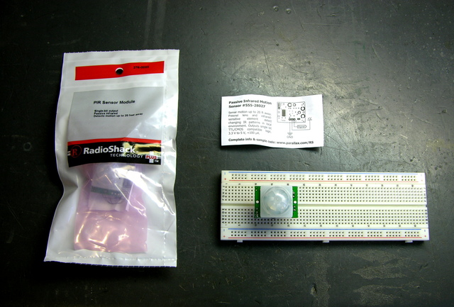
The back cover of Servo Magazine is always an ad from Parallax, and the December issue featured several sensors that will now be distributed through Radio Shack, including a motion sensor for $10.

John and I are getting ready for this spring’s Technology: Art and Sound by Design class; and although I think John will be doing most of the teaching this year, I’m always on the lookout for sensors that would be good for students’ interactive sculptures.

Jason at work suggested that the LED puck could have a motion-sensing mode, to serve as a sort of intrusion alarm.

When two separate events occur simultaneously pertaining to the same object of inquiry, we must always pay strict attention. Or, ah, three events.

Two Parallax / Radio Shack motion sensor kits

I picked up a couple of the sensors last week to try out. The clerk said when they got them, he had thought they’d never sell any. Why am I always the guy buying the weird stuff?

How Motion Sensors Work

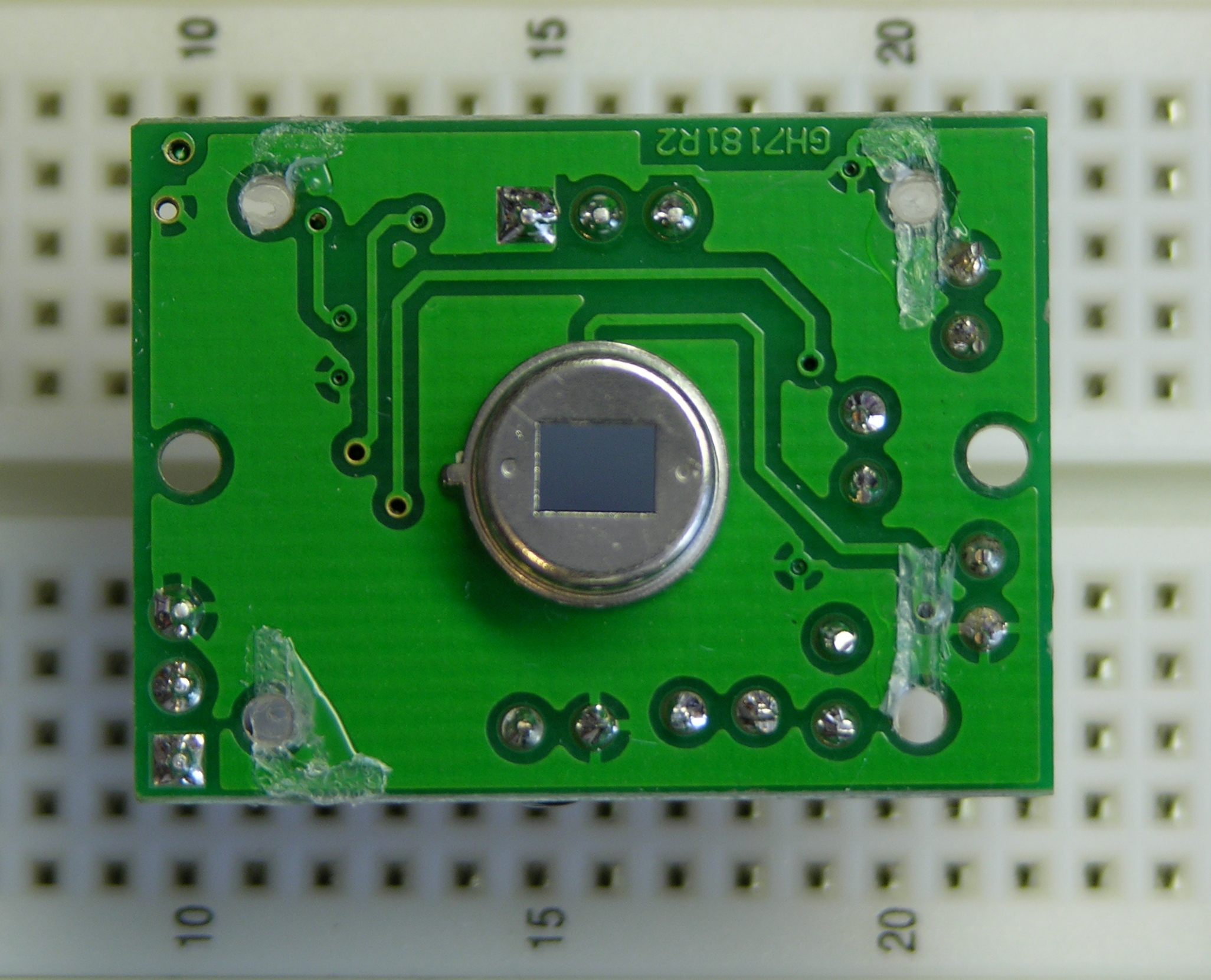
The heart of common motion detectors is a pyroelectric sensor, which is essentially a FET with a window in the case opening onto an infrared-sensitive gate. Changes in the level of IR light with a wavelength corresponding to body heat cause changes in the drain-source resistance, which the circuit monitors.

Parallax pyroelectric sensor

The real trick is that the sensor is then placed behind a multifaceted lens that (loosely speaking) “chops up” the view of the world into smaller cones of heightened visibility and intervening areas of lessened visibility. Think of a stage polka-dotted with multiple spotlights, only actually seeing that way rather than merely illuminating that way.

A body moving from an area of reduced visibility into an area of increased visibility causes a rapid change in the amount of IR (body heat) shining on the sensor, hence a rapid change in its drain-source resistance. The motion detector circuit watches for these rapid changes, and when detected, triggers the alarm. This is why Robert Redford has to move slowly while retrieving the MacGuffin from Cosmo’s office in Sneakers.

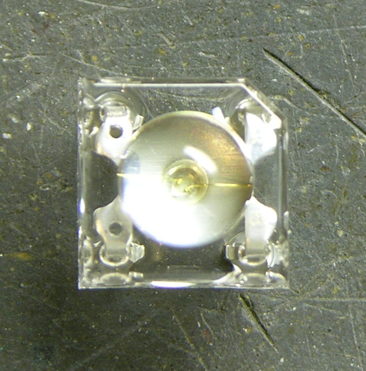
A brief note about the multifaceted lens: It is usually a Fresnel lens, but being a Fresnel lens is a red herring. That simply makes the lens thin and easy to mold out of plastic; it is really the multifaceted nature of the lens that’s important. Closer examination of a motion sensor lens easily reveals that it comprises multiple adjacent Fresnel lenses.

The Fresnel dome of this sensor, by the way, is too large to fit into the LED puck (as, most likely, is the PCB). However, it’s not out of the question to purchase a separate PIR element and mill a multifaceted lens pattern into the puck enclosure above it. It would be an interesting challenge, perhaps for a later version.

The Parallax Sensor

The sensor comes with an absolutely minimal connection diagram, and refers to the Parallax web site for full documentation. The module has a three-pin connector (bottom) for ground/V+/output, and a two-position jumper (upper left) for retriggering mode.

Parallax motion sensor, component side

The power/output header is annoyingly the same height as the other components on the back side of the board, so the sensor cannot be plugged directly into a breadboard for prototyping; it requires an extension. Parallax recommends a servo extension cable; I soldered a three-pin header to a three-pin header socket to make a rigid extension for breadboarding.

The module’s output is active-high. The Parallax documentation indicates that the jumper selects retriggering mode. With the jumper in the L position, the module triggers the output upon detecting motion and then goes low again. With the jumper in the H position, the module is supposed to keep the output high as long as motion continues, but mine does not.

The datasheet indicates that the module needs a “warmup” period of about a minute, during which time it’s adapting to ambient conditions and may trigger randomly. My experience was similar, so anyone using this module needs to be prepared to accept random triggering for a while after startup.

The package and datasheet indicate a detection range of about 20′. I didn’t have room to test this, but I’m willing to believe it until I learn otherwise. Apart from the minor annoyances above, the sensor really is very easy to use, particularly for our class. It seems quite responsive to motion, and certainly responsive enough to pick up gallery visitors not specifically trying to sneak up on it. Output is a very clean 5V, so it’ll be easy for students to interface to the Arduino.

Sensitivity is fixed. It’d be nice to have a trim pot to adjust sensitivity/range, particularly for use in interactive sculpture projects. A Halloween prop-maker going by the name “Scary Terry” has written a nice review of the motion sensor, and includes pictures of mounting it inside PVC pipe to control its angle of sensitivity. I guess with care, the sensor could be angled toward the ground in such a way that it would be triggered only when feet entered a designated area.

Hacking the Sensor

I suspect that most students using this sensor either would trigger a long sequence of actions when motion is first detected, or would like to get a continuous (retriggered) signal the entire time motion is detected. I’m somewhat interested, though, in a much finer-grained notion of “the entire time motion is detected” than that.

By my rough count, the sensor triggers for about two and a half seconds each time it detects motion. It then locks out briefly (didn’t time it — say another couple of seconds?) during which time it’s insensitive before it can detect motion again.

I’d like to be able to get a series of much shorter spikes and much shorter recovery time. I don’t know exactly why; it just seems useful to me.

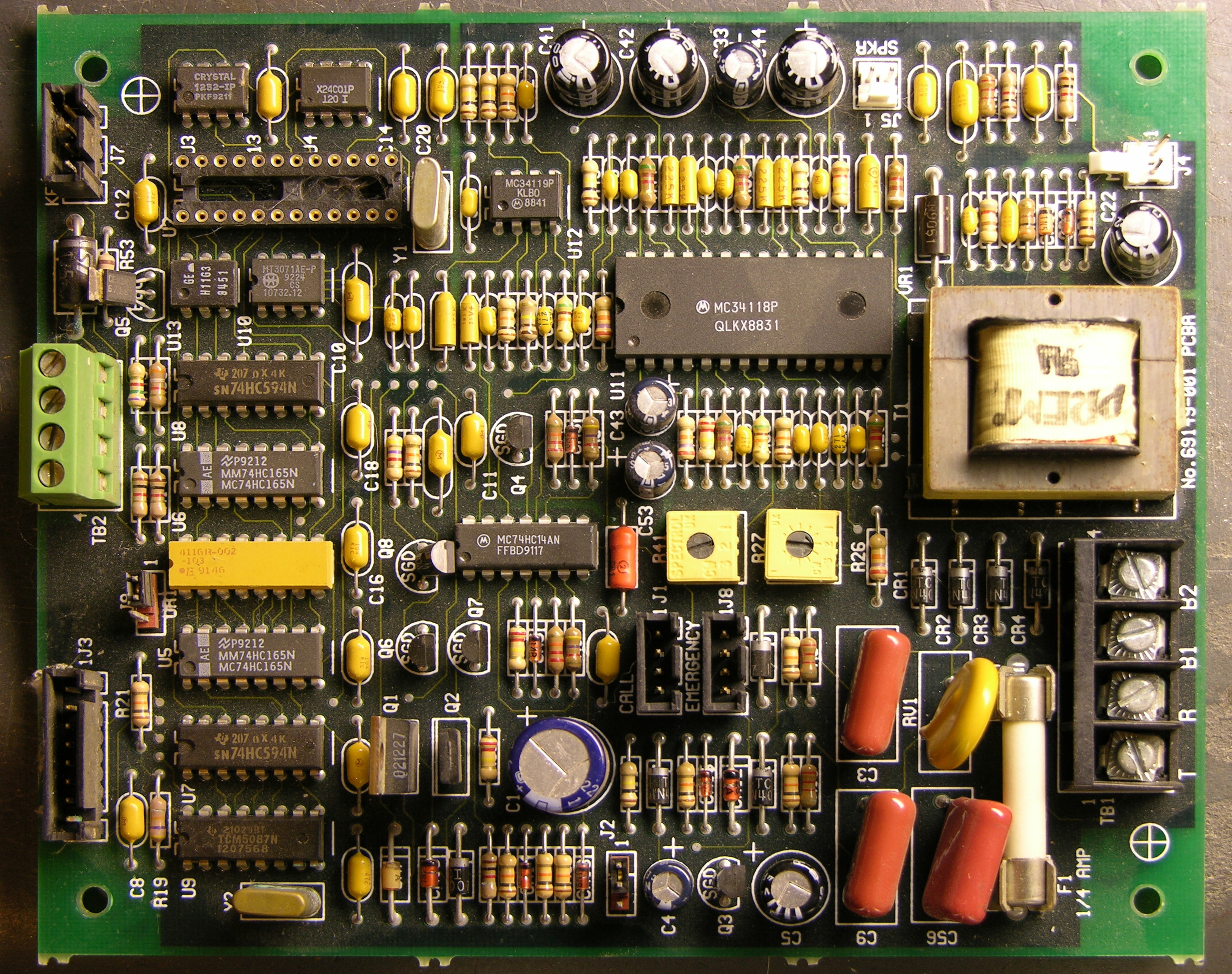
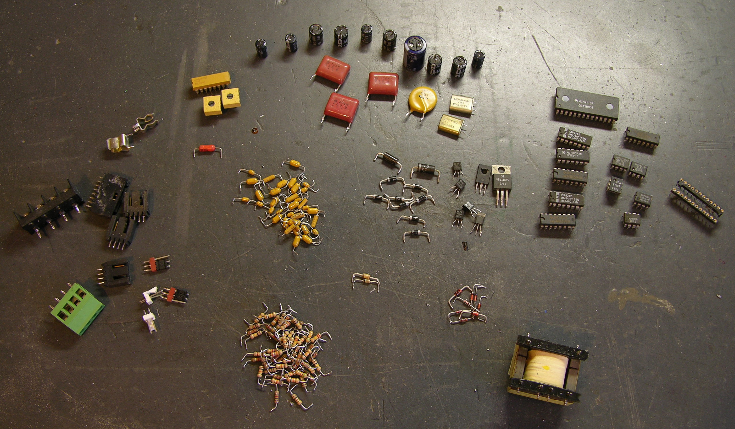
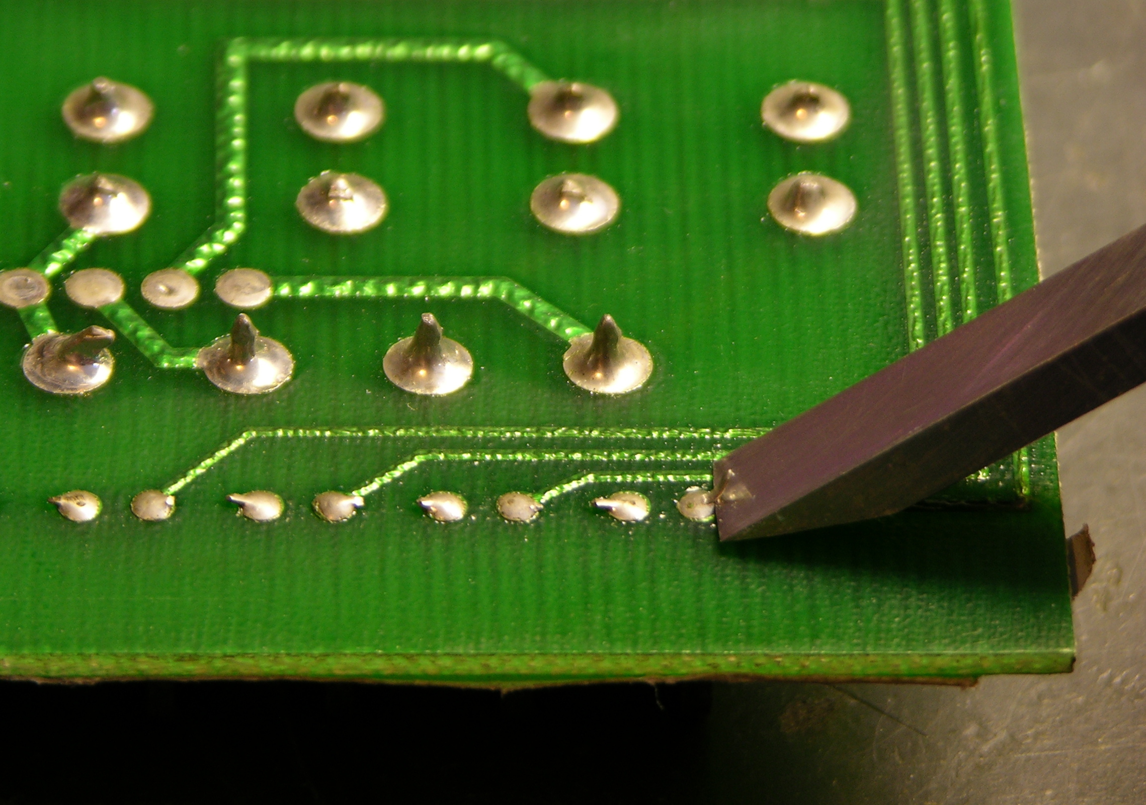
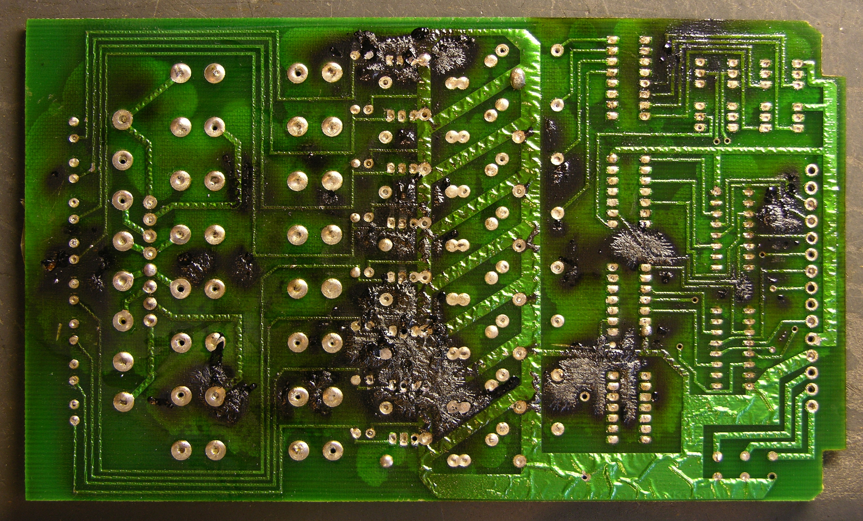
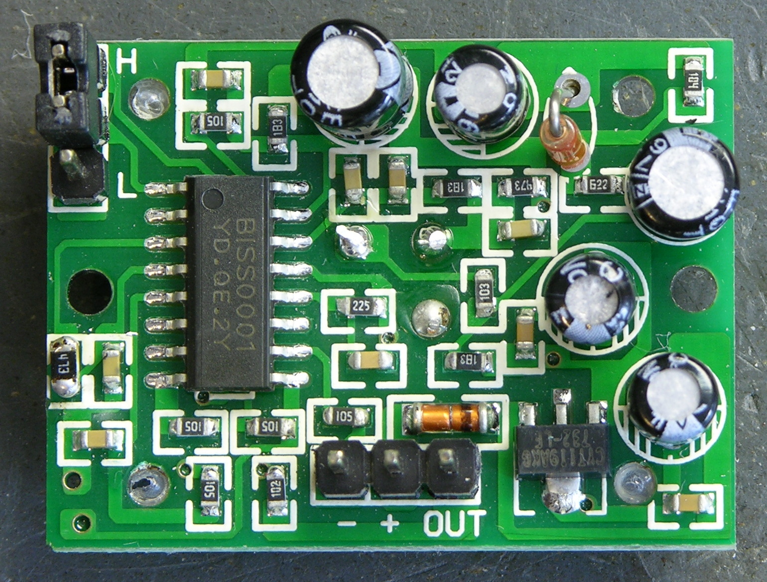
Let’s go back to that component view:

Parallax motion sensor, component side

The IC doing all the work is a BISS0001. The only datasheet I can find for it is in Chinese, yay, don’t read that, sorry. The chip has a bunch of comparators, some logic, a logic section labelled in Chinese, and two timers labelled in Chinese. It looks like it’s probably made specifically for motion-sensing applications.

Fortunately the pinouts and component values are labelled in English, so I was able to make enough sense of the datasheet to understand how to set the timing constants. From the sample application circuit, pin 2 is obviously the master output; and on the pinouts, pin 2 is labelled VO.

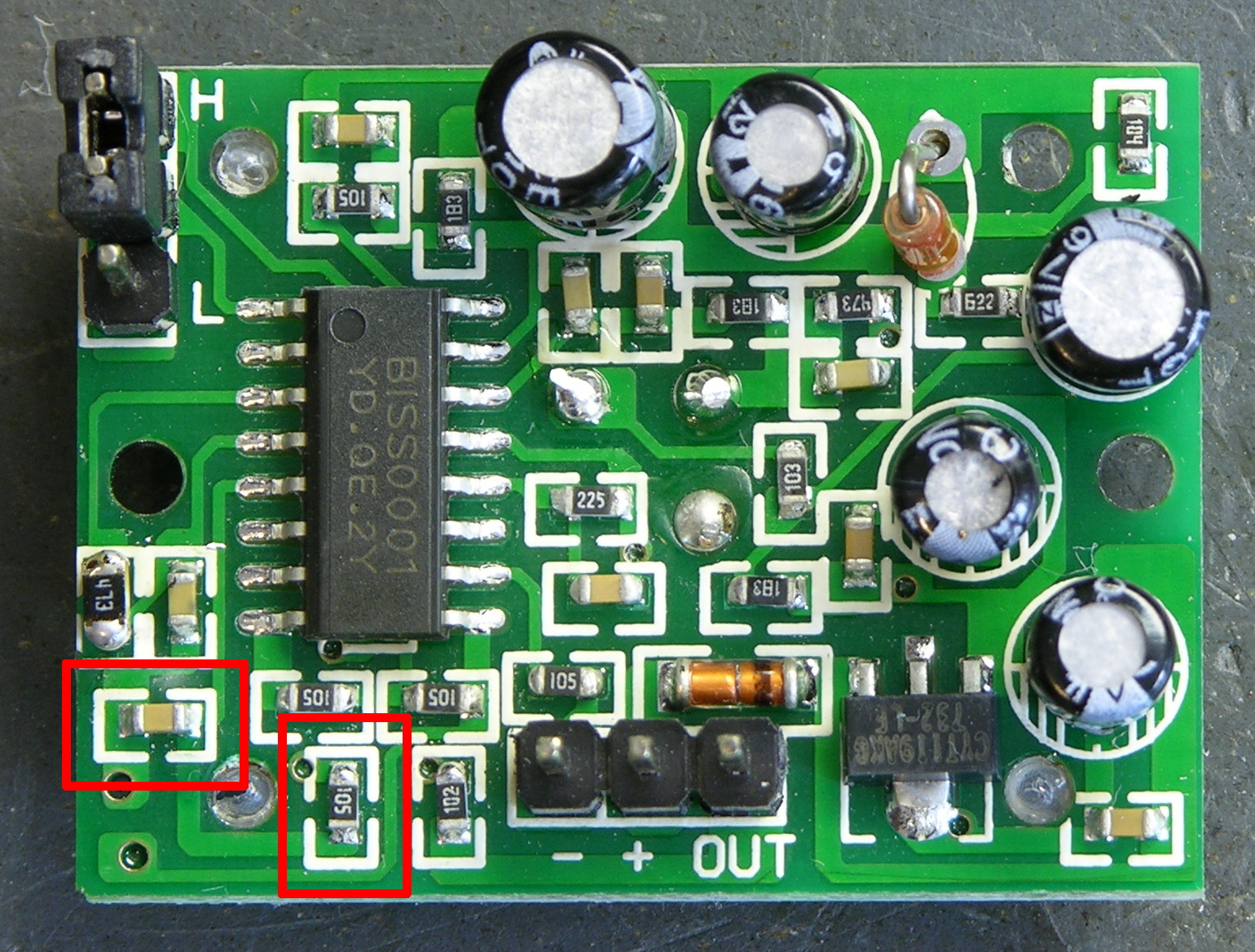
On the timing diagrams, VO goes high for a period labelled TX and low for a period labelled Ti. Just above that, we have the equation TX ≈ 49152R1C1 leaping out at me from a wad of impenetrable Chinese. On the functional diagram, R1 and C1 stack from pin 3 to 4 to ground.

Parallax motion sensor, pulse timing components

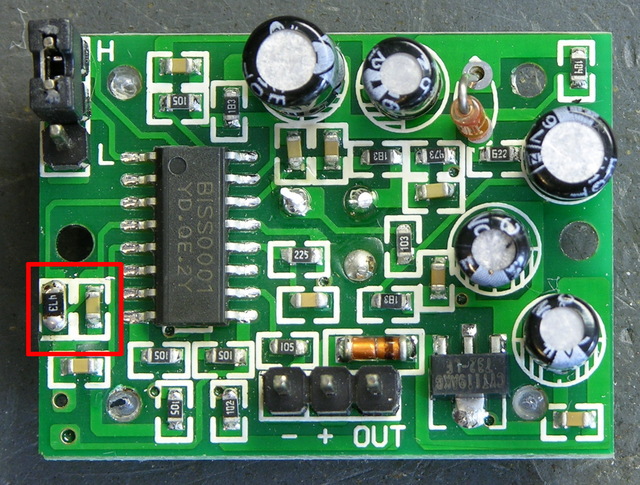
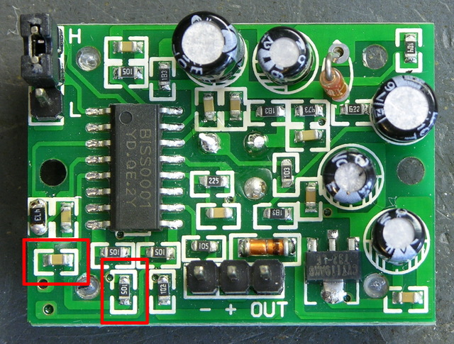
Okay! On the PCB, pin 3 goes to a resistor that said “204.” (Ignore the 473 in the picture.) The resistor and the IC’s pin 4 go to a capacitor, which goes to ground. We’re in business!

The resistor is labelled as a 200KΩ, and my meter confirms that. The capacitor is unlabelled; in-circuit, my meter tests it at about 470pF. Doing the math:

49152 R1 C1 = 49152 * 200KΩ * 470pF ≈ 4.6 seconds

Hm, that’s a little off from the 2.6 seconds I was counting, but same order of magnitude. For a capacitor value that small, I’m willing to believe that I’m getting extra capacitance from my meter probes and from measuring it in-circuit. I think we’re in the ballpark.

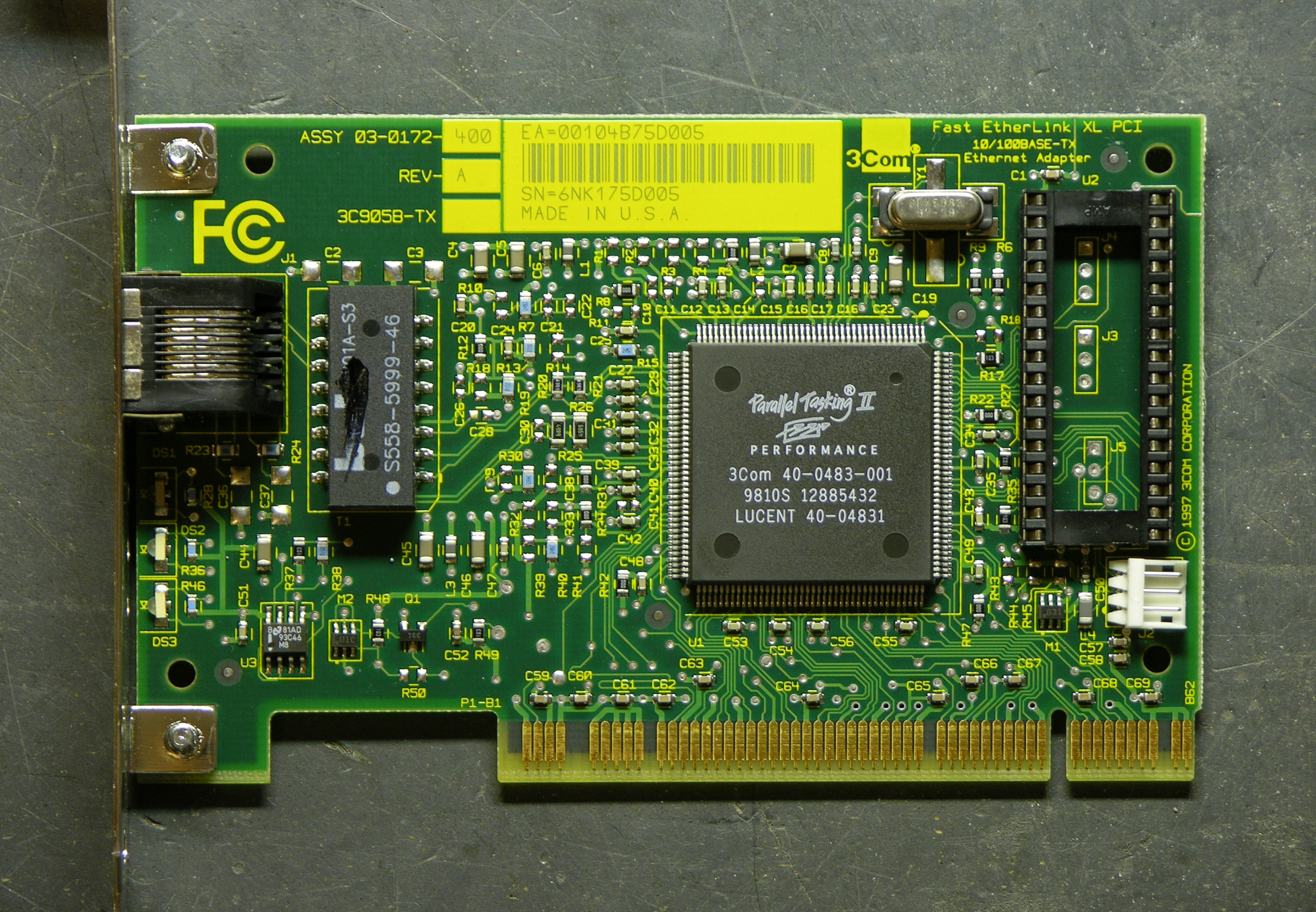
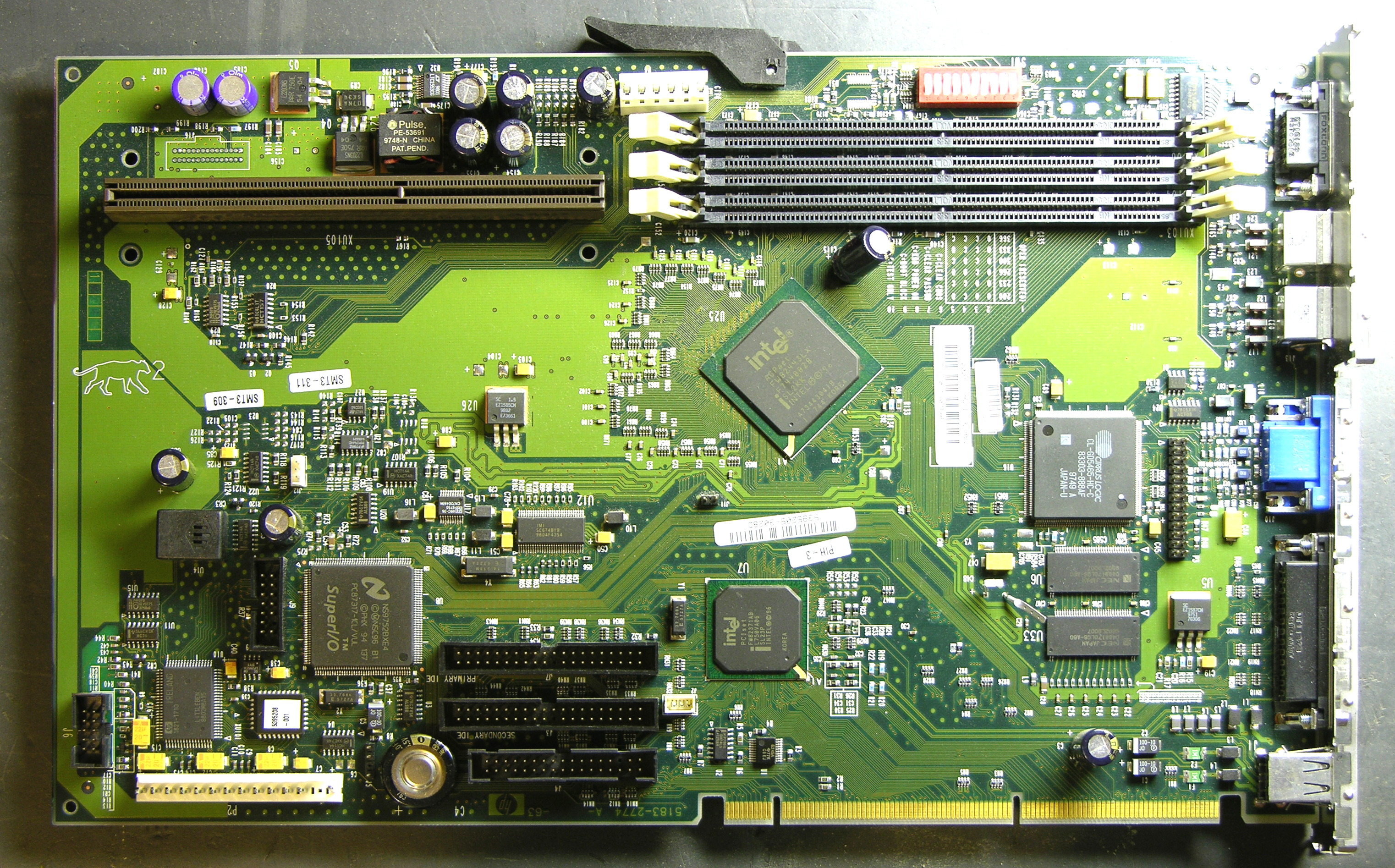
The easiest way to shorten the on-period (TX) seems to me to be replacing the resistor. To take the period down an order of magnitude, I should use about a 20KΩ resistor. After looking at the SMT resistors on a dead PC motherboard, I found a 473 (47KΩ) and figured it was enough smaller to make my point.

I desoldered it by wrapping a piece of heavier wire around it and heating the wire, like Josh suggested, and it worked great. Then out of laziness and because the new resistor was larger than the existing resistor and might not fit the pads well, I just soldered it on top of the resistor that was already there, in parallel. Makes it a 38KΩ resistor instead of a 47KΩ, so we’re even going in the right direction.

I powered up the motion sensor again, waited a minute for it to settle down, and started timing its response. On-time after sensing motion (TX) is now in the half-second range. The absolute numbers still don’t match what the equation says I should get, but the relative values are right on — a resistor with 1/5 the value reduced TX to 1/5 of its former value.

Parallax motion sensor, lockout timing components

Pretty slick! Now I can pick whatever TX I want, be it short or long. I haven’t tried it yet, but the lockout time between motion detection (Ti) is set by R2 and C2 on pins 5 and 6, and they’re easily accessible as well, so I should be able to change that too.

And About that Datasheet . . .

Don’t get me wrong about the Chinese datasheet. Sure I would have been disappointed if I couldn’t read it, but I was actually really pleased that sections of it were in English. I’m aware that people throughout the rest of the world have to learn English in order to do a lot of technical things, and do so with ease and proficiency much greater than that of the few Americans who bother to learn languages other than English.

Bunnie Huang has an interesting blog post that touches in passing on certain types of devices using chips of Chinese manufacture that can’t be found, or can scarcely be found, by searching Google in English:

Just try searching for USB mass storage controller ASICs, or digital picture frame SoCs on Google in English, and then go and open up one of these devices and compare your findings. I bet you’ll find that the chips most frequently used in these popular devices are best searched for in Chinese.

It’s a competitive world out there, and those of us in the west have had it awfully easy for an awfully long time. I know as a mere hobbyist, the technology I use is far behind the leading edge, and I’m not yet impacted in nearly the way of engineers developing new products for market. But the world is changing, no doubt about it, and I hope it’s a while yet before it impacts my ability to tinker.

Merry Christmas to Me!

Friday, January 4th, 2008

When I thought up the LED puck idea, I went shopping for some bright LEDs to put into it. I don’t like the blue+yellow color of “white” LEDs, and I thought it’d be fun to have green illumination, so I found some green LEDs from a Hong Kong [correction: Chinese] eBay seller and bought ‘em. Since I’m pretty sure it costs about the same to ship a package from Hong Kong China if it has a few more items of negligible weight in it, I kind of went crazy and treated myself to an LED assortment.

I won’t mention the specific eBay seller, because I have mixed feelings about them. On the one hand, their prices were very good and their LEDs seem okay. On the other hand, I’m pretty sure it cost them next to nothing extra to ship my whole package than just my first LEDs; but even after requesting and receiving an additional additional shipping discount, I still paid $30 shipping for $35 of LEDs. And on the gripping hand, I paid on December 9 and didn’t receive my package until December 24. It made a nice Christmas present to me, but it made me feel like I was paying shipping by the day instead of by the pound.

Square 5mm LED

Grumbling aside, the LEDs I was shopping for turned out to be not at all what I was expecting, and probably better in every way. This is because I wasn’t paying enough attention to see that they have four legs (I thought they were two-legged LEDs with a square base), but four legs gives better heat dissipation and allows higher current; and I didn’t realize how squat they are, which makes them fit better into a puck; and I saw that they were 1500 mCd but didn’t realize they had a 120-140° viewing angle, which means they output a whopping 4.7-6.2 lumen each. In contrast, my 10,000 mCd 20° blue LEDs only output .95 lumen.

The other stuff I got was a handful of 1W and 3W Luxeon knockoffs, because, y’know, why not; and a constant-current driver board, which I thought would come in handy while testing.

Here are eight of the 5mm LEDs on a breadboard with 100Ω resistors, for about 15mA at 5V or 85mA at 10V (~3V drop). Remember, that’s maybe 5 lumen each or 40 lumen total.

Square 5mm LEDs on breadboard

Let’s see how they fare against the 3W, 70 lumen beast of the apocalypse, wired to the 1W driver without thinking about how that means it’s not running at full power and brightness.

LED driver and 3W green LED

Here’s my desk with about 200W of fluorescent light from the ceiling fixture and the swing-arm lamp.

Desk lit with fluorescent lights

Same scene with the eight 5mm LEDs fed at 10V, and the camera locked to the same aperture and shutter speed:

Eight green LEDs

Same scene with THE BEAST:

3W green LED

Assessment:

The LEDs don’t provide nearly as much illumination as normal room lighting. But then, nobody thought they were going to.

Each set of LEDs does provide enough light to read by, pretty comfortably, even with the light in the same plane as the paper’s surface (i.e. indirect lighting).

According to the camera, half the LEDs for the puck make less light than a single 3W faux-Luxeon driven at 1W. Crap, I should just make a Luxeon throwie and call it a puck. Nah, that’s not really the fun part of the puck idea.

According to my eyes, and my wife’s as well, there’s much less subjective difference in the brightness between the eight 5mm LEDs and the single 3W LED than what the camera appears to show. The math seems to back this up as well (maybe 40 lumen versus some fraction of 70 lumen), so I can’t explain what’s going on in the pictures.

And, oh yeah, LEDs ARE COOL!!!

LED Puck: Blender Modeling

Thursday, January 3rd, 2008

Joel is setting up EMC2 so we can use his CNC machine for milling (DanCAM could mill, but we’d probably have to use DanCAD so we’ve just used the machine for drilling), and I’ve been working on modeling the puck enclosure in Blender.

First, I’d like a better visualization than my crude line drawings; and second, Blender has a plugin to output STL (stereolithography) code, which FreeMill is supposed to be able to convert to g-code, which EMC2 (and everything else in the world) can mill. So at the same time, I get a visual idea of what I’m designing and a CAM file to produce it. Almost like using CAD software. :-)

I am completely new to Blender, which is obvious both by how long it took me to build a satisfactory model and by the amateur appearance of the result. At the end of this post is a plea for education, if anyone wants to teach me how to do it better.

Here’s a view of the draft enclosure from slightly above, rendered translucent (plexi or lexan):

LED puck case modeled in Blender, translucent, from above

The hole through the top will host a waterproofed plunger for the pushbutton switch, but the plunger is absent because I’m only drawing the case for now.

Same draft viewed from below:

LED puck case modeled in Blender, translucent, from below

There’s a shallow recess for mounting a plate to seal the bottom, then a deeper recess for the PCB and battery.

Same case in Blender’s default material (scrith?):

LED puck case modeled in Blender, default material, from above

And from below, which is way too dark but may show a little more detail of the nested recesses:

LED puck case modeled in Blender, default material, from below

Below, detailed information on how I made this in Blender, for anyone interested, or willing to offer advice.

(more…)