I got the sled (or platform) built that will move the drill up and down (Z axis) in my CNC machine. I spent over a week trying to figure out how to make thrust (axial load) bearings for the lead screw, so that all of the motor’s rotary motion is translated into vertical movement of the drill, not vertical movement of the screw itself. I’m still not completely sure that my plan for that will work, but at least I have something to try in the next stage I’m going to build.
I need to find and learn to use an open-source 3D CAD program; but meanwhile, I laid this out in OpenOffice Draw. I had started by tracing the different pieces onto graph paper by hand; but the design didn’t really pick up steam until I got them into the computer, where I could drag and resize components easily. Several times when I thought I was done, I saw the opportunity to shrink things a little closer together — which ultimately translates into the capacity to work a larger piece, as less of the length of the guide rods is consumed by the width of the sled.
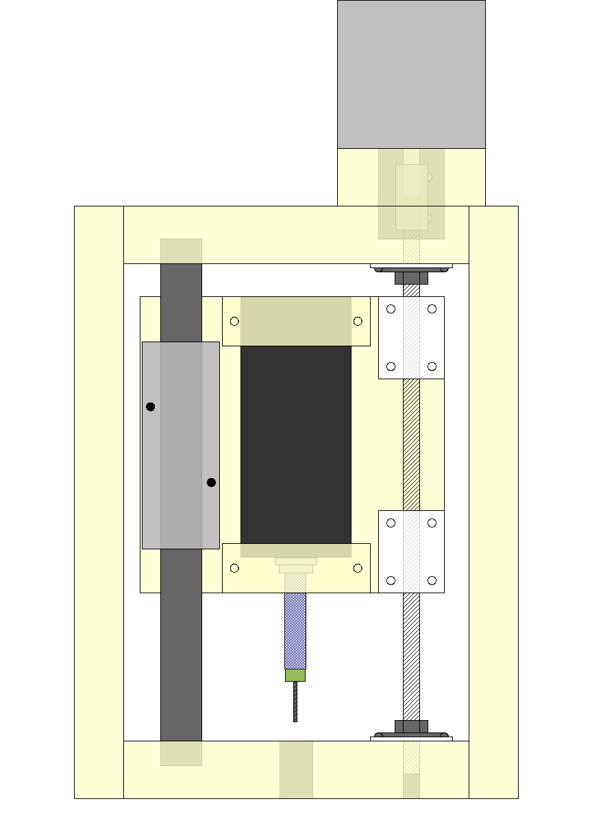
Here’s my final design — final for the prototype machine, anyway. And here’s what it looks like in the physical world — a pretty close match.
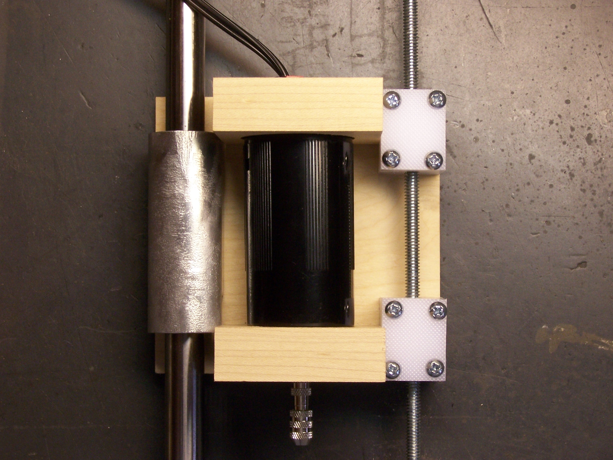
The drill is held by two square blocks with round holes drilled out in their centers. I goofed and cut the blocks to 2 1/4″ instead of 2 1/8″, so the whole platform now fits together a little tightly, and the alignment of the guide rod on the left is a little off; I’ll have to compensate for that later on. And the drill fits a little loosely in the holes because they’re a bit too large, but I’ll add some thin weatherstripping to grip the drill tightly.
The white blocks on the right are built up from two layers of polypropylene kitchen cutting board, superglued together, with a hole tapped through lengthwise for the threaded rod (1/4″ all-thread). When the rod turns, it will push the drill down or pull it back up.
On the left are a bearing glide and stainless steel rod salvaged from a workhorse IBM dot-matrix printer. A computer surplus store in Wichita had a closing sale a few years back, and when no one bought the printers, the owner suggested that I haul them off. I dutifully removed all the electronics, boxed up the mechanical components, and deposited the plastic for recycling. At last the mechanics are finding a new use. ![]()
This assembly will be oriented with the drill pointing down, and a frame will surround it in the Y-Z (vertical) plane. The frame is shown in the drawing but not in the photograph; it’s the next piece to be constructed. The frame will anchor both ends of the guide rod and the lead screw, provide a mount for the motor, and mount two glide assemblies to move the entire frame sideways in the Y (short horizontal) axis.
Motor Mounting
The motor isn’t mounted to the screw right now, since it mounts from the outside of the (yet-to-be-constructed) frame. But I’ve been looking for a good coupler to join the motor shaft to the threaded rod. The ideal coupler would help compensate for slight misalignment between the axes of the motor and the rod, but really good couplers seem to cost $60-$80.
I’ve found one at Jameco that’s much more affordable (just under $5) and looks like it’ll do the job nicely. It has a rubber “spider” enclosed between two pronged pieces. The spider has a little bit of “give” to it, to correct for misalignment. It should also help damp transmission of noise and vibration between the motor and the screw.
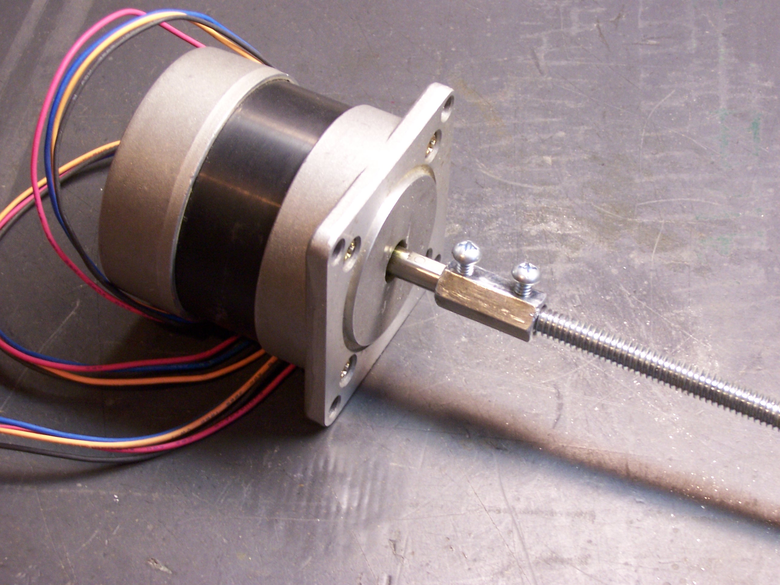
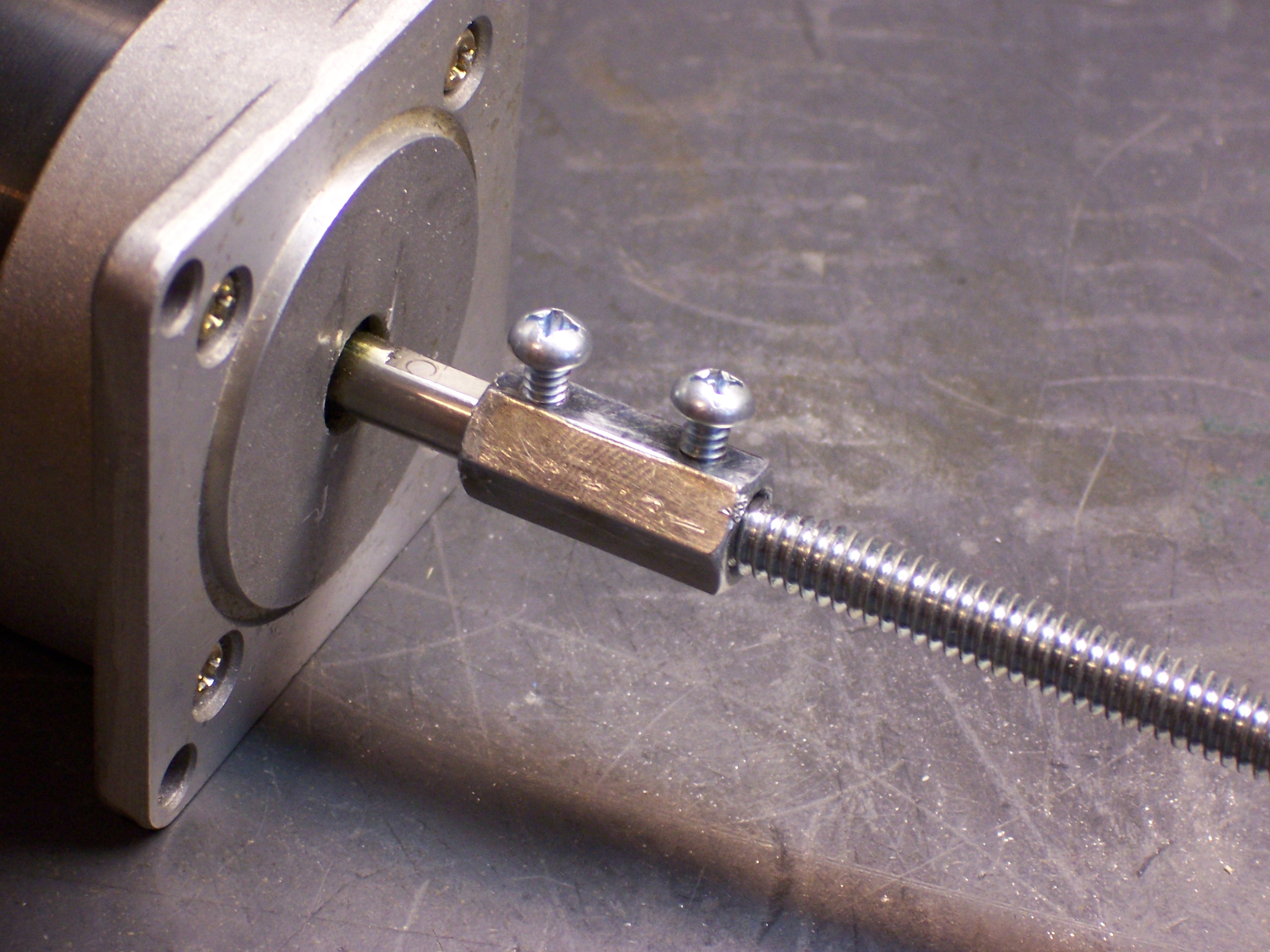
Meanwhile, I’ve built a cheapo prototype coupler myself. I got a $1.49 threaded coupler from Ace Hardware, drilled out half of it to 1/4″, and drilled and tapped holes for set screws. I pressed the drilled end onto the motor’s shaft, filed a flat into the threaded rod and turned it in to the threaded end, and tightened the two set screws. I need to file off some of the set screws’ length, but it’s working okay for a proof of concept.