Archive for the ‘Slim’ Category

Assembling the MakerBot CupCake Extruder

Monday, May 18th, 2009

I’ve been plugging away at the CupCake “Plastruder” in the evenings, and I now have the mechanical assembly mostly finished, pending the arrival of some custom parts.

MakerBot Plastruder plastic extruder

I’m delighted by the clear plexiglas design. And having the mechanical assembly — particularly the extruder — put together really highlights how small this thing is. That’s not a bad thing — for a given build capacity, the smaller the machine is, the better.

(more…)

Two Birds

Monday, April 27th, 2009

I want to replace the abraded power cord on my brother’s sump pump in exchange for his letting me borrow it. Cort needs four panel-mount BNC connectors for an amateur radio handheld direction finder project. Convergence.

VideoCipher II television descrambler, front

Don’t panic. If for some weird reason you need one of these, I have more where this came from.

VideoCipher II television descrambler, rear

It’s a little hard to see from these shots, but the case profile is a weird trapezoidal shape.

VideoCipher II television descrambler, interior

Physically large linear power supply; two main PCBs.

Lithium 1/2 AA cell

Lithium 1/2 AA cell from April of 1989. Rated for 3.6V and still holding 3.69V after twenty years.

VideoCipher II television descrambler, PCB sliding out

Not sure why they used two PCBs (don’t tell me they really needed the extra 20 square inches), but it’s cute the way this one slides out.

Four PCB- / panel-mount BNC connectors

Every one of these had its shield pins broken free of both solder joints. Looked like cold solder, but I assume it was just mechanical stress.

Four PCB- / panel-mount BNC connectors

Voila! Four connectors for Cort. And a power cord for my brother, that I’m out of time to swap onto his pump tonight. Tomorrow, then.

Rackmount Stuff from Slim’s “Dump”

Monday, October 13th, 2008

Here’s the first batch of stuff from Slim’s “Dump” — rackmount equipment that I can’t identify as being associated with anything else from out there.

Rackmount stuff from Slim's dump

I can’t tell that any of this stuff as still useful (which presumably has something to do with why it was out in the Dump in the first place), so it’s destined for disassembly, component removal, case reuse, and recycling. If there’s anything that strikes you as useful, throw a comment down below about what it’s good for, offer to pay me what it’s worth to you plus shipping costs, and I bet we can work something out. I’d love to see some of it go to someone who’d actually make use of it.

(more…)

Cleaning Out Slim’s Dump

Sunday, October 5th, 2008

My friend Slim passed away about fifteen months ago, and this weekend Lawrence and I went out to Pittsburg to clean out Slim’s “Dump,” a storage unit on which Maeve had faithfully been paying rent (bless her heart) until Cort and/or I could come back and empty it.

Slim's storage unit upon arrival

It doesn’t look like much from this view, but there were four grocery-store shelving fixtures and several additional shelves full of miscellaneous old electronics and miscellaneous other things. With the shelves broken down into flat pieces, the contents completely filled Lawrence’s 15-passenger van, floor to ceiling, with all the seats removed.

Here’s the back corner after all the shelves and most of the storage contents had already been removed. There was a fair bit of Southwest Technical Products equipment back there, which is of no particular interest to me but considerable interest to a couple of other people I’m in contact with. I’ll be going through all the cases and boards, sorting into SWTPC versus other stuff, and cataloging and photographing the items for a separate post.

Back corner of Slim's storage after breaking down and removing main shelves

There were several coils of what I believe Cort referred to as aluminum hard line antenna cable, which he also said is outdated and of no further use. Lawrence will take drop it off for scrap metal recycling next weekend unless by some miracle someone indicates they think it’s still worth something before then.

Coils of hard line antenna cable

This TI Silent 700 hardcopy terminal with the dual cassette drives on top really tickles me. This DigiBarn post suggests they could upload and download content over the terminal line. I learned to program on teletypewriters on a timesharing system, and I have a soft spot for hardcopy terminals. The cassette drives are definitely icing on the cake. And I think I have about a dozen more of those drives, loose, from Slim.

Texas Instruments Silent 700 hardcopy terminal with tape drives

The “silent” in the name refers to the thermal paper, by the way, and I’m not sure I like the idea. Using a hardcopy terminal wouldn’t really be the same without the distinctive clatter of the DECWriter pins against the flat metal platen, and the almost anthropomorphic sound of the printhead sliding slightly to the right, to get out of your way and let you see what had just been typed, each time the terminal was idle for a couple of seconds.

Mission accomplished. Just a few non-electronics items left for Maeve to deal with.

Slim's storage, empty

Back home and unloaded, here’s what appears to be a campus A/V distribution patch cabinet. It has what I think are SO-239 connectors on the top (I’m not a radio guy) and 1/4″ sockets on the bottom. I’d be happy to part with the SO-239 panels if someone had a use for them.

AV distribution rack from Slim, front

Although it looks messy now because whoever uninstalled it did so rapidly, the cables were very nicely routed and carefully bundled and laced with waxed string, an art that I fear has become lost.

AV distribution rack from Slim, rear

Finally for today, my first treasure of this trip: an HP 122AR rackmount oscilloscope. Just last week, I was talking to Jeremy about installing a power inverter in my cargo van and setting up a gig box with a rackmount scope and some other tools for portable/mobile electronics troubleshooing and repair. If this works and it’s not too dep, it’ll be lovely for that! (Of course, I’ll have to make it clear that the gig box needs to be treated with care and not dropped out of the side of the van, but I think I can handle that.)

HP 122AR rackmount oscilloscope

Looks like it has two channels, which is cool. For this application I’d be even more excited if it had two axes (great for troubleshooting vector arcade games, and I do have a couple of two-axis scopes already, just not rackmount), but I’m thrilled with what I got.

Now I need a few sunny evenings or Saturdays to photograph and catalog the rest of what we brought back. There’s a lot of stuff that looks no longer useful to me, and I’ll be willing to work something out to get it into the hands of the right people if it’s still useful to someone else, so I hope to post good pictures and descriptions in the coming weeks.

“Airduino” Scungy Anemometer Part 1: Detection and Amplification

Sunday, June 8th, 2008

Necessity is said to be the mother of invention, and 90+°F daily temperatures with the air conditioner on the fritz made me feel pretty inventive.

Arduino anemometer, angled view

Our air conditioner was low on refrigerant and the blower fan motor may be running slower than spec and not moving enough air. Between the two problems, the expansion coil inside the furnace housing would ice up, over a few hours completely blocking the airflow and preventing any meaningful heat exchange. I’d then have to switch off cooling mode and run only the fan for a few hours to melt the ice.

On a weekend when I was home all day, I discovered that I could keep the house fairly cool by setting the blower fan to run all the time, manually monitoring the airflow out the vents, and cycling the AC off when airflow was restricted and back on when it opened up. Which sounded like a perfect job for a microcontroller.

Introducing the scungy anemometer, or Airduino v0.1, for short. Also introducing real-life code using the Arduino’s external interrupt pin(s).

(more…)

Treasures from Slim

Tuesday, December 11th, 2007

An ice storm was predicted for today; and in anticipation, the university shut down. Even faculty and staff don’t go in for a full shutdown.

Icy trees on my street in North Newton

Temperatures must have been quite a bit higher than expected; because although there’s some ice on trees, all the freezing rain that hit the ground stayed wet and is draining away.

Icy tree looming over garage

So here I am at home, waiting for more limbs from my neighbors’ tree to fall on my garage, and catching up on some electronics.

Another Weekend of Cleanup

Cort and I went to Pittsburg this past weekend to help Maeve clean up more of Slim’s stuff. The focus this time turned out to be books, but we each plundered other areas as well.

Ohmite resistor cases

I adore these vintage resistor storage cases. The drawers are about 1/2″ high — you don’t need much more than that to store resistors — and they’re totally dreamy. (Um, yup, I’m a geek. :-) )

Engler Hour Meter

Cort and I found this on a shelf in Slim’s garage:

Engler hour meter, angle view

It’s an Engler Instrument Company hour meter model 10N, and I think it’s absolutely gorgeous.

Engler hour meter, face

It wants to be built into a rich walnut case for something. (I’m not an active steampunker, but I definitely admire real and faux antique gear with wood and brass and glass and gleaming chrome and flicking needles with paper scales behind them.)

Engler hour meter, back

Give it 110VAC and it counts hours. The case is riveted shut, so there’s no resetting it. Still, it wouldn’t be that hard to run it long enough to reset — only about 35 months. (I’m going to need a good reason to do that, though . . .)

Slim’s Microcontroller Development Drawer

Slim's microcontroller development drawer

I’m not sure which cabinet this came from, but Maeve had taken a whole drawer full of Slim’s microcomputer and microcontroller development gear out to the garage. Cort and I picked through it, boxed it all up, and brought it home.

Some of the detail that follows is as much an inventory for Cort and me so we know what we have and where it’s packed, as it is intended to be of general interest.

PIC sticks

Lots and lots of microcontrollers and related chips: Two sticks of TL064 op-amps, three sticks of PIC16C55s, three of PIC16C56es, two of PIC16C57s and two UV EPROMable chips, two sticks of PIC16C71s, a stick of ISD 4004-16MP 16-minute audio recording chips, a stick of ADCs, a bunch of miscellaneous Mozer Digitalker chips, an XC68HC705K15, and a couple of MC68HC811E2INs.

Circuit Cellar RTC52 and RTCIO kits

Circuit Cellar RTC52 and RTCIO kits, unassembled. I was never a subscriber, but these appear to have been the foundation of many Circuit Cellar control and automation projects; see for example this touch-tone remote-controllable home automation system from 1991.

PICBASIC development kit

A PICBASIC development kit.

Microcontroller development boards

Various microcontroller development boards, at least two of each, and heavily biased toward Motorola.

M68HC705KICS development board

An M68HC705KICS programming board, adorably fitted in a box with cutouts for the power leads and ribbon cable, so it never has to leave its nest.

SWTPC boards

A RAM board and two MP-09A CPU boards from a Southwest Technical Products Corporation 6800/6809 computer, circa 1978. I would really like to find a good home for these with a SWTPC collector. I think there’s a related chassis in storage as well, which I’ll dig out next time.

LCD screens

Couple of LCD screens in “widescreen” format. :-)

Speech synthesizer board

A very funky, battery-powered speed synthesizer board. Cort said Slim picked this up somewhere (probably at the Dayton Hamvention) and the two of them (particularly Cort) poked at it for a long time figuring it out. They were able to get it to make noise, and it has both recorded phrases and a phoneme generator, but they never found any documentation about the dictionary and weren’t willing to spend the time to catalog it by trying every address. Cort also said it draws half an amp.

Huge pushbutton switch

And a very large, datacenter-style pushbutton switch. Sweet!

Slim’s Prototyping Station

Sunday, September 23rd, 2007

Last weekend, Cort and I went to Pittsburg to help Slim‘s wife go through his mounds of AV gear and electronic parts. A couple of guys from the amateur radio club joined us, and we spent Friday night and most of the day Saturday identifying and sorting things.

For all that effort, we basically got the van cleaned out and the family room counter cleaned off. We could tell we’d made a dent, but there’s obviously a huge amount left to do. Nevertheless, Maeve was overjoyed at the work, and I think the most important thing we accomplished was helping her reduce how overwhelming the job seemed to be. Plus I got her DVD player, worldwide and NTSC-only VCRs, and Tivo hooked up to her TV so she can watch movies again.

As we sorted, we grouped things into six rough categories:

  • things that Maeve will use herself
  • expensive items that she should sell (possibly to one of us, possibly elsewhere)
  • miscellany that one of us was interested in
  • miscellany to take to the radio club grab pile
  • stuff (mostly non-electronic) that won’t bring enough money to be worth the hassle of selling, but is still potentially useful to someone, to take to the thrift store
  • trash

Each of us took home a few things, and I have others to talk about in due time; but the one that impresses me most was Slim’s prototyping station. Cort often talks about how important it was to Slim that people use things and how ready he was to give things away to people who would actually use them.

The radio guys aren’t really building things these days; Cort said that he and I are the only ones doing circuit design, with me doing the most right now. Because of that, Cort insisted that I be the one to take the station. I am very honored; and with great honor comes great responsibility.

The Station

Slim's prototyping station

Slim designed and built this himself. To me, it not only is a very impressive piece of work, but also reflects a lifetime of experience prototyping circuits and knowing what features are useful to have at hand. A station like this should come with a manual, and it’ll take me some time to figure it out and become fluent with everything it offers.

Myriad Connnectors

Slim's prototyping station, top view

Starting at the top, the station has a multitude of connectors: DB-25 male and female, a card-edge socket that reminds me of my VIC-20 days, 1/4″ and 1/8″ jacks, barrier strip, RCA, BNC, and binding posts.

Slim's prototyping station, breakout of top connectors

Each connector breaks out to well-labelled wire sockets in an area near the left of the front panel. These pin sockets are a Slim signature item — he used them on all of his breakout and prototyping stations, and I’ve never seen them anywhere else.

Next to the connector area, in the right of the photo, is an area for a signal generator that looks like it wasn’t finished. Based on some conversations I had with Slim about signal generators, my guess is that he intended to take the board out of a commercial unit, embed it inside the case, and extend its controls to the front panel, rather than construct his own from scratch.

Power Suppply

Slim's prototyping station, power supply

At the far left of the front panel are power supply connections providing variable + and – voltages and dual +5V supplies. If I’m following correctly, the two 5V supplies run to the ends of the rail above the breadboards, and are jumpered down to the left and right breadboard sections from there.

LEDs

Slim's prototyping station, LEDs

In the upper center are two six-digit sets of seven-segment LEDs. The lower set appears to be broken out for matrix drive (labelled Digits 1-6 and Segments a-g at the left), and the upper set appears to have integral decode/drive (individually labelled A-D and Dp under each digit). There’s also a set of sixteen LEDs for individual use.

Microcomputer

Slim's prototyping station, microcontroller breakout

The upper right corner has a microcomputer section with a 24-pin ZIF socket for EPROMs, selectable between 2708 and 2716 (this is old school) and presumably a microprocessor hidden behind the panel. Given the PIA labels, I’d guess it’s a Z80, but it could be something else with an external PIA chip as well.

Everything Else

That’s all the closeup pictures I took, but there are a few more features I’ve already figured out. The row of black knobs across the center are potentiometers of commonly useful values, broken out to pin sockets underneath each one. The row of tracks between the pots and the breadboards delivers power and also has four buses labelled A-D.

Above the tracks are wire sockets for the switches and pushbuttons across the bottom of the case. There appear to be six logic inverters. And at each end are two sets of LEDs labelled H (red), L (green), and P (yellow) — I assume logic probes showing high, low, and pulse.

And of course a breadboard, generously sized, with a bunch of parts still on it. It has a couple of TL064s, Slim’s and Cort’s favorite op-amps, but it doesn’t look like it’s really a circuit in development. It looks more to me like it might be leftover parts that he was moving out of the way.

Using It

My challenge now is to learn to use it effectively. I always have enough clutter on my workbench that I have preferred using small breadboards and pulling out only the parts and connectors I need at the moment. On the other hand, the benefit of a prototyping station like this is always having everything at hand, saving the time of having to dig out the right connectors and displays.

It’ll definitely take some to get used to, and to determine which method really works best for me. Maybe eventually, it’ll inspire me to build my own comprehensive station that’s just right for me; and with Cort’s help, hand Slim’s station down to the next generation of experimenter.

Battery Meter

Sunday, January 7th, 2007

Battery Meter Prototype

Here’s a project that I’ve been kicking around for a long time (three years–I guess that’s not so long compared to some of my projects :-| ) and finally built–a battery meter. My friend/enabler Slim Cummings in Pittsburg gave me a couple of surplus 3-1/2 digit, .2V panel meters, and I thought they’d be perfect for testing the freshness of AA and AAA cells.

Meter

The meter was the inspiration for the project. It has a 3-1/2 digit (a 1 plus three 7-segment digits–1888) display, a configurable decimal point, and an Intersil ICL7106CPL LCD/LED Display, A/D converter chip. You give it 9V supply, a jumper for the decimal point, and a voltage input; and it samples the voltage and drives the LCD. It’s a very nice package that just begs to be used for something interesting.

Tester Case and Battery Holder

Parts to Build a Battery Meter

The physical aspects of the project actually took much longer than the electrical. First off, I wanted to find a case with the following characteristics:

  • The case would be held in portrait orientation.
  • The meter would fit across the width of the case, with the battery holder below it.
  • I could fit a 9V battery inside the case to power the meter.

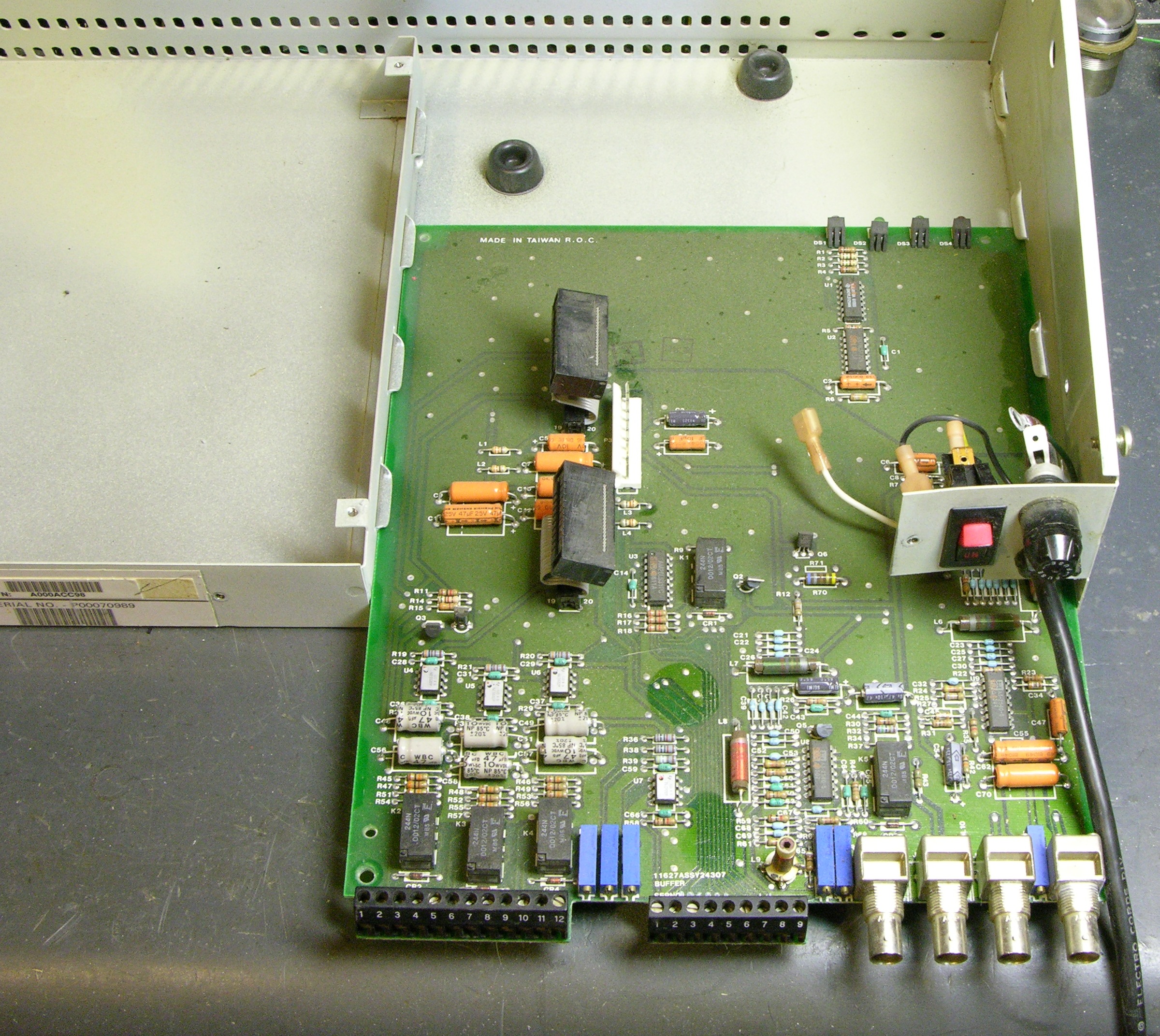
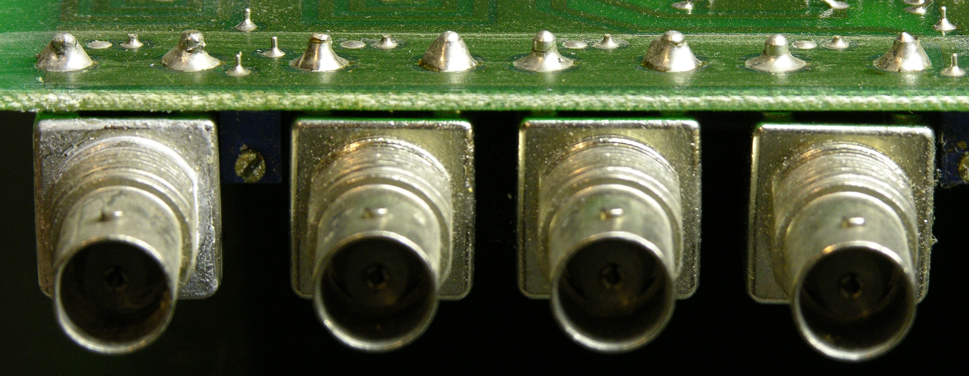
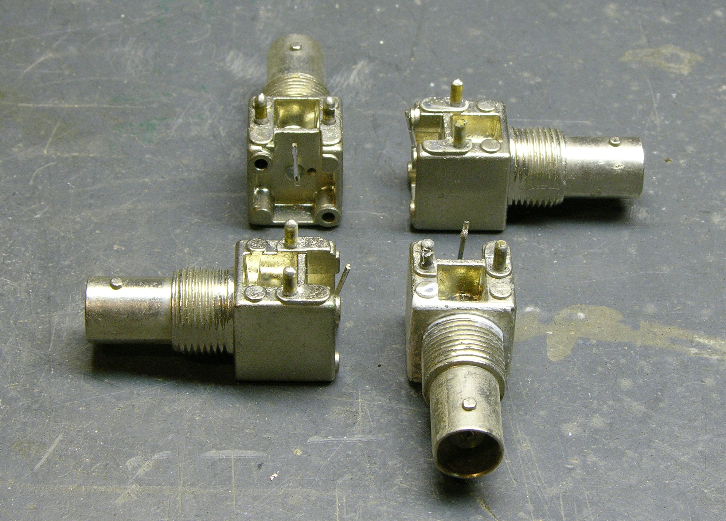
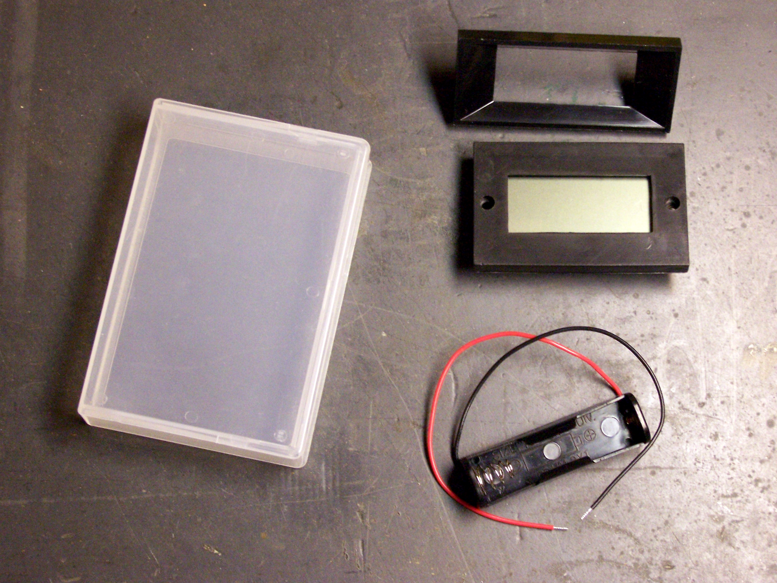
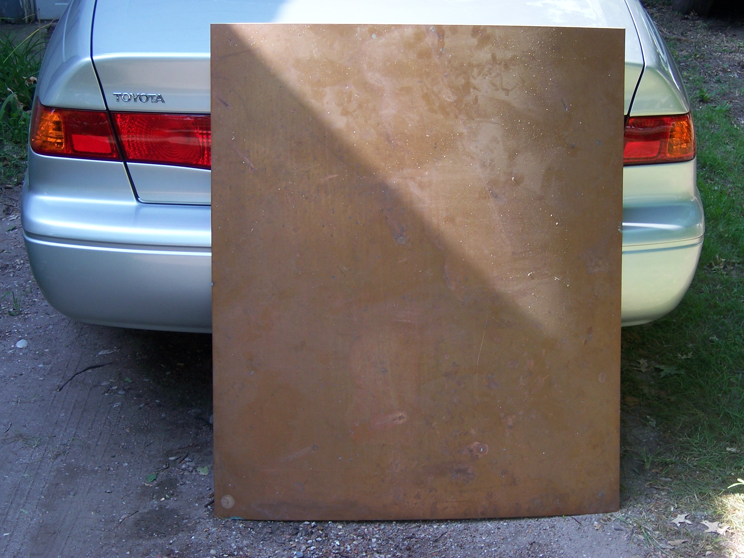
I figured I’d find a plastic project case from Radio Shack with a 9V holder in one end and enough room for everything else to fit . . . no such luck. I figured I’d find something in my junk bin that I could reuse–I was coming close with some old and broken copper-to-fiber media adapters, but they weren’t quite right. Finally I stumbled across the idea of using the plastic case from a data backup tape, and I rummaged around until I found this KAO 8mm data cartridge case.

I’m not wild that it’s translucent–I don’t like seeing the guts of things when I’m using them–but it’s the perfect size. The meter exactly fits across the width, the 9V battery exactly fits in the thickness, and it’s in portrait format. Plus I guess it’s kind of cute opening the case like a cassette case to change the 9V battery.

Single AA Cell Holder

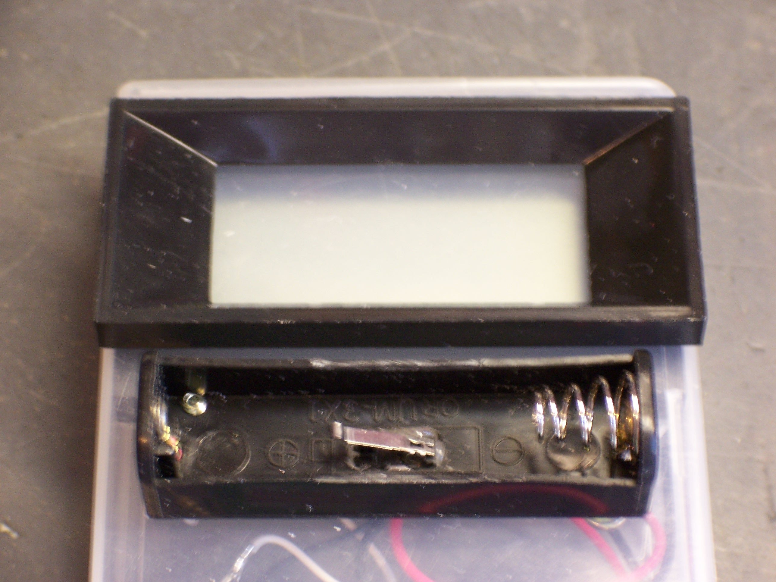
I picked up a single AA battery holder at Radio Shack a couple of weeks ago, and had to mod it a bit to fit it onto the case the way I wanted. The leads originally routed out holes in the ends of the holder, but I wanted them to go straight down through the case. Fortunately, there was already a hole underneath the terminal at each end (you can see the one at the right end of the above picture), and I was able to fish the wires through and tug them into position to make it work.

The holder also had tabs curving slightly around the front, to help hold the AA cell inside. Since I want to be able to insert and remove cells quickly, I removed the tabs by scoring the plastic flush with the rest of the front of the holder, then snapping them off. I also confirmed at this point that a AAA cell would make contact with both ends of the holder, even though it wouldn’t be held as securely. (AAA cells are shorter than AA cells, as well as thinner.)

Project/Tape Case with Mounting Holes

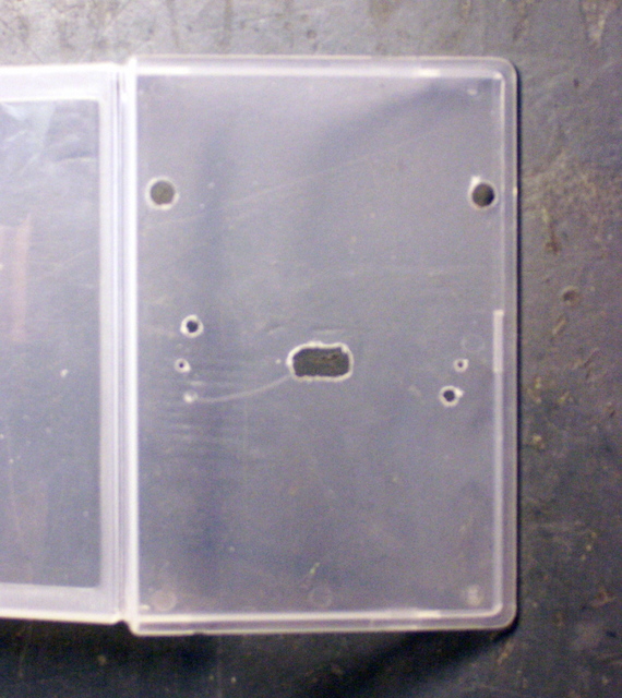
I drilled mounting holes in the case for the meter and battery holder, as well as holes for the wires to go through. The plastic was so soft, I didn’t even bother chucking the bits into my drill for most of the holes–I just turned the bits a few rounds with my fingers and I was through the case.

Stepped Drill Bit Set

I did get to use my stepped drill bit set to enlarge the meter’s mounting holes–the bezel’s posts have larger-diameter plastic shoulders at the base, my mini-drill doesn’t have bits that large, and the stepped drill bits do an excellent job of enlarging while remaining concentric with the pilot hole.

The last tricky bit of work with the drill was the big ugly hole in the center of the picture of the drilled case. I needed a power switch for the meter, but I was loath to have to have to slide a switch or press a button every time I wanted to use it–I wanted it to spring to life when a cell was inserted to test. Plus for reasons to be described a bit later, I planned for a pushbutton on the front already, and I didn’t want to have two.

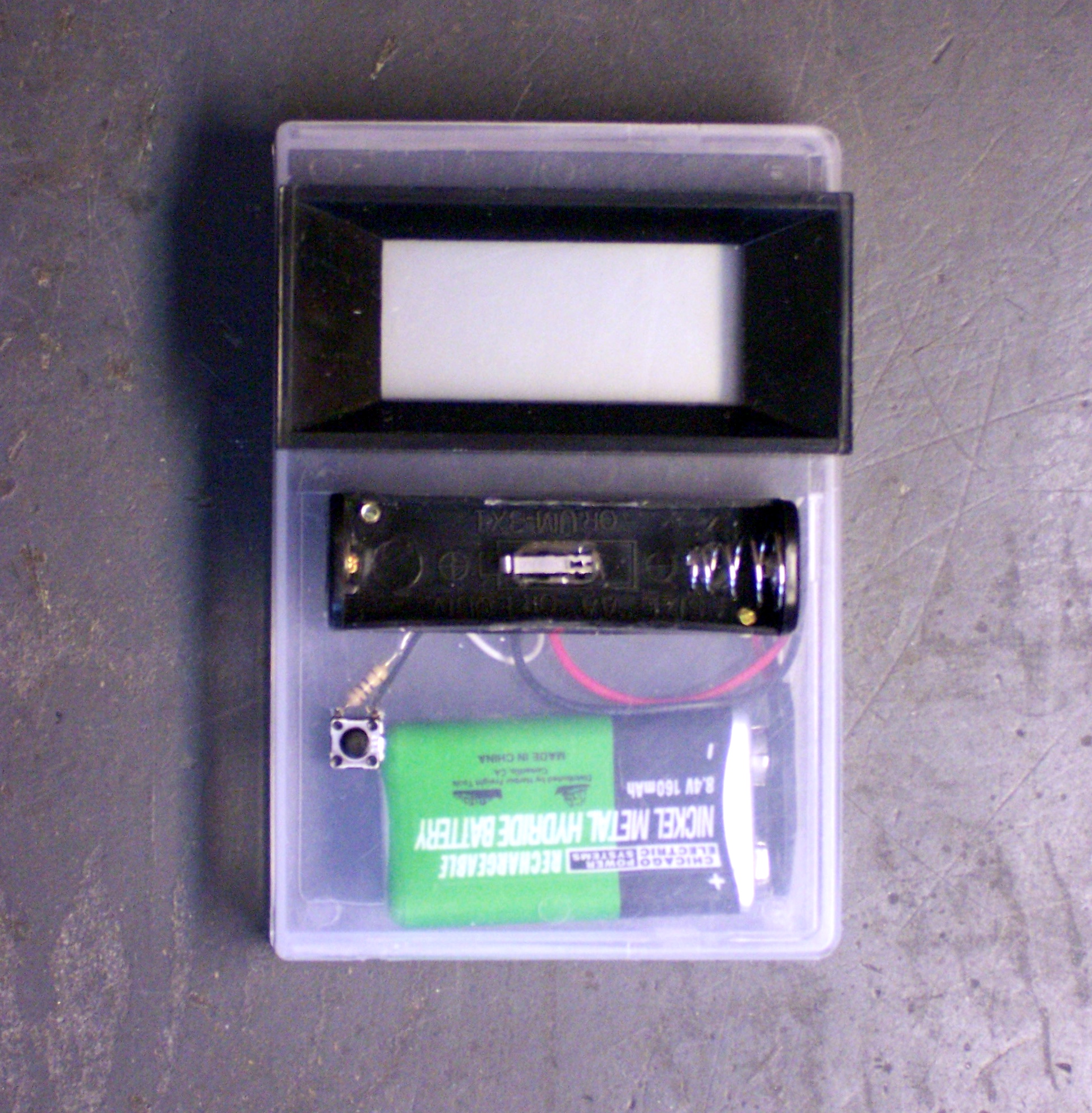
The solution was simple enough–a pushbutton switch inside the battery holder, actuated by the insertion of the cell itself. I salvaged a tiny microswitch (“nanoswitch???”) from a dead CD-ROM drive (a limit switch from the optical sled), reamed much too large a hole in the case and battery holder, poked the switch in from underneath, and hot-glued it in place.

Meter Wiring

Digital Panel Meter, Component Side

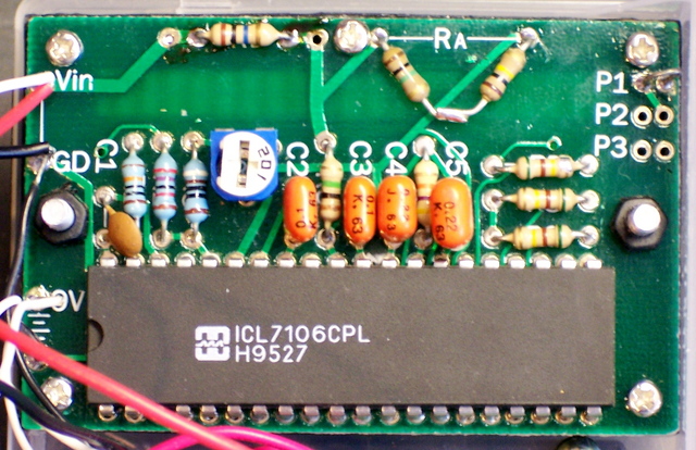
The meter board is built for a range of 0 – .1999 (.2) V, but has pads to set the placement of the decimal point and to provide your own voltage divider to adapt for other ranges. The documentation gave the resistor values to adapt for 20V and 200V, from which it was easy enough extrapolate the nominal values for 2V operation: 9MΩ and 1MΩ. Well, I have 1MΩ resistors on hand, but not 9MΩ, and certainly not precision.

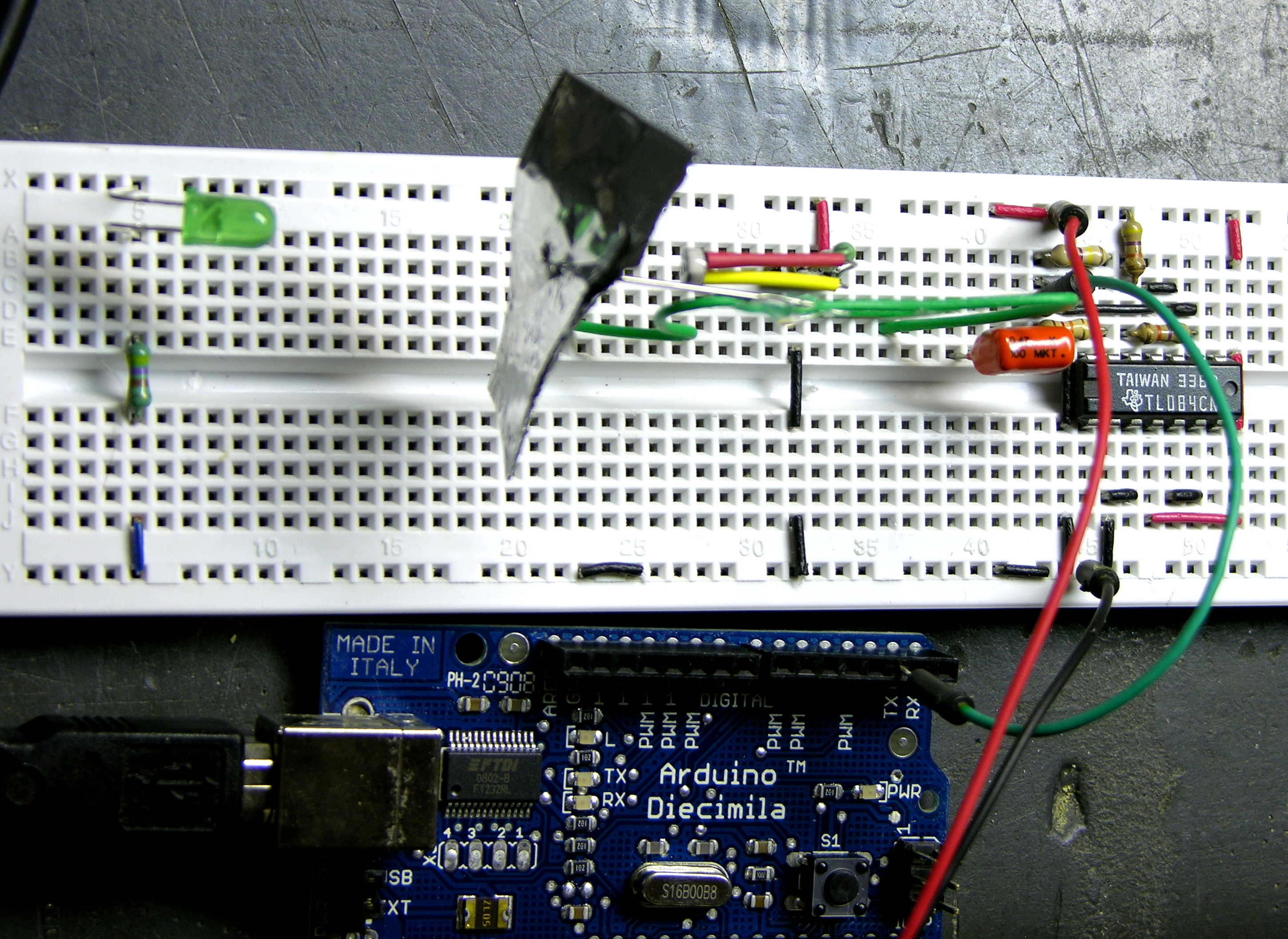
Fortunately, 9:1 ≅ 10:1.1, so I put a 10MΩ resistor into the pads for RB (upper left) and chained a 1MΩ and a 100kΩ in series between the pads for RA. (Those lap-soldering skills from a summer of module assembly at IFR Systems do come in handy.) Also fortunately, the calibration potentiometer had a generous range, so I was able to work around the 1% difference from the nominal ratio.

I also guessed (correctly) that the proper position for the decimal-select jumper was P1, which was missing from the voltage range chart.

Assembly

I had one more set of components to add, but I couldn’t resist wiring it up to see how it worked so far.

Battery Meter, Component Side

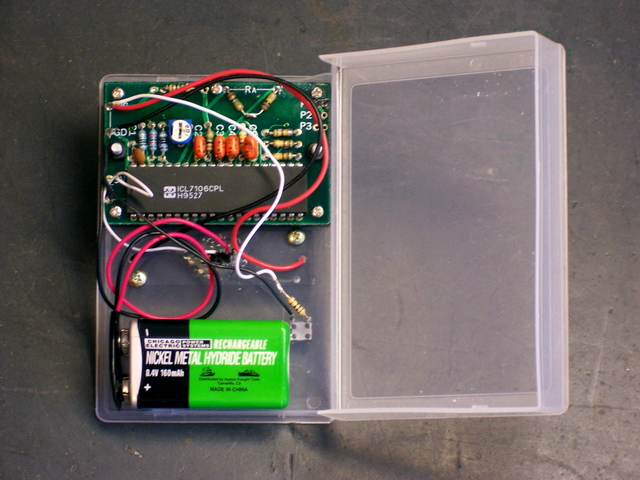
I soldered the 9V battery clip’s ground lead to the ground connection at the lower left of the meter board, the positive lead to the microswitch glued into the AA holder, and the normally open (NO) lead from the microswitch to the supply connection on the meter. I also soldered the AA battery holder’s leads to the Vin connections at the upper left. If you look closely enough, you may see that I just tack-soldered them in place with a lot of exposed wire a the end; I plan to come back and organize the wiring more carefully, and didn’t take a lot of extra effort at this point.

Meter in Action

Battery Meter in Action

And it works as planned! Not that there was much surprise, but it’s still nice when a project comes together. I was also pleased that the (undocumented) position of the decimal point was correct. Further, I was hoping to avoid cutting a large hole in the box for the panel meter; and I find it adequately legible reading through the nearly transparent case, without a hole.

I put a AA cell into the holder, the switch activated beautifully, the meter sprang to life, and I had a reading of the AA cell’s voltage. I measured the cell’s voltage in situ with my best voltmeter, calibrated the panel meter’s reading via the potentiometer on the back, and measured with my good meter once more to make sure the voltage hadn’t drifted while I was adjusting. Good enough!

Load Testing

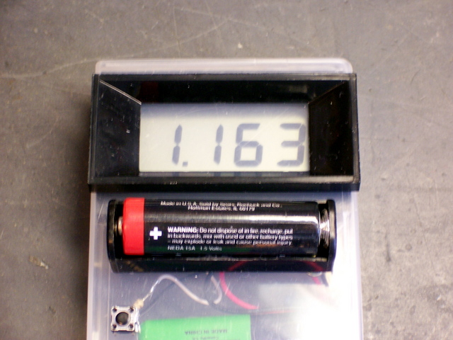
Finally, I drilled two more small holes in the case, poked a pushbutton switch through (in the lower left of the above photograph), and wired a 10Ω resistor in series with the switch, and the switched resistor in parallel with the AA holder. From my first inspiration for this project, I’ve wanted to be able to test cells under load as well as unloaded. I find that some cells I’ve owned–particularly, I believe, when they’ve lost capacity due to age rather than use–will show a relatively high unloaded voltage even though they have very few mAh left. I very specifically wanted to be able to test under load to identify this condition.

And it’s proved itself already. The cell shown under test reads 1.163V, which is by no means new, but might still appear to be usable in some types of devices. But when tested with a load, it drops immediately to ∼.8V and continues to fall toward .7V–not nearly as promising. In contrast, another cell I’ve tested measured ∼1.2V unloaded, but still ∼1.1V under load–very likely quite usable yet.

Sorting Batteries

I’ve already switched to using NiMH cells for all my projects and consumer hardware, but I have a number of alkaline AA and AAA cells around the house from the old digital camera and the Visor PDA, with no good idea which are fresh and which need to be discarded. (Y’know, it’s such a pain to test cells with a voltmeter and only two hands.) I can finally conveniently test and sort them into four categories:

  • Unused: Save for when I don’t have any rechargeables ready, or give with battery-powered gifts to nieces and nephews who don’t do the whole “rechargeable thing.”
  • Still strong: Save for my LED flashlight, which seems to get quite a bit more life out of used cells than do incandescent lights.
  • Weak: An interesting problem. They still have some energy stored, but not enough to use in traditional portable devices.

    I’m planning to build a “Joule thief,” a clever and tiny transformer feedback single transistor inverter that claims to be able to “provide a week of continuous low level light from a battery that would normally be considered dead.” Maybe I’ll end up with a bunch of “electronic candles” sitting around for the next ice storm; who knows.

    Update: Here’s another Joule thief project.

  • Dead: Take to work and toss into the battery recycling bin. (And scrounge “weak” cells out of the bin to take home and make more “candles,” har har! Just don’t tell my wife that I’m stealing other people’s dead batteries now . . .)

Credit

A huge thank-you to my friend Slim, who gave me the panel meters that started this all; and who’s always generous with his vast experience and equally vast stores of electronics surplus.

LED Clock: Prototype PC Board

Monday, July 3rd, 2006

I now have a single digit prototype on my workbench counting away the seconds and flashing the colon. But it’s going to take a few posts to get there, starting with:

Making a PC Board (PCB)

Last week, I had got the PCB layout done (and redesigned to correct an aesthetic error) for a single prototype digit of the clock. Next, I needed to produce an actual board to see how well the design worked, and whether it actually looked right in operation. I’m not willing to spend $60+ on a 3″x4″ board, so commercial production was out. EAGLE has a User Language Program (script) to generate router instructions for milling away the copper around your traces (instead of etching it away), but Joel and I haven’t taken the time to figure out how to output a format that his drill machine can read.

That left me with etching the board myself. I’m used to drawing the traces by hand with a permanent marker, and having discovered EAGLE’s checkbox for printing a mirrored copy of the bottom-side traces would have made it a whole lot easier to draw all the traces correctly. I recently ran across another web page describing an etch-resist iron-on process using plain magazine paper (which unfortunately I didn’t bookmark), and I thought I’d give it a try.

Cutting and Drilling the Board

First, I needed a board with the through-holes drilled, because I’m pretty sure it’s easier to match the traces to the holes by hand than to align the traces correctly to drill the holes on the machine.

I needed a 3″x4″ piece of single-sided, copper-clad board. I have a huge piece of board from my friend/mentor Slim in Pittsburg, who was using it to keep the rain off of tarps in his back yard (or something like that):

Giant PC Board

When I need to make small boards, I cut a strip off of the end of the monster in some standard dimension (even inches), then cut the strip to length as needed. The carrier is bakelite and very brittle, so shears don’t work like they do with fiberglass; thus when I had cut off my 2″-wide strip, I used a hacksaw blade. It was very tedious, and I was looking for a better method, so Saturday I cut a 3″ strip by holding down a yardstick guide and scoring a snapline with the corner of a cheap chisel. I scored most of the way through before snapping, and it worked so well I cut the short pieces to length the same way, rather than on my scroll saw as I had done previously.

I actually had plenty of opportunity to practice, as I wanted to drill two prototype boards in case the first didn’t turn out, and I decided to drill the boards in a stack to save time, and I put them in the drilling machine upside-down (single-sided board, ‘member?), and I cut two more boards and got them right on the second try.

I’m only slightly ahead of myself here. Before making that particular mistake, I had generated an Excellon drill file out of EAGLE and took it to Joel’s house. DanCAM’s optimizer/translater didn’t like the format, so I compared it to another file I had drilled previously and hand-edited it into the same format. (This is on DOS using EDIT, mind you, because that’s what DanCAM wants to run under.) I think I’ve figured out how to make EAGLE generate DanCAMmable files directly, and I’ve written up the information on my EAGLE Circuit/PCB Layout Tips page.

Iron-On Decals

I knew you could purchase special “paper” that you could run through a laser printer, print the traces you wanted on your board, and then iron them onto the board and peel the paper away. In fact, Joel has a pack of this stuff that he’s been wanting to try for years, and asks if I want to test every time I’m building a complex board. I keep refusing, though, because I assume a sheet will only survive one trip through the printer, the boards I make are much smaller than the 8.5″x11″ sheets, I hate to waste the rest of a sheet, and I was leery of taping a smaller piece to a paper carrier.

So I was intrigued when I recently ran across postings describing a method I had heard of before: Print onto magazine paper (or overhead projector sheets). Supposedly the glossy paper releases the thermoplastic toner adequately when you iron it onto your clean copper board. With two (correctly oriented) copper boards on hand, it was worth a try. Plus I had a secret weapon: a stack of clean clay (glossy) paper salvaged from when I took out the trash and waste at a printing press, clear back in high school.

The first step was to clean the PC board that I was going to iron. I scrubbed it with 600-grit sandpaper to clean the surface and knock down the rough spots around the drill holes, then with 1500-grit to get it as smooth as possible.

PC Board After Drilling and Sanding

I then printed the trace and pad pattern onto the clay paper, put it against the drilled board, and held it up to the light to align the pattern with the drilled holes. It turns out that my printer–an HP LJ 4M+ workhorse from Boeing Surplus that I’ve been using for years–prints slightly smaller than actual size, regardless of what kind of paper I have in it (so it’s not just slipping the rollers on my glossy paper). So the holes didn’t line up from end to end, and I had to cut the paper into three sections to get it to align well enough. I taped the sections onto the PC board so they wouldn’t slip, and I was good to go.

PC Board with Iron-On Pattern Taped On

I ironed the paper onto the board as well as I could. In retrospect, I should have put a solid block or board underneath to support it from tipping and sinking into the ironing board’s pad, because the edges didn’t iron on nearly as well as the center. Although this picture is out of focus, you can see how large sections of traces are missing from the edges.

PC Board with Traces Ironed On

I found it intriguing that the only the front side of laser toner is black–the back side is white, as you can see on most of the traces above. Ha. Ha. That’s the surface of the paper carrier, of course, which stayed adhered to the toner even after soaking in water long enough to slip the rest of the paper off.

I drew in the missing traces with my trusty Staedtler marker, including touching up the gaps between the sections of paper I had cut apart. I etched in FeCl for about an hour, rinsed the board and touched up the marker traces again (the toner traces were still fine), etched a while more, and ended up with this, a fairly respectable little board.

PC Board After Etching

Acetone takes both permanent marker and laser toner right off:

PC Board After Cleaning Etch-Resist

And it was time for assembly.