Archive for the ‘Arduino’ Category

Getting Started with D-duino-Clone ESP8266 and SSD1306 0.96″ OLED Module

Friday, August 6th, 2021

D-duino clone ESP8266 and SSD1306 OLED module

I’ve been interested in the ESP8266 for a long time; and way back in 2017 when I first learned that support had been added to program them with the Arduino IDE, I ordered this totes adorbs little guy, who’s been patiently waiting for me until today. In the process of figuring out how to program it, I learned that it’s a clone of the D-duino.

I find the ESP8266 market space very confusing, with lots of boards and lots of assumptions that you already know what you’re doing. It took me a fair bit of searching and fiddling to get this working. In case you’re in the same boat I was until yesterday and want to try this yourself, here is one currently-available product [no affiliation] that I expect will be identical to mine. You may find others; and/or you may not even need this walkthrough, both of which are perfectly fine.

(more…)

AMPduino [from 2011 Draft]

Friday, June 22nd, 2018

Another unpublished post dredged out of the distant past — this one apparently complete.

Soon after I got my friend Cort hooked on the Arduino, he said he wished he could easily carry it to the office to play with over lunch, to the tire shop to work on while he waited, etc. I offered him three-ring binders and boxed cases, but that wasn’t quite what he was looking for.

AMPduino case

After some discussion, we settled on an empty plastic case from a videocassette. I visited our Media Resources department, had their video director help me scrounge up a suitably large case (Cort says “U-Matic 3/4″ helical scan”), and updated the labeling.

AMPduino case, inside

Cort cut out the spindle posts and then stickied down the Arduino, a couple of breadboards, and some other things useful for prototyping and now does all of his development with the AMPduino. Handy for the workbench, the kitchen table, and the tire shop.

If All You Have Is a Logic Analyzer, Everything Looks Like a Timing Problem

Wednesday, June 27th, 2012

I just rewrote the Arduino Playground Nokia LCD screen code to use hardware SPI instead of ShiftOut(). (More work to do before releasing the code back to the community. And I know, not everyone will want to use the hardware SPI, but it should be an option.)

It looked like a trivial change, but after making it, the display’s screen remained blank.

Logic analyzer capture of bad SPI communication

But … but … but … the slave-select line is supposed to be held low during each byte of transmission. I know the ATmega’s SPI hardware doesn’t manage it for you, but surely the Arduino’s SPI.transfer() function does, right???

Working Arduino SPI Transfer

Logic analyzer capture of working SPI communication

No. You have to manage it manually.

void LcdWrite(byte dc, byte data) {
digitalWrite(PIN_SS, LOW);
digitalWrite(PIN_DC, dc);
SPI.transfer(data);
digitalWrite(PIN_SS, HIGH);
}

SPI support is a perfect candidate to be a real object-oriented class rather than a functional library in OO clothing. Instantiate objects that know which slave-select pin is theirs, which may have different bit orders and clock rates and clock modes, and provide a transfer() method that sets all the registers, twiddles SS for you, and transfers your byte.

Sigh.

Faster Arduino SPI Transfer

BTW, notice on the second capture that manually bouncing SS using two digitalWrite()s takes longer than transferring eight bits of data using the hardware SPI. Start to understand why I want to transfer data using hardware instead of bit-banging?

Logic analyzer capture of working SPI communication with fast SS manipulation

Manipulating the SS bit in the port register directly is much faster … at the cost of being much less clear what’s going on to non-native speakers of C.

void LcdWrite(byte dc, byte data) {
PORTB &= ~ (1 << 2);
digitalWrite(PIN_DC, dc);
SPI.transfer(data);
PORTB |= (1 << 2);
}

ATmega I/O Pin Hardware Toggling for Fastest Arduino SPI Transfer (That Isn't Any Faster)

ATmega I/O pin hardware toggle diagram

Logic analyzer capture of working SPI communication with fast SS manipulation

The C-based bit manipulation code above is already fast enough that the timing constraint has moved back to the programmer-selected SPI clocking speed and the ultimate solution -- using the ATmega's hardware-based pin toggle feature -- doesn't save any noticeable time, but the code sure looks cool but it's the right thing to do and it's a risky game to play to assume you always know correctly the logic level of the pin when you enter the function.

void LcdWrite(byte dc, byte data) {
PINB = _BV(PINB2);
digitalWrite(PIN_DC, dc);
SPI.transfer(data);
PINB = _BV(PINB2);
}

(BTW, I had a dream recently -- which I did not know was not real -- in which the latest Arduino release added digitalWrite(pin, TOGGLE) to do the above. Imagine my disappointment tonight to learn it was only a dream. And no, I'm not the first to suggest that feature, by a long shot. Just, maybe, the first to think it had actually happened.)

Arduino-Compatible “Practice”

Sunday, June 24th, 2012

I’m trying to get my LED calculator out the door this summer, and that requires embedding an Arduino-compatible “core” into my own system. Yes, yes, I could use a microcontroller without the Arduino environment; but if I actually get this thing ready to sell, I want my customers to be able to reprogram it (apply firmware upgrades or enhance the feature set) in a comfortable environment. Hence an Arduino-compatible core.

I haven’t made an Arduino-compatible before, and the only two things I found daunting were the crystal, which I understand has to be exactly matched to its supporting capacitors or the circuit won’t resonate, so it was important to find the same one used in the Arduino; and the resettable polyfuse on the USB power lines, which doesn’t (in the Arduino circuit) specify whether 500 mA is the hold current or the trip current.

I found an Arduino playground post by Tom Igoe giving Digi-Key part numbers for a bare-bones breadboard Arduino-compatible and chased the out-of-stock crystal to the equivalent Digi-Key catalog number 887-1019-ND. I searched far and wide for information on the polyfuse and gave up, settling on 500 mA hold current, since that’s permitted (after negotiation) by the USB spec and surely we wouldn’t want to trip at the maximum permitted current.

With that data in hand, I still had a healthy dose of uncertainty about my likelihood of building a working Arduino-compatible. I prefer to develop and test modularly, so I wanted to assemble a working proof-of-concept Arduino-compatible before diving into the LED calculator project. And as it happens, I had a perfect project waiting in the wings — an Arduino-compatible board with ground and power headers surrounding the normal I/O headers (like servo connectors), to make it easy to connect external sensors without going all-out and buying a sensor shield (which actually has the I/O pin at the end of each connector rather than in the middle, whatever). I want to build my own version of my friend Trevor’s household temperature-monitoring system, and such an Arduino-compatible would be a great platform for terminating the three-wire temperature sensors.

To speed the process, I started with the EAGLE schematic of the Freeduino through-hole design, ripping up the board and laying it out mostly from scratch to make room for my extra header rows. I had the board produced by BatchPCB, I received it last week, and I have now assembled it into a working Arduino-compatible.

But not — this is going to sound soooo familiar — without some snags along the way.

Testing the FTDI USB-Serial

The one component not available in a through-hole package was the FTDI USB-serial chip; and I planned on hand-soldering it; and that’s way easier to do without other components looming over it and getting in the way of the iron; so I attached it first. And that led me to test it first as well, since I test as I go.

Arduino-compatible with USB-serial components installed

(more…)

Monitoring Battery Voltage

Saturday, February 12th, 2011

Battery and voltage regulator schematic

Hey, real EE types out there, is there any reason I can’t monitor 12V battery voltage using a simple voltage divider into an A/D input of a microcontroller that’s powered by a voltage regulator on that same battery?

This seems straightforward, but I ask because there seem to be a lot of fancy circuits and devices out there for monitoring supply voltage. It seems to me they all revolve around monitoring the device’s own VCC and where to get a reliable AREF when you don’t trust your own supply.

In the case of monitoring a battery voltage that will always be much higher than the dropout of the voltage regulator powering the microcontroller which generates its own AREF, I can’t think of any reason to get fancier than this.

I would Just Do It but I don’t have a good test setup for this and I’m getting ready to commit it to a board layout.

Transistor-Based Variable Current Drive for LED Calculator

Monday, September 6th, 2010

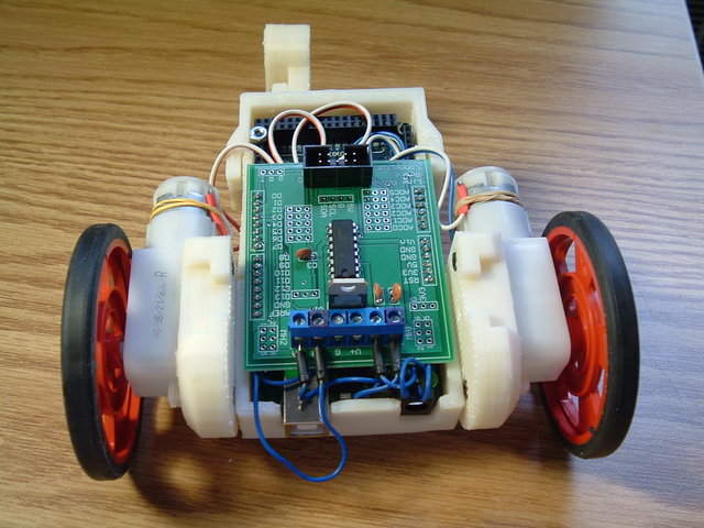
I’ve put off working on my LED calculator project for far too long, at first trying to find the right handheld case to put it in and then later hoping to be able to manufacture a case myself. I’m not having any luck with that right now and if I keep waiting I’ll wait forever; so I’m resurrecting the project with the intention of selling it as a kit sans case.

The idea is to expand on a simple LED tester by allowing the user to plug in an LED, dial in the LED brightness, and then read information on an LCD showing the LED voltage drop, the current current, and the value of current-limiting resistor to use in a target circuit.

A microcontroller determines this information by measuring the voltage drop across a series current-sense resistor to calculate the current and measuring the voltage drop across the LED to calculate how much voltage will drop across the current-limiting resistor in the target circuit and what that resistor value should be.

Variable Resistor Drive

LED calculator drive circuit

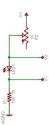
Until now, all of my prototyping has used a variable resistor in series with the LED to set the current. After subtracting the LED’s forward voltage drop from the supply voltage, the variable resistor dominates the resistance of the remaining series chain (which includes the current-sense resistor), thereby setting the series current.

LED calculator prototype with direct potentiometer drive

This does give control over the LED current and brightness, but the problems with this method are:

  • A small-valued potentiometer doesn’t provide enough resistance to dial down to low enough LED currents. For example, a 1K pot with the circuit running on 9V won’t deliver less than 6mA, depending on the LED color (and voltage drop); and modern, high-efficiency LEDs are surprisingly bright at 6mA.
  • A large-valued potentiometer has an extremely non-linear current response, with all the “action” at the very end of its rotation.

Here’s the response of two different LEDs with a 10K potentiometer:

Position Green LED Current Blue LED Current
0 1mA 1mA
1 1mA 1mA
2 1mA 1mA
3 1mA 1mA
4 1mA 1mA
5 2mA 2mA
6 3mA 2mA
7 4mA 3mA
8 5mA 6mA
9 34mA 21mA
10 100mA 89mA

Very slow response until near the end of the potentiometer’s rotation, at which point the response is so rapid that it’s very difficult to control
And of course this makes sense, as it’s the hyperbolic curve of I = V/R.

Transistor Drive

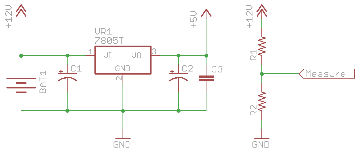
Last week I started looking at improving the range and linearity of the LED current. I’m not looking for a perfectly flat response curve nor for a true constant-current drive; I just want a somewhat better response. What came to mind was this simple PNP transistor circuit — actually an even simpler version without R1 and R3, but I’ll explain their purposes in a bit.

Transistor LED current control circuit

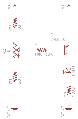
The theory is that R2 (or R1 + R2 + R3) acts as a voltage divider across the power supply, linearly setting a drive voltage. R4 (nearly) linearly turns this voltage into a current sink across the PNP transistor’s emitter-base junction; and because R4 >> R2, R2 presents a “stiff” voltage source to R4, meaning we can largely ignore R4′s effects on the voltage division.

Thus R2 provides (nearly) linear control of the emitter-base current. In the common-emitter configuration, the PNP transistor amplifies the current by the transistor’s β (about 150-200 for a small, general-purpose PNP like the 3906) for a correspondingly higher emitter-collector current

IEC = β IEB

which goes through the LED and the sense resistor, providing (nearly) linear control of the LED brightness by turning R2.

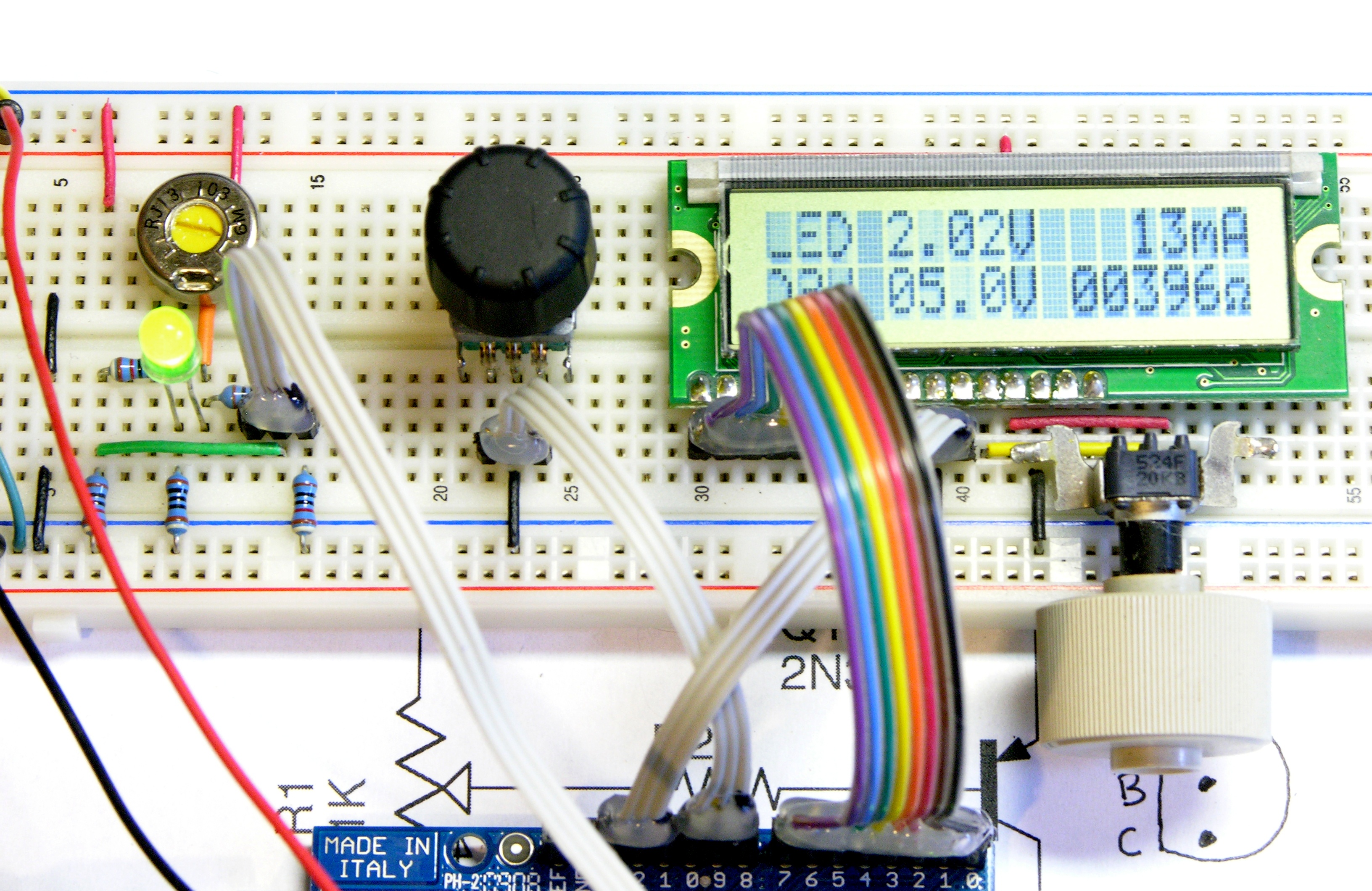
Well, that’s the theory, anyway. This weekend I dug out the prototype and built up the transistor control to test it in practice.

LED calculator prototype with transistor current drive

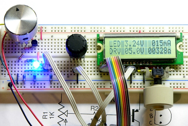
(70s decor courtesy Radio Shack.)

The first thing I noticed was a section at the CCW end of R2′s travel in which nothing happened, because R2 wasn’t providing more than the transistor’s cut-in voltage — that is, although VB was less than VE, it wasn’t enough less to overcome to emitter-base forward voltage drop and bias the transistor down into the active region.

I tried installing a small-signal diode “above” the potentiometer so that VB would always be at least .6V below VE and eliminate R2′s dead region, but the diode’s forward voltage drop was a little too high (it did too good a job) and the resulting minimum LED current was a little higher than I liked. I settled on adding R3 in that position, selecting 68Ω as a value that worked well with both traditional and high-power / high-efficiency LEDs and with both 9V and 7.2V supplies.

With a 9V supply and R3 = 68Ω, I tried three different values of the base resistor R4.

R2 Position R4 = 10kΩ R4 = 22kΩ R4 = 47kΩ
Green Blue Green Blue Green Blue
7:00 0mA 0mA 0mA 0mA 0mA 0mA
8:00 0mA 0mA 0mA 0mA 0mA 0mA
9:00 8mA 7mA 3mA 2mA 1mA 1mA
10:00 30mA 30mA 15mA 13mA 7mA 6mA
11:00 46mA 42mA 24mA 22mA 13mA 11mA
12:00 56mA 47mA 34mA 32mA 17mA 17mA
1:00 60mA 48mA 42mA 40mA 24mA 22mA
2:00 62mA 49mA 49mA 44mA 29mA 26mA
3:00 62mA 49mA 53mA 46mA 32mA 30mA
4:00 63mA 49mA 55mA 47mA 34mA 31mA
5:00 63mA 49mA 55mA 47mA 34mA 32mA

The table shows a similar effect at the other end of R2′s travel in which the LED current was pretty well maxed out and not increasing any further. I think I was hitting the knee between the transistor’s linear region and saturation, meaning increasing IEB was no longer increasing IEC. Experimentation gave me R1 of 200Ω keeps the transistor pretty well out of saturation and gives a satisfyingly more-linear response than what I measured here.

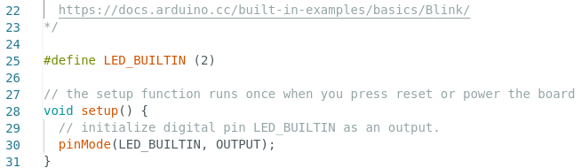
The 0mA readings at the beginning of the table, by the way, are a bit deceptive — some of my test LEDs are actually lit in that region. I’ve updated the Arduino code to show tenths of a milliamp when the reading is below 10mA, and I can see LEDs glowing with as little as .1mA. Probably not a value of interest for most people, but it could be effective for making flickering gas lamps for model railroads.

Choosing Values

R4 = 22kΩ looks like a pretty good compromise between providing a near-linear response and covering the range of LED currents I expect most people would be interested in testing, so I’ve tentatively settled on it.

I’m still fiddling with values to give good performance at both 9V (alkaline battery) and 7.2V (NiMH), because I use rechargeables almost exclusively and want to make this work well on rechargeables to encourage other people to do the same. The problem is,

Vsupply = 7.2V
VEC ≈ .8V
Vblue LED ≈ 3.5V

VR5 = Vsupply – VEC – VLED = 7.2V – .8V – 3.5V = 2.9V

ILED = IR5 = VR5 / R5 = 2.9V / 100Ω = 29mA

In other words, running on a 7.2V battery, with the transistor saturated, a blue LED with a 3.5V forward drop maxes out at 29mA; and it gets worse with a battery that’s not straight out of the charger and some white LEDs with a higher forward voltage drop. I’d like to enable people to test up to 50mA, to cover high-brightness LEDs, so I’d like to push this maximum current a little higher.

R5 = 68Ω gives ILED up to about 42mA, which isn’t as high as I like; but the tradeoff is that a smaller R5 gives me a smaller voltage range to sample in the A/D converter, hence lower resolution for the display. 68Ω seems like a good compromise. And I’m already thinking about a DPDT switch to change the resistor and alert the microcontroller about battery chemistry.

Rutgers Student’s CupCaked Robot Chassis

Monday, November 23rd, 2009

Rutgers student's RepRapBot Mrk II

Being able to do things like this is why I bought a CupCake. via Make

Calibrating the CupCake Part 1: Nozzle Temperature

Friday, September 11th, 2009

Measuring width of Spam can at grocery store

Last Saturday I went shopping for lunch with a tape measure.

Frying Spam for lunch

Delicious Spam™, fried up nice and crisp and served with Grannie’s “homemade” [what exactly does that word mean?] mustard. Yummmm!

The behavior of my CupCake during the first week of testing and parts-building had made me think that the nozzle was actually colder than the extruder controller believed it was — barely able to push plastic at allegedly 220°C and much happier at 230°C with not much scorching.

MakerBot CupCake plastruder with nozzle in water

I had previously cross-referenced the extruder’s reported temperature with my infrared thermometer’s reading at room temperature (which I no longer trust) and had dipped the heated nozzle into a small pool of water to try to find the boiling point.

Condition Thermometer Measured Thermometer Converted Thermistor Reported
room temperature 68°F 20°C 16°C
dipping nozzle into water and adjusting set temperature until water boils 105°C

In the 100-115°C range, the water would sizzle when the nozzle heater was on and stop boiling when it was off. It boiled most evenly between heating and cooling at a reported 105°C, so I was guessing that it thought 100°C was really 105°C.

This turned out to be incorrect; but it convinced me to perform a more proper thermal calibration, which is what counts.

(more…)

Programming the CupCake Motherboard and Extruder

Wednesday, September 2nd, 2009

Because the (early batch) CupCake circuit boards are assembled by the customer (me), they’re unprogrammed and the customer (me) has to use an in-system programmer (ISP) to burn the bootloader and then an FTDI USB-serial cable and Arduino development environment to program the firmware. Happily, the prerelease kit included both a USBtinyISP and the necessary FTDI cable, so I was good to go.

I got the bootloader programmed into the motherboard just fine, but I couldn’t get the Arduino IDE to program the firmware into it (and yes, I did install the Sanguino support). The motherboard has a switch to signal the (PC ATX) power supply to turn on and feed all the peripherals; but it’s emphasized that standby power is always provided to the ATmega on the motherboard, so there were no steps needed to power up the ATmega for firmware download. Further, the motherboard power switch didn’t power up the power supply, so I figured it must not be needed yet.

But every time I tried to upload firmware, I kept getting a long timeout and:

Binary sketch size: 15002 bytes (of a 63488 byte maximum)

avrdude: stk500_recv(): programmer is not responding

as though the Arduinoness of the motherboard wasn’t there.

Lots of MakerBot forum posts identify the same problem and talk about jumpering the power supply cable to make it turn on.

C’mon, that can’t be for real. The programming instructions don’t say anything about needing to mess with your power supply cable, and that would be a massive omission.

Maybe another look at the motherboard power switch? Switching it didn’t make anything happen, and the schematic for my V1.1 motherboard shows that the power-on signal to the ATX power supply is under the control of Arduino digital pin 14 — a chicken and egg problem.

MakerBot CupCake motherboard with power supply jumpered for initial programming

After about an hour of searching CupCake and RepRap forums, poring over the schematic for anything I might have missed, trying different random things, and generally getting pretty good and angry, I gave up and used Wikipedia’s ATX power supply entry to help me jumper the power supply’s power-on lead. The power supply came on and the motherboard programmed on the first try.

You’re kidding me. This is a necessary step, it causes so much trouble that everybody posts about it in the forums, and it’s still not covered in the assembly instructions? I honestly still think I must be missing something.

Programming the MakerBot CupCake plastruder controller

Fool me twice, shame on me. When it was time to load firmware on the extruder controller, I found that leaving the USBtinyISP connected from the computer to the PC board’s ISP header is a great way to supply the microcontroller with power for the first Arduino firmware upload.

Yes, by this point the motherboard was correctly controlling the power supply; but this was a handy trick I need to remember.

SparkFun Tour

Sunday, August 23rd, 2009

At the end of July, I was traveling in the Boulder area and had the privilege of getting a tour of the SparkFun headquarters. I got my first Arduino from them; and although I’m not a terribly frequent shopper, I follow their blog assiduously and I love what they do, so it was a pretty thrilling experience.

SparkFun headquarters, exterior

SparkFun posts a lot of pictures on their site and they’re not shy about showing off their facility, but the online photos don’t give quite the same perspective on their operation that an outsider gets when coming through for the first time. They told me there was nothing I couldn’t photograph and post, so I wanted to share a bit from my tour.

(more…)