I’m trying to get my LED calculator out the door this summer, and that requires embedding an Arduino-compatible “core” into my own system. Yes, yes, I could use a microcontroller without the Arduino environment; but if I actually get this thing ready to sell, I want my customers to be able to reprogram it (apply firmware upgrades or enhance the feature set) in a comfortable environment. Hence an Arduino-compatible core.
I haven’t made an Arduino-compatible before, and the only two things I found daunting were the crystal, which I understand has to be exactly matched to its supporting capacitors or the circuit won’t resonate, so it was important to find the same one used in the Arduino; and the resettable polyfuse on the USB power lines, which doesn’t (in the Arduino circuit) specify whether 500 mA is the hold current or the trip current.
I found an Arduino playground post by Tom Igoe giving Digi-Key part numbers for a bare-bones breadboard Arduino-compatible and chased the out-of-stock crystal to the equivalent Digi-Key catalog number 887-1019-ND. I searched far and wide for information on the polyfuse and gave up, settling on 500 mA hold current, since that’s permitted (after negotiation) by the USB spec and surely we wouldn’t want to trip at the maximum permitted current.
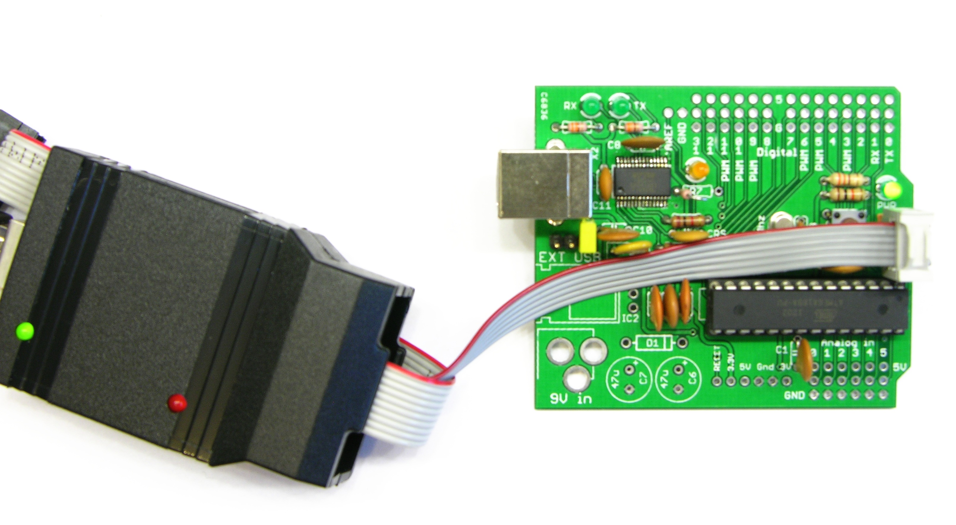
With that data in hand, I still had a healthy dose of uncertainty about my likelihood of building a working Arduino-compatible. I prefer to develop and test modularly, so I wanted to assemble a working proof-of-concept Arduino-compatible before diving into the LED calculator project. And as it happens, I had a perfect project waiting in the wings — an Arduino-compatible board with ground and power headers surrounding the normal I/O headers (like servo connectors), to make it easy to connect external sensors without going all-out and buying a sensor shield (which actually has the I/O pin at the end of each connector rather than in the middle, whatever). I want to build my own version of my friend Trevor’s household temperature-monitoring system, and such an Arduino-compatible would be a great platform for terminating the three-wire temperature sensors.
To speed the process, I started with the EAGLE schematic of the Freeduino through-hole design, ripping up the board and laying it out mostly from scratch to make room for my extra header rows. I had the board produced by BatchPCB, I received it last week, and I have now assembled it into a working Arduino-compatible.
But not — this is going to sound soooo familiar — without some snags along the way.
Testing the FTDI USB-Serial
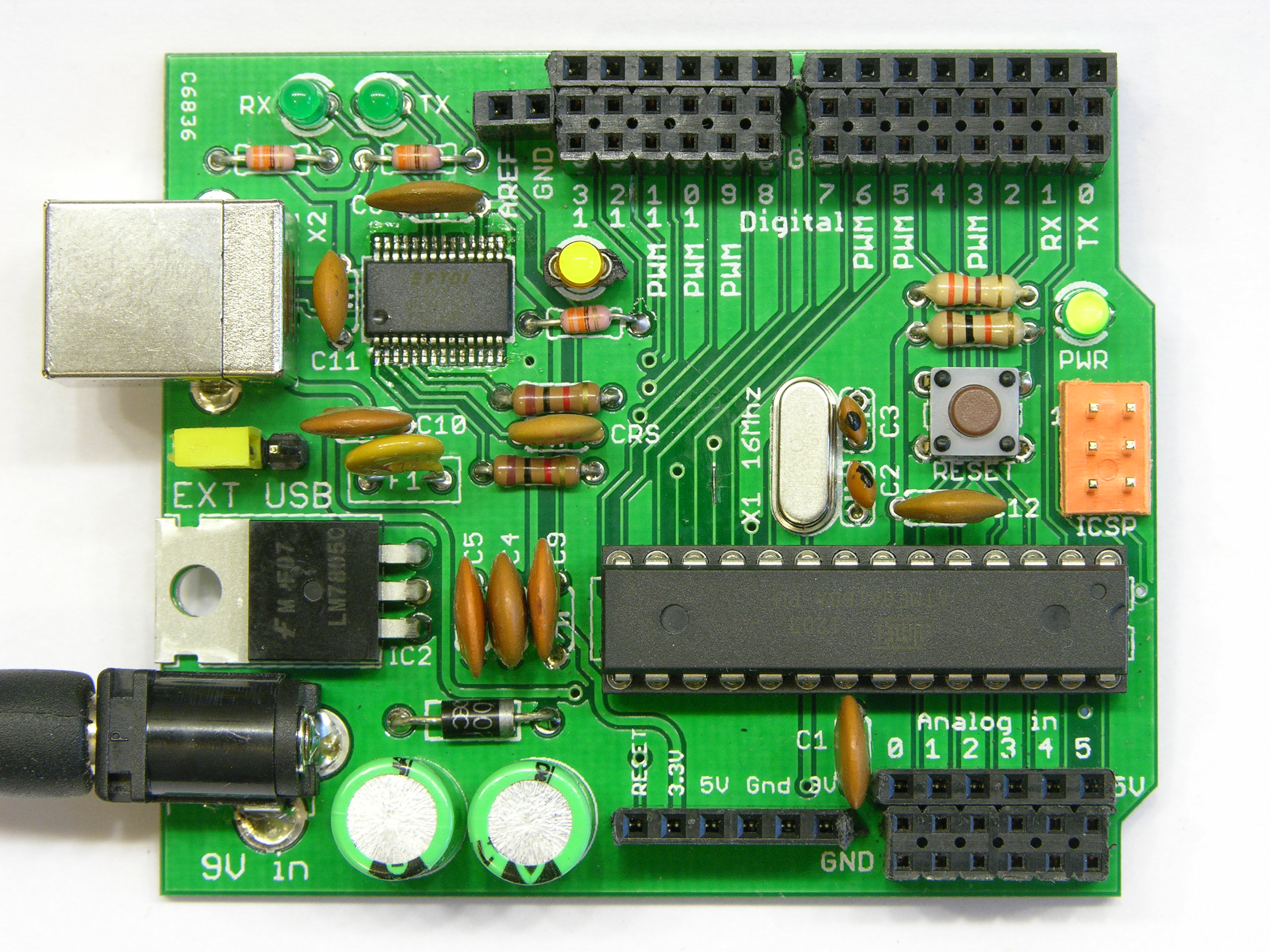
The one component not available in a through-hole package was the FTDI USB-serial chip; and I planned on hand-soldering it; and that’s way easier to do without other components looming over it and getting in the way of the iron; so I attached it first. And that led me to test it first as well, since I test as I go.
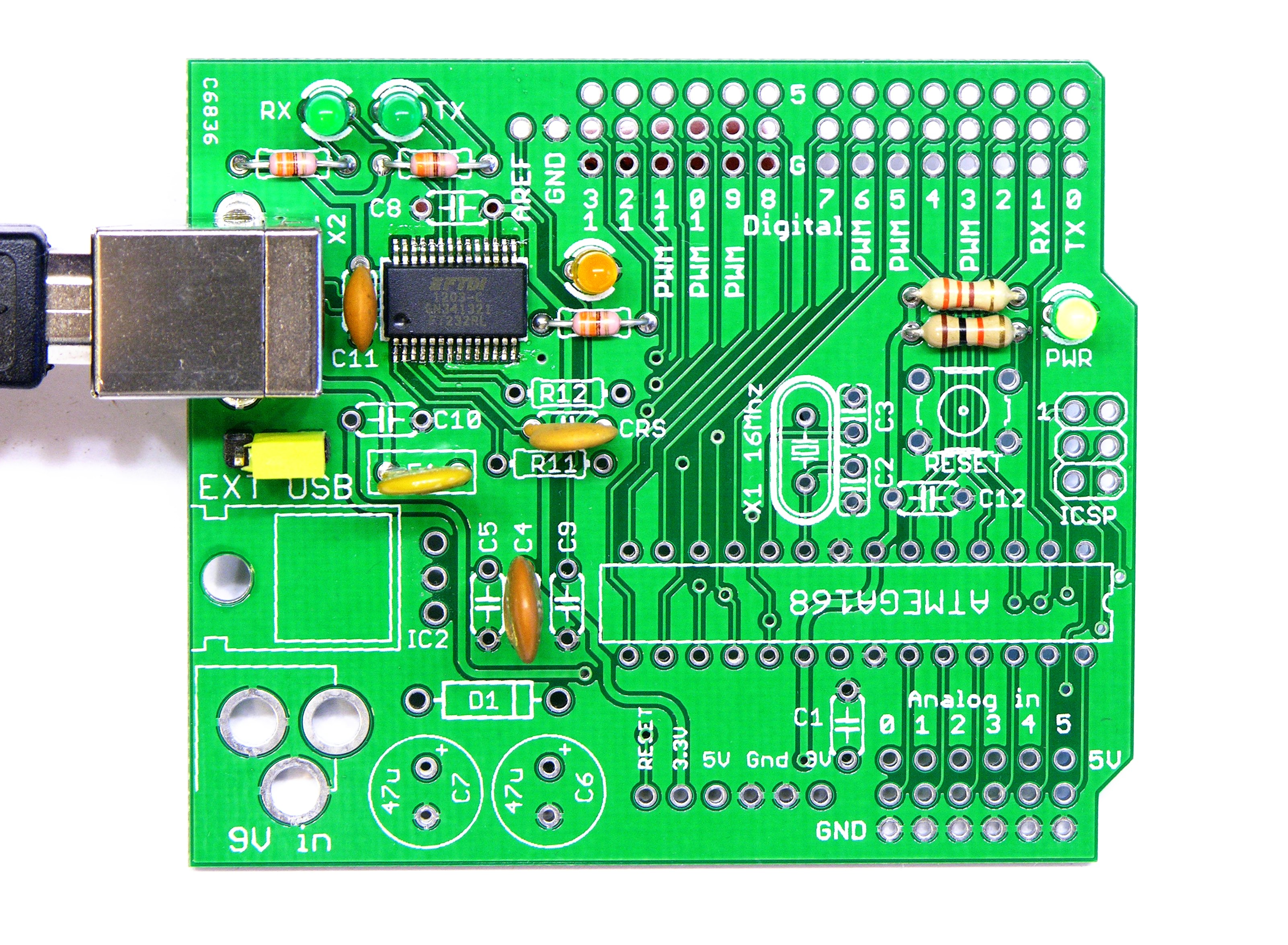
This is about the minimal set of components to test the entire operation of the FTDI chip. Power jumper and lots of bypass capacitors, polyfuse, power LED and current-limiting resistor, transmit and receive LEDs and resistors, and … yeah, the Arduino’s digital pin 13 LED is completely unnecessary.
And it worked! I powered it up first connected only to a powered external USB hub so that if anything was horribly wrong, there was no way it could smoke my computer. The power LED came on and the transmit and receive LEDs came on and stayed on. With only the slightest twinge of hesitation, I plugged it into my laptop. The transmit and receive LEDs went out, ZTerm recognized a new serial port, and I could type into the receive LED to my heart’s content.
ATmega and ISP Header
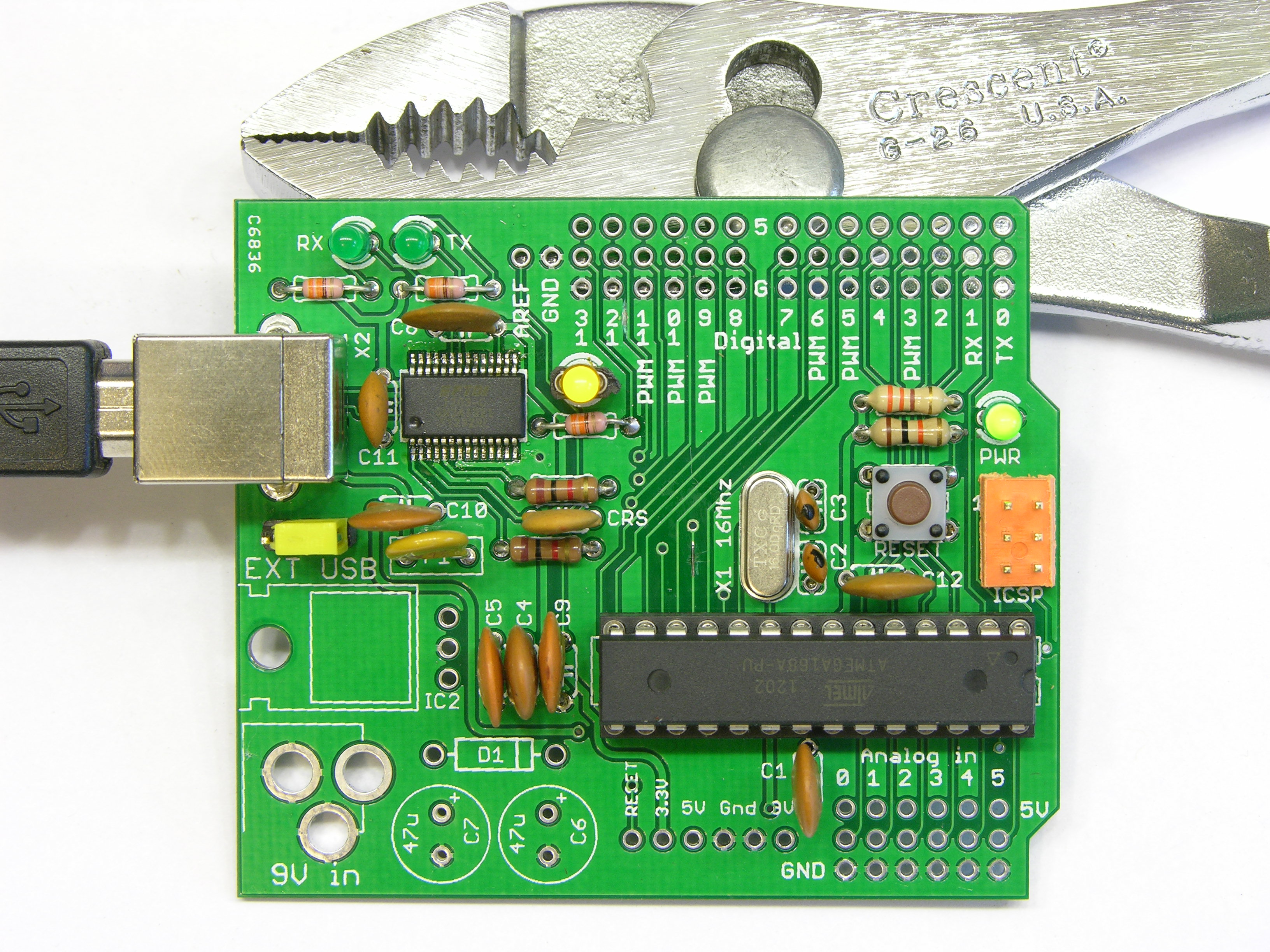
The next step was to install the microcontroller and try to in-system program it. The minimum additions were the ATmega and socket, the crystal and its capacitors, the reset button and pull-up resistor, and the ISP programming header.
I connected my USBtinyISP, fired up the Arduino IDE, and tried to burn the bootloader — and it didn’t work. The USBtinyISP thought it had no chip connected.
It was late Wednesday evening and I had to put the board away with the problem unsolved. I didn’t yet know whether the problem was with the microcontroller not even running, with the programming port, or somewhere else in the design.
Troubleshooting In-System Programming
Thursday night I had a rehearsal so didn’t get to devote much time to the problem, but I did move the ATmega from a working Arduino into this board and it worked, running the Blink sketch. I put the ATmega from this board into the working Arduino board and in-system programmed it, and it worked, both there and when I put it back into this board. That was a relief — it meant the fundamental design was okay and I had a problem with the programming port.
Which is so dead simple, how can it have a problem??? It’s just traces!
But one of the traces is both the ISP clock line (SCK) and the Arduino-compatible’s digital pin 13, which has an LED on it, which loads down the ISP clock line … I lifted one leg of the current-limiting resistor, but that didn’t fix it.
I spent Friday evening with friends making (and consuming!) pizza and ice cream, so it was Saturday before I got back to this. By then I had examined the schematic and board layout over and over again, comparing them to multiple other references for the ISP pinout, not finding any problems; and I knew I had to get more serious. It was time to learn to use my Saleae logic analyzer.
I love the product. I find the manual not well organized and I got no response to my polite email months ago detailing many, many ways they could make it more clear for me — such as listing what voltage range is considered logic high. I love the look of the user interface. I find manipulating the view and the data clumsy. I hate learning to use new products and systems when I’m in the middle of something hard I wish I didn’t have to do, and I learned anyway.
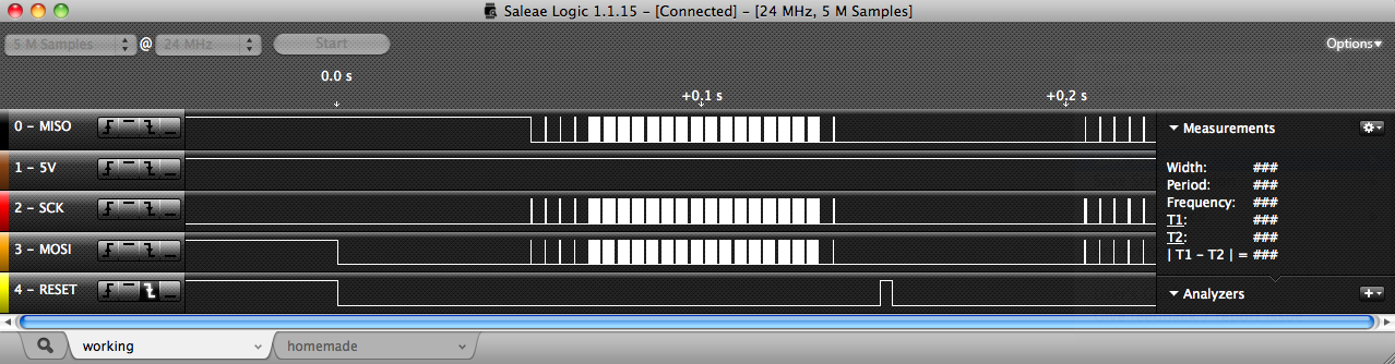
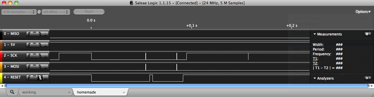
I connected the logic analyzer to every pin of the ISP port — including the 5V power pin, mainly for completeness but partly out of paranoia — of the working, real Arduino and set the analyzer to trigger on a negative-going edge of the RESET line (or assertion of /RESET, if you wanna be that way). I captured the beginning of an ISP cycle, then moved the analyzer to the homemade Arduino-compatible and repeated the capture. You may safely ignore the transitions on SCK before the trigger event (time 0.0) — the boards are running the Blink code until they get reset to start the programming (attempt), and that’s the LED pin.
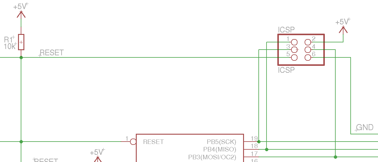
I saw enough differences between these captures that I wasn’t sure where to begin, so I decided to go to the source: Atmel’s application note AVR910P In-System Programming. I verified the ISP port pinout yet again. I read about the functions of each pin. And on page 4, I found this gem:
When Reset is applied to the target AVR microcontroller, the MISO pin is set up to be an input with no pull up. Only after the “Programming Enable” command has been correctly transmitted to the target will the target AVR microcontroller set its MISO pin to become an output. During this first time, the In-System programmer will apply its pull up to keep the MISO line stable until it is driven by the target microcontroller.
Hang on. MISO is set to be an input and the ISP will apply a pull-up? Then why, on my board, is it low the entire time? It must be shorted to ground.
I grabbed the meter. MISO was shorted to ground.
AWESOME! I just have to find the solder splash … which is unlikely on a commercially-produced board with solder mask … and there’s no solder splash.
Okay, I just have to find the design error connecting MISO to ground. Yeahno, EAGLE absolutely has MISO and GND as separate signals. And BatchPCB sent me a spare copy of the board, which I checked with a meter, and which did not have MISO shorted to ground.
Okay, I just have to find the manufacturing error shorting MISO to ground. Many, many minutes with a magnifying glass and I found nothing.
The whole time I’m thinking about how glad I am it’s a two-layer board so I don’t have to be paranoid about a short on an interior layer where I can’t see it.
Yesterday ended and I went to bed knowing I had a signal shorted to ground and being completely unable to find it.
Today I knew I had to get yet more serious. Out came the Capacitor Wizard.
Scoff all you want. It has saved me countless hours testing capacitors in-circuit, but its utility doesn’t end there. It is an exquisitely sensitive ohmmeter and can easily detect the difference in resistance between 1″ and 2″ of copper trace.
I put one probe on the ground plane and tested every point along the MISO path with the other probe. The short to ground was quite clearly nearest the header at the top of the board.
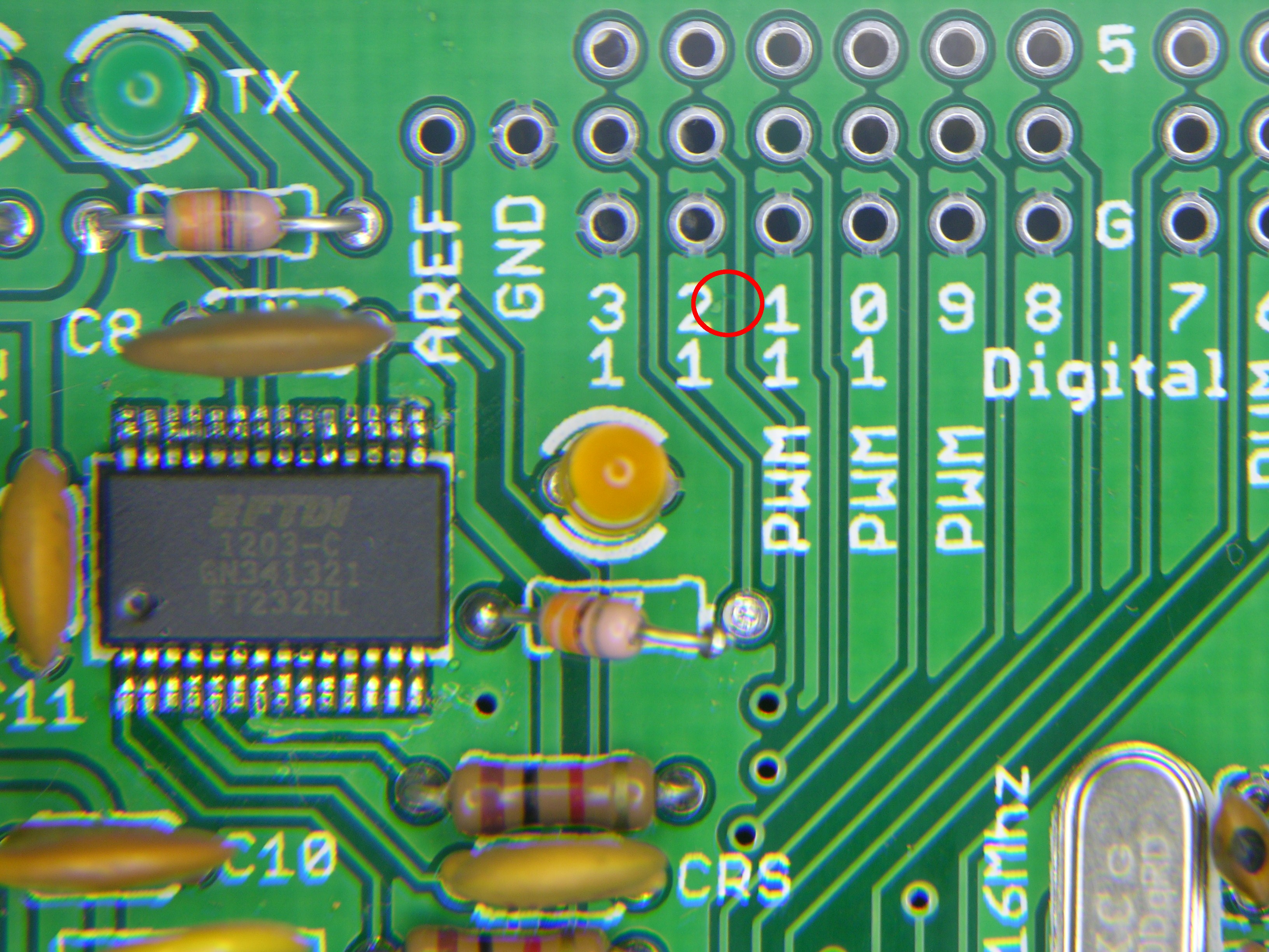
Back to the magnifying glass, and knowing where to look, I found this. (As always, click to see full resolution.) It looked like a booger in the varnish, but it extended across the isolation between the ground plane and MISO, and it was in the segment of the MISO trace where the Capacitor Wizard said it should be.
I took the board to Ron’s to use his big magnifying glass to get the pic, and he was convinced the booger wasn’t in the copper layer and didn’t want to scratch up my pretty new board finding out, especially after knocking down the surface of the booger with a plastic scratching stick and not getting down to copper. He even desoldered the microcontroller socket to get a closer look at its pads and the vias under the socket … finding nothing, of course.
So when he stepped out of the shop for a bit, I cut the MISO trace near the microcontroller to isolate which end of the trace had the short to ground — and it was the upper end. Armed with that information, Ron couldn’t help but capitulate. I allowed him the honor of scraping away the “hair” for me, which quickly revealed itself as copper, and he quickly revealed a few words he knew. And the short was gone.
Ron did a gorgeous, almost invisible job of jumpering over the trace I had cut. MISO was still not shorted. I brought the board home and resoldered the socket and MISO was still not shorted. I tested the ISP. It now works fine with the digital pin 13 LED out of circuit and it doesn’t like the load with the LED in circuit.
No problem. For my prototype board, I socketed the ancient, power-sucking LED so I can remove it if ever I want to in-system program the board again. Inside my LED calculator, I probably won’t put a “Blink” LED. If I want to make a board that does have an LED on digital pin 13, I’ll buy a modern, high-efficiency LED that I can run with a much higher series resistance, just like the real Arduino does, and not load down the SCK pin so much.
Sweet, Sweet Success at Last
A little more soldering to install the headers and the rest of the components, and that’s the rest of the story.
Well, almost.
To quote SparkFun forum user FlorinC, talking about an entirely different board,
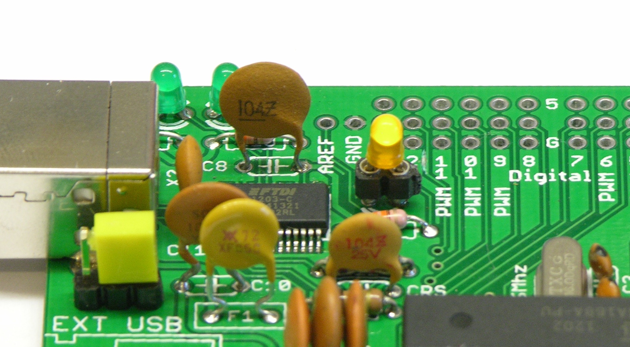
The capacitors look taller than the headers. This will be a problem when a shield is plugged in.
<scratches head> Yup. Ya got me there. Good thing I built this one specifically to avoid using a shield.
But well noted. I’ll use leetle capacitors should I decide to make an Arduino-compatible into which I intend to plug a shield.
Nice diagnostics, I followed most of that. What is the cost difference between making your own board vs buying a ready made one?
Andy, I haven’t done the math yet, but this is not a way to save money, at the relatively small quantities of components I bought. By way of perspective, the PCB from BatchPCB cost me $17 (and I estimate it’d cost $10 from Gold Phoenix in their standard panel sizes); the FTDI USB-serial chip is about $4 in modest quantities; the ATmega (and note that I used an older one) is a little under $3; etc. I have easily as much money in components as the cost of a ready-made Arduino.
Was just curious to know, depending on how well my current arduino project goes, I might get some more.
If you are going to use this as a core of a product, it make sense that you know how to analyse it.
Cheers,
Andy
This a great example of CSI: PCB. Very useful lesson to see how subtle etching flaws can get.
Great troubleshooting!
Quote:
“the crystal, which I understand has to be exactly matched to its supporting capacitors or the circuit won’t resonate”
I have always just used a pair of 22pf caps to ground across the XTAL pins, just used any 16 mhz crystal, and have never found them to not resonate. In my opinion, they are not very sensitive at all to wrong load capacitance or type.
(feel free to correct me on this, just my experience)