After receiving some encouragement, I went ahead and breadboarded the measurement circuit for the LED calculator. Someone may suggest a better way to do it, but here’s what I’ve been carrying around in my head:
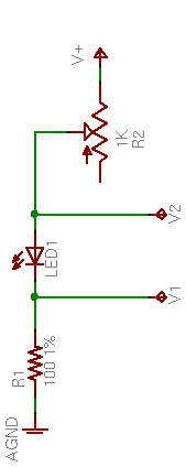
R2, a 1KΩ potentiometer used as a variable resistor, controls the LED brightness. R1, a precision 100Ω resistor, limits the maximum LED current and acts as a sense resistor.
By measuring V1, we can calculate I1 = V1 / 100Ω. Since ILED = I1, we’ve determined the LED current. And VLED = V2 – V1, so we can determine the LED voltage drop as well.
The value of R2 isn’t critical. With a supply voltage of 9V and a very low LED drop of 1V, a 1KΩ variable resistor allows us to test LED currents down to (9V – 1V) / (1KΩ + 100Ω) ≈ 7mA, which is probably low enough for most applications. To be able to test lower, increase the range of R2.
Test Measurements
I built this much of the circuit and took measurements of a few different LEDs at a few different brightnesses, to make sure the potentiometer would really work the way I expected, and that I hadn’t made any stupid mistakes in the voltage calculations.
| Color | V1 | V2 | VLED | ILED | |
|---|---|---|---|---|---|
| green | .71V | 2.70V | 1.99V | 7mA | |
| 2.00V | 4.04V | 2.04V | 20mA | ||
| 3.45V | 5.55V | 2.10V | 35mA | ||
| red | .73V | 2.55V | 1.82V | 7mA | |
| 2.00V | 3.88V | 1.88V | 20mA | ||
| 7.28V | 9.24V | 1.96V | 73mA | ||
| blue | .61V | 3.61V | 3.00V | 6mA | |
| 1.12V | 4.23V | 3.11V | 11mA | ||
| 2.00V | 5.27V | 3.27V | 20mA | ||
| 5.56V | 9.24V | 3.68V | 56mA |
The measurements make sense — each LED’s forward voltage drop increases slightly as the current increases. If I remember my semiconductor theory correctly, that’s called the ohmic region of operation, in which a diode behaves like a very low-valued resistor.
Automating the Measurement
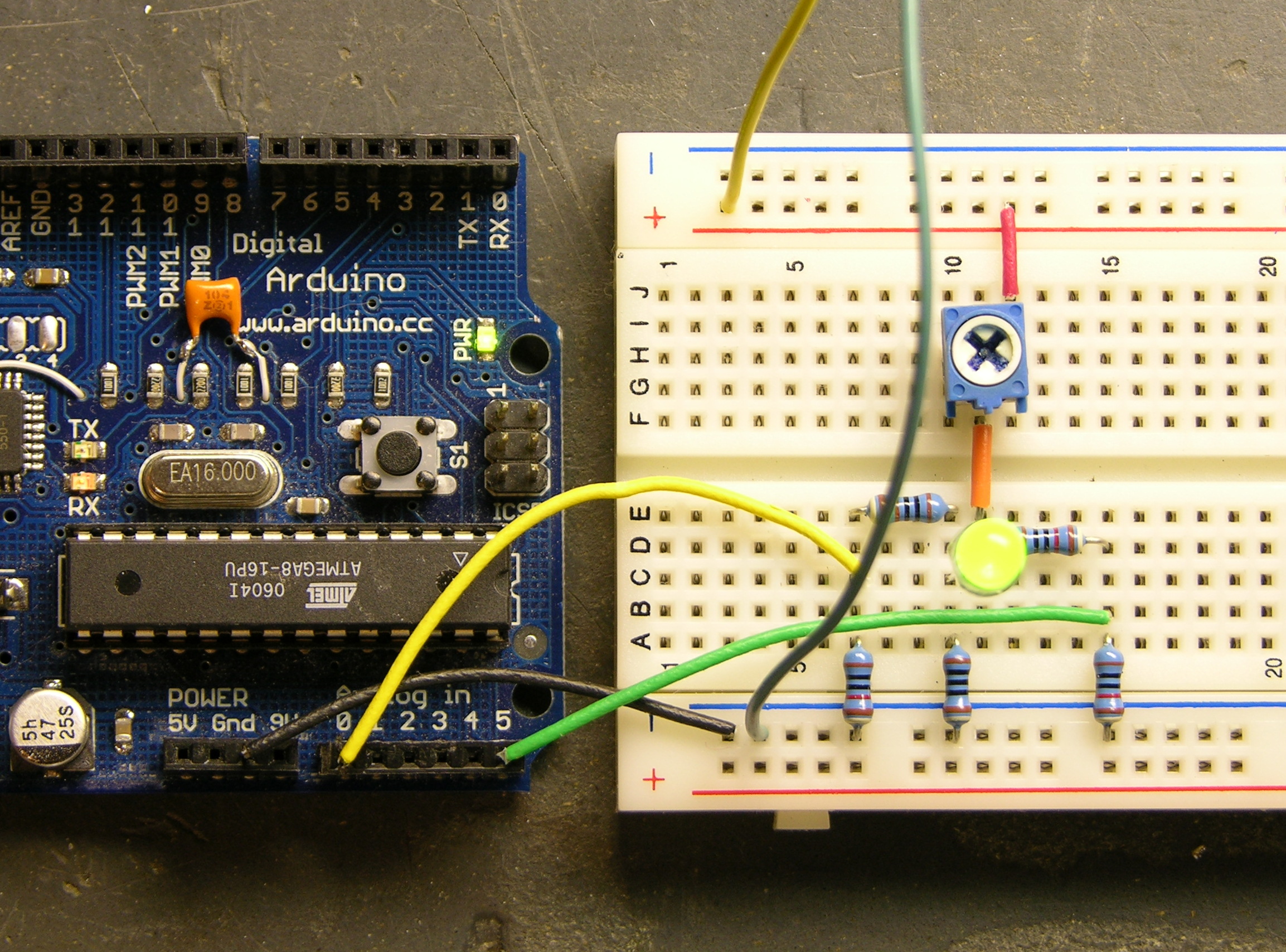
In a self-contained LED calculator, the voltages will need to be read by a microcontroller, which will also drive an LCD. For now, I used my Arduino and had it send results to the host computer.
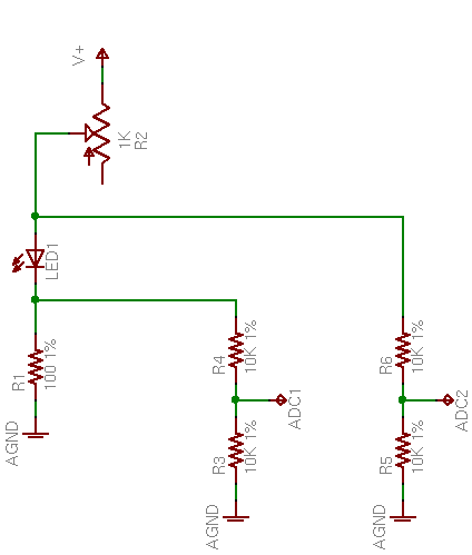
Depending on the position of potentiometer R2, V2 can range up to the supply voltage of 9V (or whatever); and V1 can range up to the LED’s forward voltage drop less than that. I’m pretty sure the microcontroller’s A/D converters don’t like inputs over 5V, so I needed to divide V1 and V2 to lower their ranges before feeding them into the ADCs. I used two pair of precision 10KΩ resistors for that.
All put together on the breadboard, it looks like this.
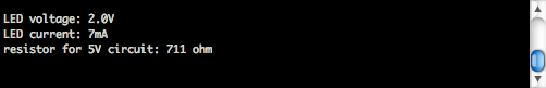
And with a little Arduino program running to read the inputs, scale from 1024 steps back up to a range of 5V and then double to compensate for the voltage division, and calculate all the values, I get this.
Putting It in a Box
I’ll probably program an Atmel chip directly, because I don’t need all the USB baggage. Even a Boarduino has prototyping parts on it that I don’t need here.
I need to think carefully about the LCD screen, to have enough room to display all the information and still be small enough to fit into a reasonable project box. A cell phone screen would be the perfect form factor, but really drives up the cost and complexity. I think about a 4×16 character display would be okay; 4×10 would be tight for the text and I’m afraid 4×20 would be too wide for the box.
LED 2.10V 35mA
DRV 8.4V 180ohm
Okay, 2×15 is a bare minimum. All Electronics has a 2×16 module that’s 4″ wide and another that’s 3.15″ wide, which suggests having to build the calculator in landscape mode. Not wild about that. Digi-Key has 4×16 starting at $27 and — hey! — a comparatively svelte 2.6″ wide 2×16 at $5.88.
I breadboarded something like this recently. If you’re willing to add an op-amp (and a transistor, if the op amp can’t source the currents you want to test at), you can make the LED driver a voltage-controlled current source, which may give you more useful resolution out of a linear potentiometer.
I was interested in getting even more resolution at low currents (mostly out of curiosity), so I also added a couple of diodes to get a nonlinear current function of voltage with more resolution at the low end. The exponential characteristic of the LED is exactly wrong for this: we want the controlling signal to be something like log(current), not exp(current), so you need either a double log conversion or a current source + log converter.
In a darkened room, I had enough control at the low end to measure LEDs turning on somewhere around a tenth of a milliamp.
Have you considered giving the AVR control of the current? Since it’s a DC signal, you can do simple D/A by just aggressively low-pass filtering a PWM pin (or two, for more resolution). You could then have the AVR sweep through the desired current range and graph the voltage/current characteristic, or automatically read out your voltage and resistor combinations at some predefined currents (say, 5, 10, 15 mA).
Another useful attachment would be a photodiode or phototransistor, so you could match LEDs for a display application. You could use it to bin LEDs by brightness at a specific current, or to select customized resistors for each LED. You don’t need photometric accuracy if you’re matching the same kind of LED, just repeatability.
If you’d like to fit the whole under a 5V supply, you can use a small current-sense resistor and the differential ADC mode of a more recent AVR (like the 261) which has a built-in selectable gain stage.
Maybe you shouldn’t listen to my “feature creep” encouragement, though; I managed to convince myself to put my own version of this project on the back burner by adding too many features.
Keith,
Make sure your pot can handle the load you are putting on it.
LED’s drop 2 or more volts depending on the type. Your math was using 1V for LED drop.
David, I’m not sure which math you’re saying was using a 1V LED drop. All of the calculations here are using the actual measured drop of the LED.
“The value of R2 isn’t critical. With a supply voltage of 9V and a very low LED drop of 1V, a 1KΩ variable resistor “
Keith,
I just posted up an article about an adjustable current sink that might be helpful with respect to your LED tester idea. Let me know if I can help you with this project.
http://www.uchobby.com/index.php/2008/02/03/adjustable-current-sink/
David, the comment about the value of R2, the variable resistor, is to demonstrate that even in a worst-case scenario with a high supply voltage and an unrealistically low LED voltage drop, the 1KΩ variable resistor is large enough to test down to a relatively low LED current of 7mA.
All of the calculations of actual LED current use the actual measured LED voltage drop.
It might be interesting to plot out some infrared (both near IR and far IR)
LEDs, and an ultraviolet LED.
For some advanced mathematics, can you correlate the forward voltage with the colour (e.g., band-gap energy of the semiconductor versus the
wavelength of operation).
Also, does the I-V characteristics depend upon ambient illumination? How about self illumination (e.g., holding a reflective mirror in front of the LED
to reflect its own light back into it).
How does temperature affect the I-V characteristics?
Anyway, just some fun things to think about.
Dave