Speaker Power Detector
A visitor to my blog posted a comment asking:
I’d like a device that connects inline to the speaker output(s) on my home stereo amplifier between the amp and the speakers that has led indicators that flash with the audio signal that passes through the speaker wire.
We have outdoor speakers on our “B” channel of the amp. On many occasions, we forget to turn them off, and I’d love some type of indicator that would be on/flashing when the speakers are in use. This would remind us to turn them off.
Any ideas how to build a device like this, or somewhere to go?
It seemed like an interesting request, potentially useful to other folks, and easy enough to build. I’ve put together a prototype, and the following pages explain how it works and how you can build one for yourself. If you want to make one, I’d suggest reading through the entire set of instructions before beginning.
One more thing. Right now, if you have an unusual amplifier or if you wire your amp incorrectly to the power detector project, you could short out your amp’s power outputs. Before building the project, use a continuity tester or ohmmeter to make sure your amp’s black (ground) speaker connections are tied directly together (< 1Ω resistance) inside the amp, and make sure you wire the amp to the power detector correctly. I'll work on a revision that's more forgiving of operator error.
Wait for the Revision
After conversation with a very helpful reader, I want to state this even more strongly: Don’t build this project on anything other than a breadboard just yet.
I need to redesign the input section to make it idiot-proof. I’m not even talking about you, gentle reader, but rather your two-year-old niece wandering behind the stereo, turning the knob, and making things go poof. Or your roommate moving the stereo and failing to pay attention to the polarity of the wires. Or any number of other things.
I’ll redo it with a high-voltage, balanced input that’ll work safely with any input wiring. It’ll probably be November before I can get to that.
If you want to play with the circuit before then and you’re prepared to be very careful with your amp, that’s great! The output section will still work the same, so you can get used to what it’ll look like. And the new version will still use the LM339 and most of the same parts.
But if you want to build one on a PC board to stick into a box and use, please wait. It’ll be worth it, for the added security of knowing it’s foolproof.
On to the Project
With that caveat in mind, feel free to read through the design and construction of the circuit.
Part 1: Schematic and Operation
Part 2: Parts and Enclosure
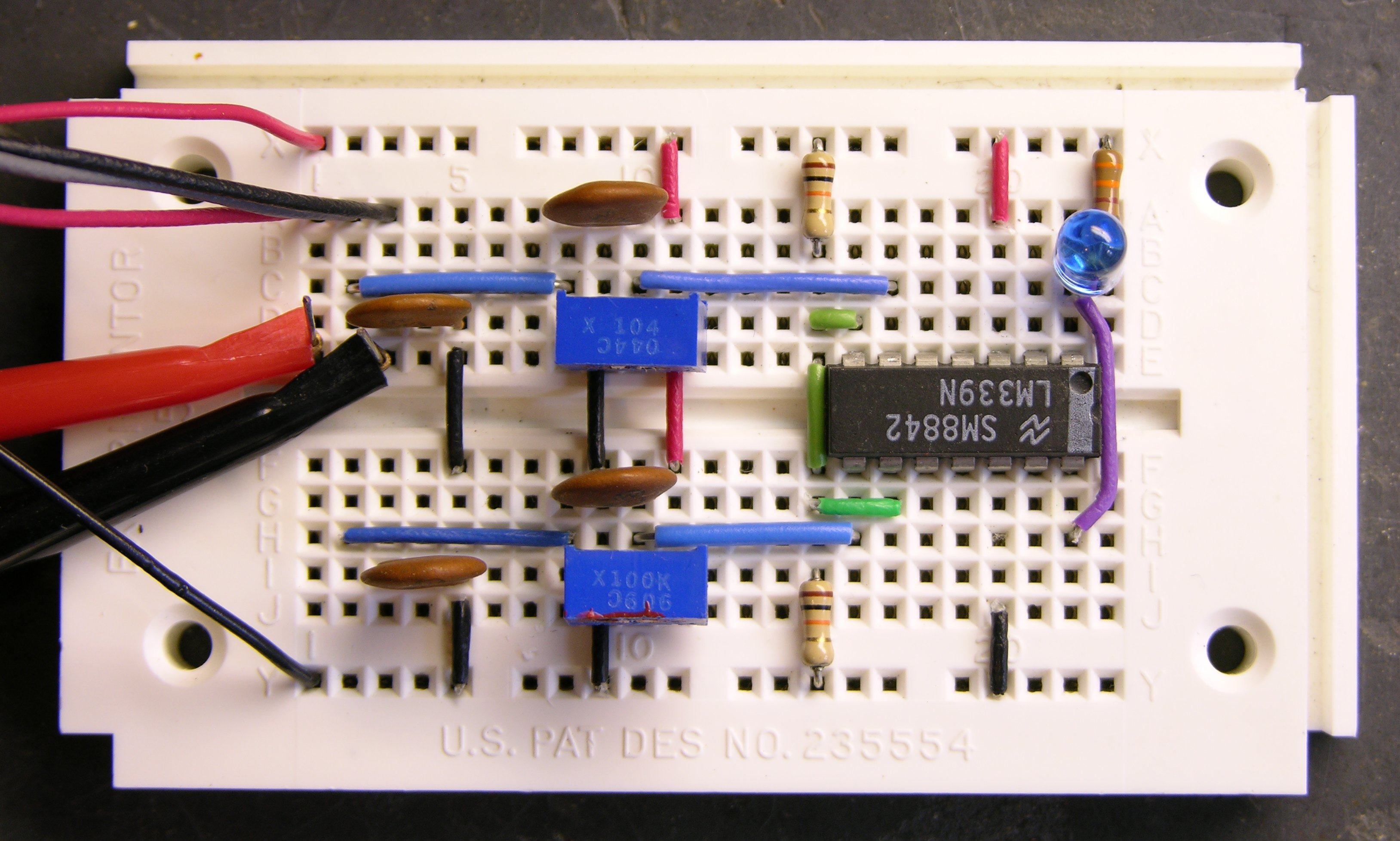
Part 3: Layout and Prototype
Part 4: Construction and Calibration
My blog software doesn’t allow comments on “pages” (like this); so if you have feedback, please go to my related post and add a comment.