Archive for November, 2021

Voron 2.4 Build — Fysetc Custom Parts

Friday, November 26th, 2021

Fysetc drag chain for Voron 2.4 3D printer

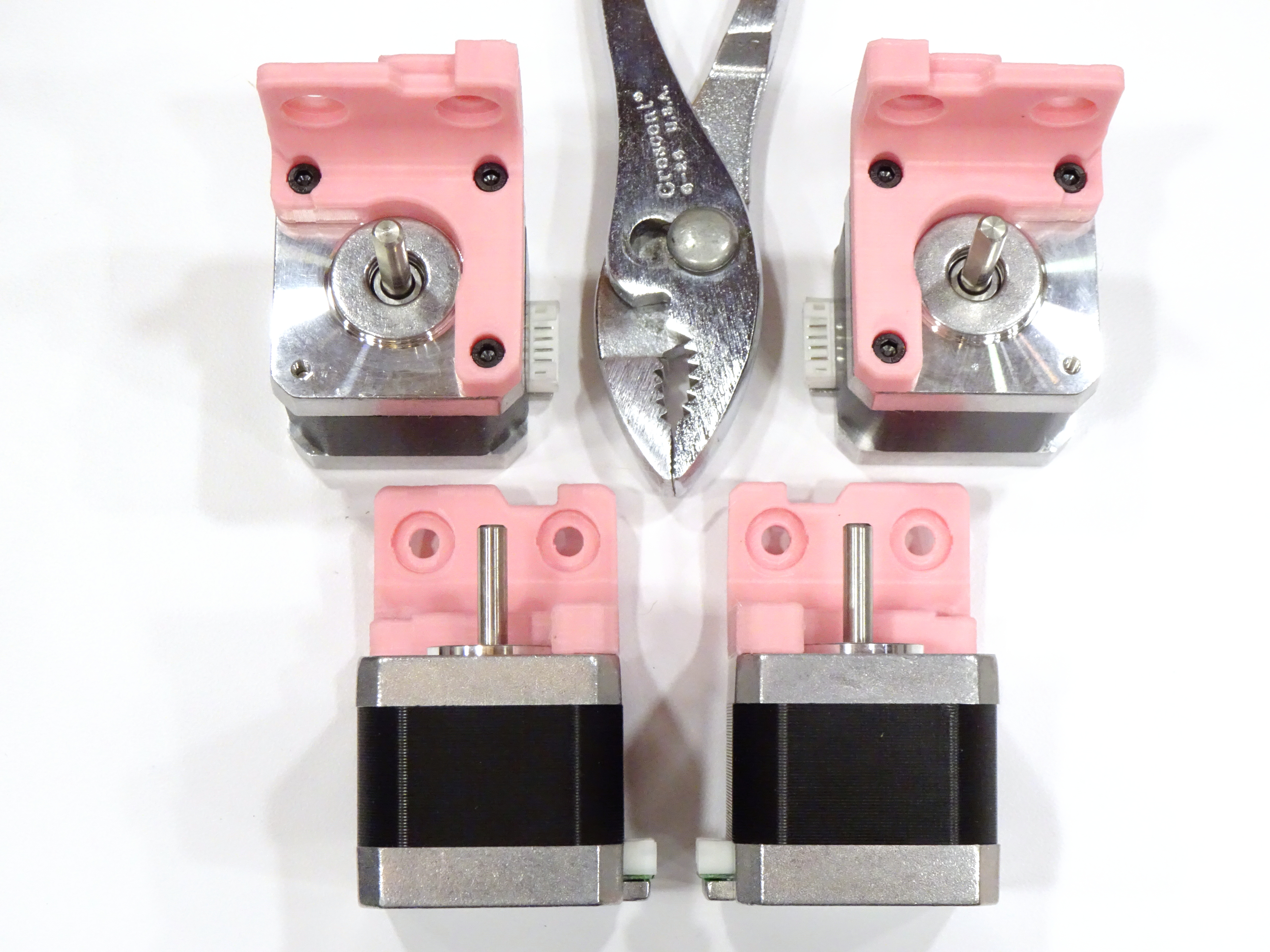
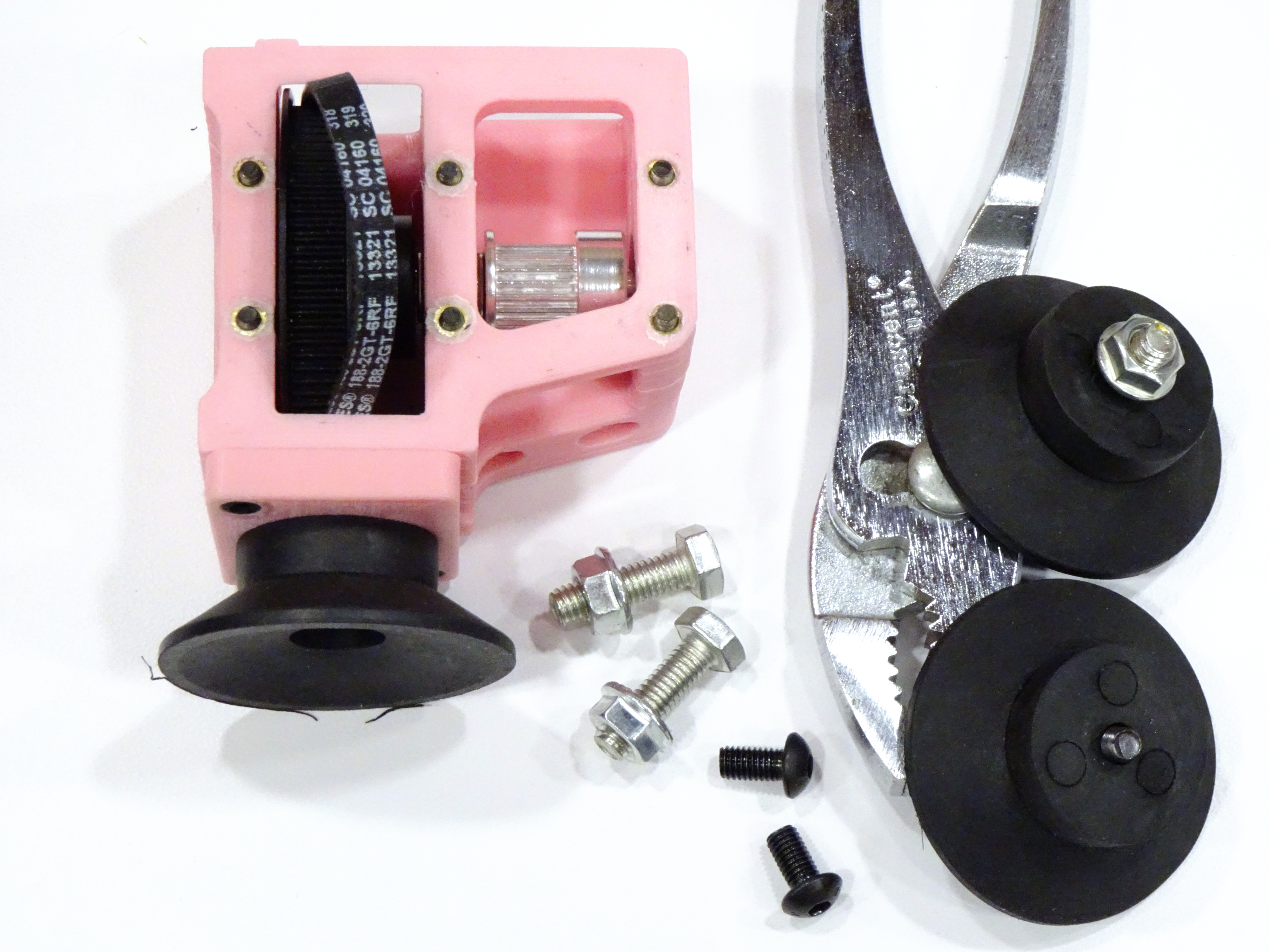
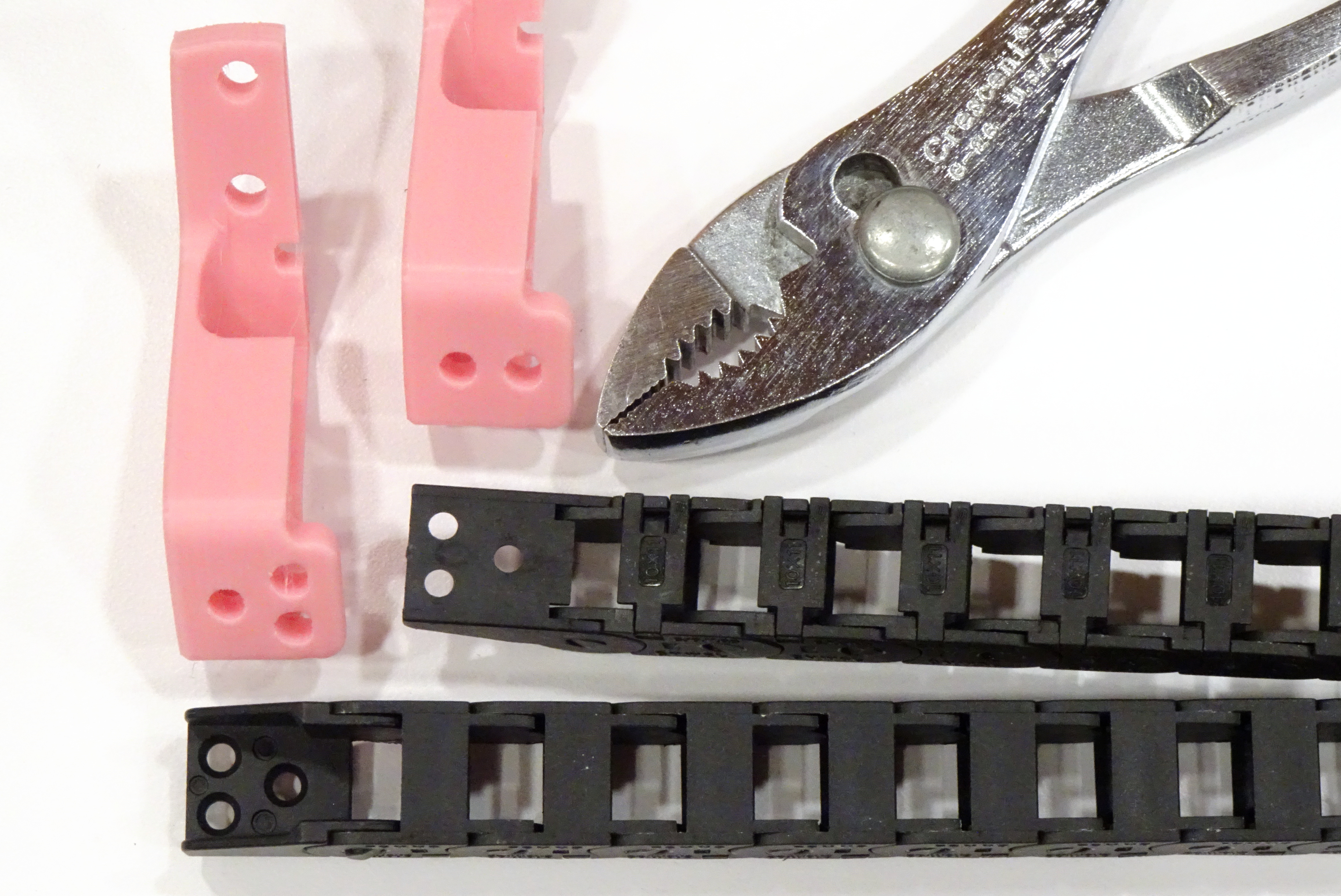
At the time I purchased my kit and at the time I printed my parts, the Fysetc bill of materials for the Voron 2.4 kit listed the specific part number of Igus drag chain, so I printed the Igus chain anchors (upper right) from the Voron parts repository. The chain that shipped clearly doesn’t fit those anchors; so I’ve now printed the generic chain anchors (lower left) from the repository, which I see I positioned for the photo 180° from their proper orientation.

I don’t mind at all when a kit assembler makes equivalent or better substitutions from the original BoM. I do mind when they state or imply that they’re providing one part and they provide another.

Voron 2.4 X-Y limit switch assemblies

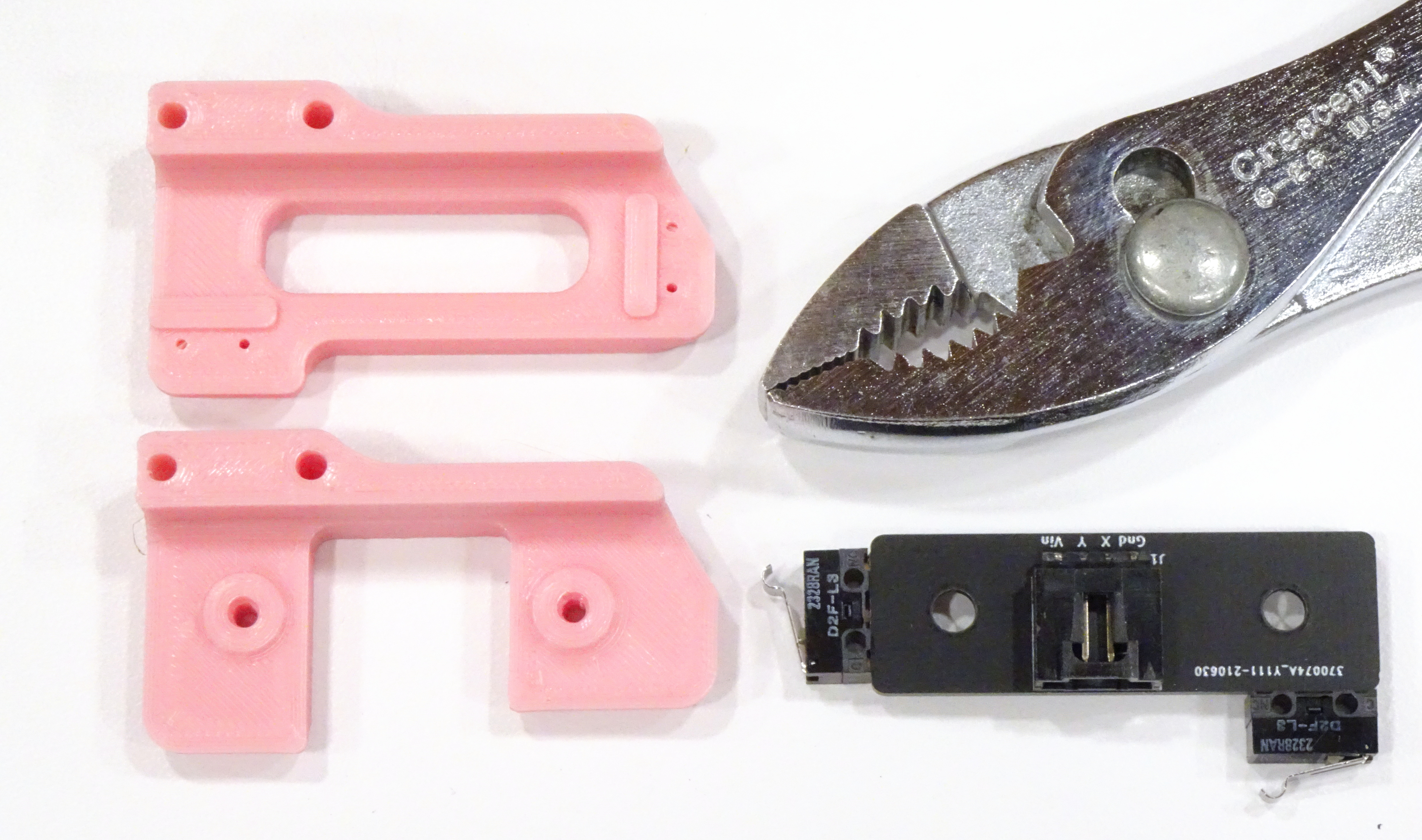
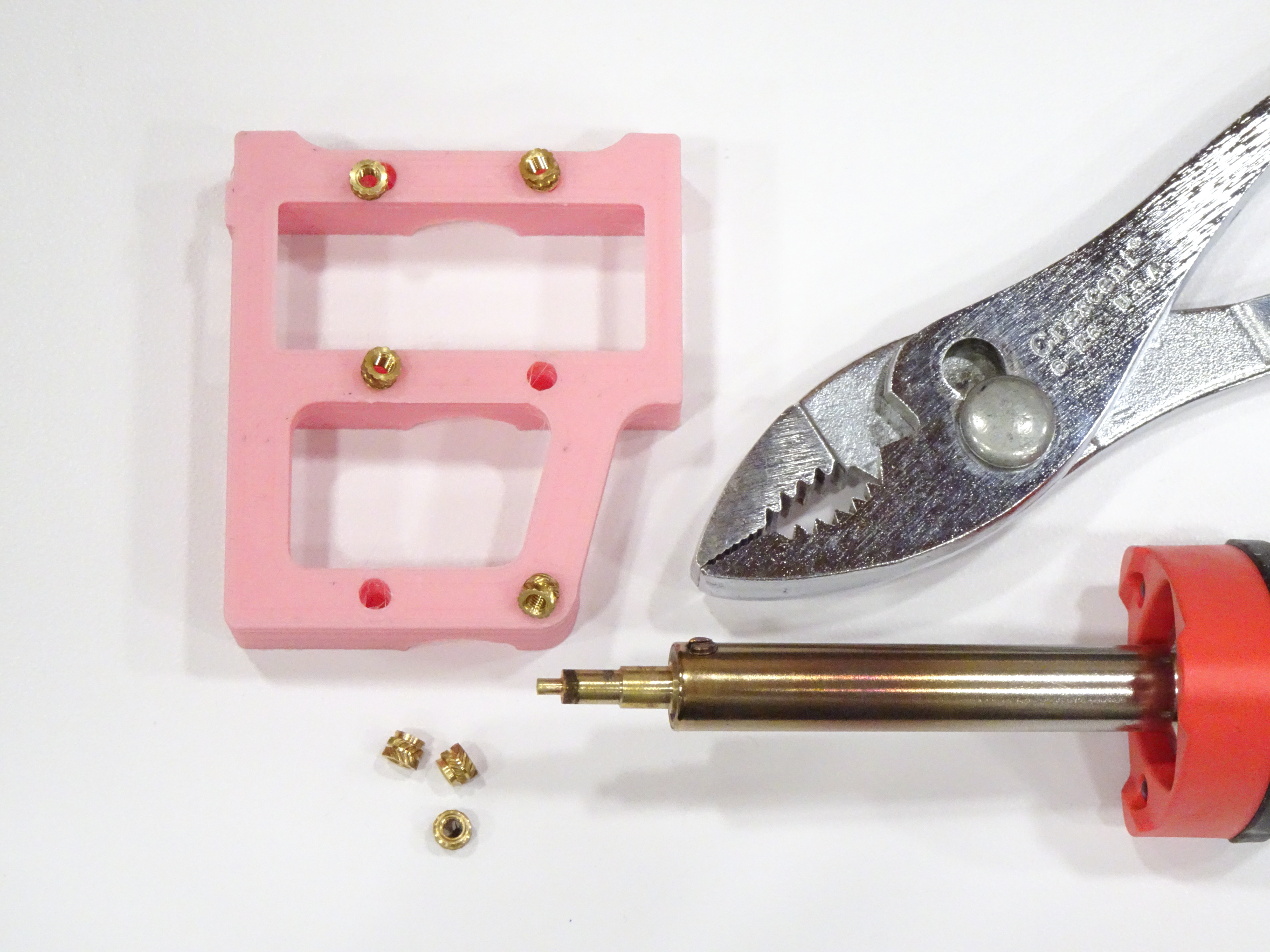
Case in point about not minding a substitution, Fysetc clearly calls out that they’ve provided an X-Y limit switch PCB accepting a single cable rather than separate limit switches requiring soldering and DIY cable; and they provided a link to a new limit switch mount to use with it (lower). I’d already printed the mount for separate limit switches (upper) before noticing this; no big deal.

Fysetc X-Y limit switch module for Voron 2.4 3D printer, component side

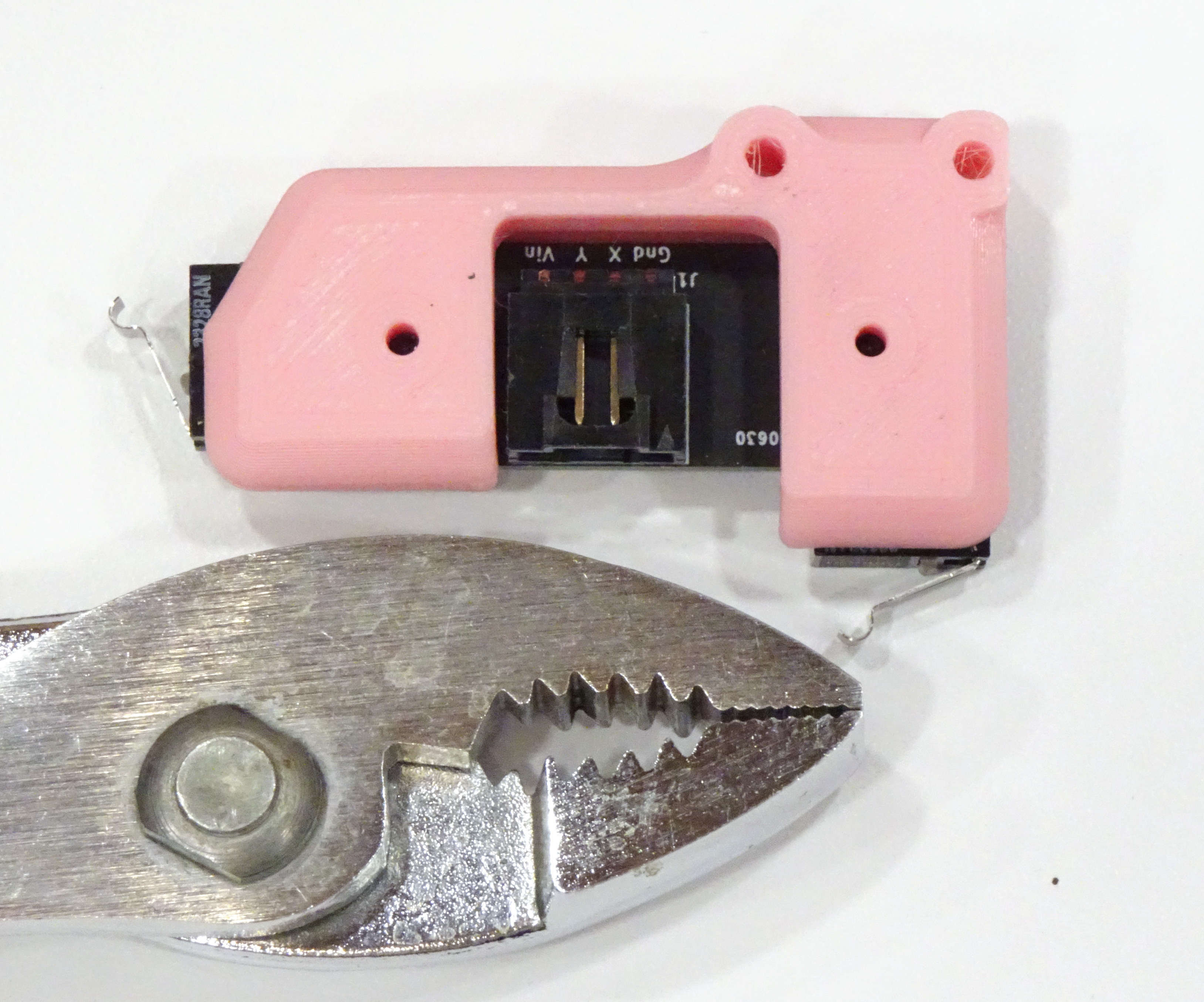
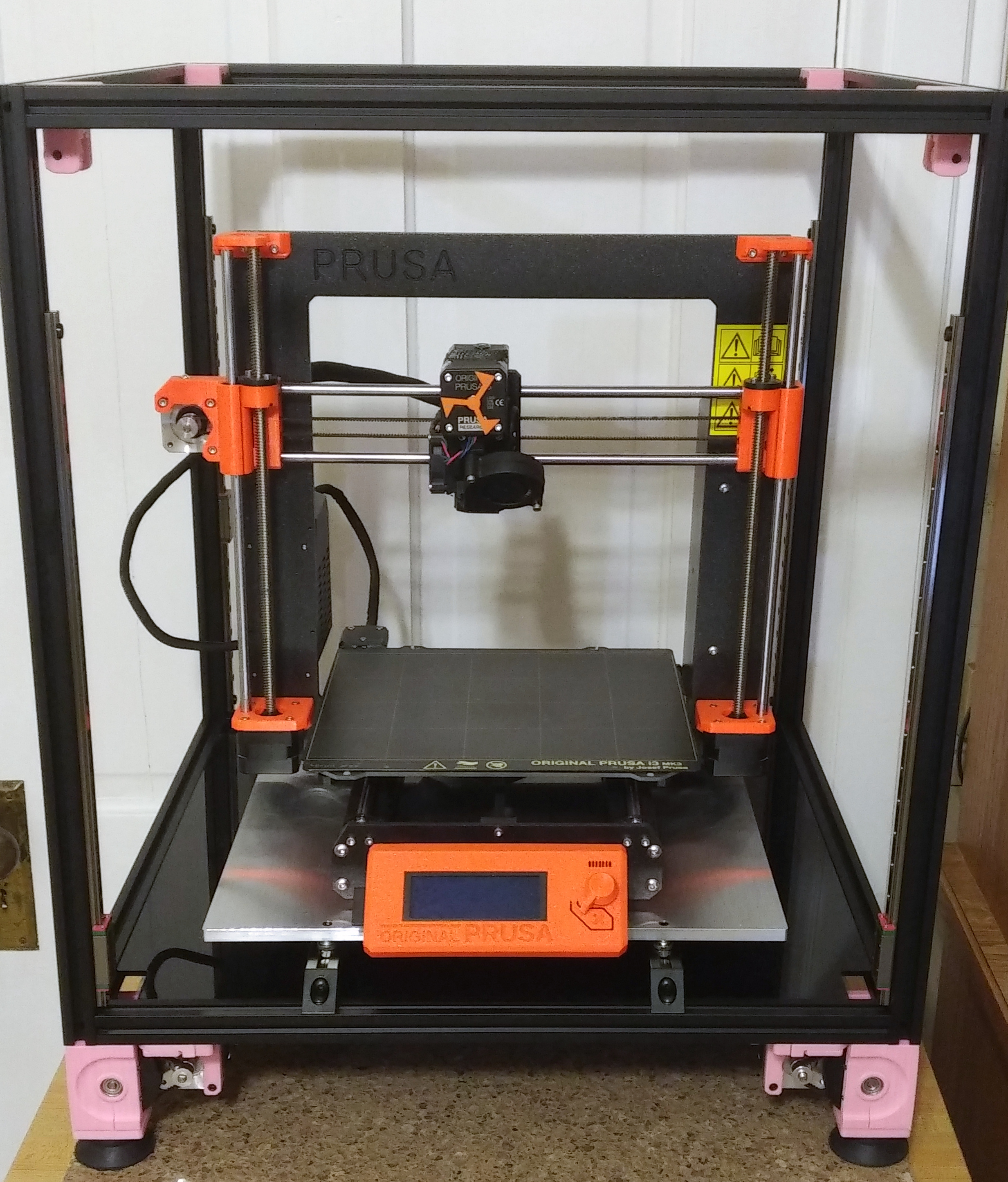
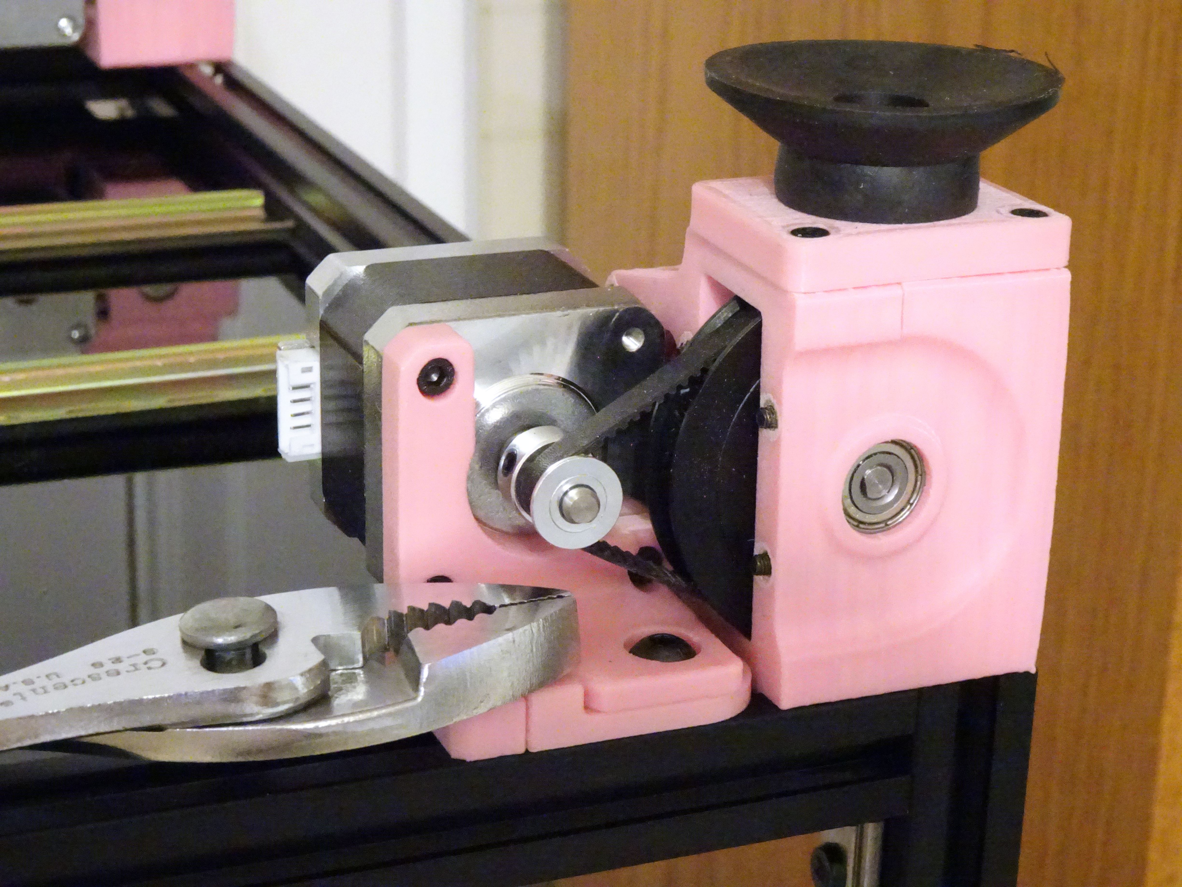
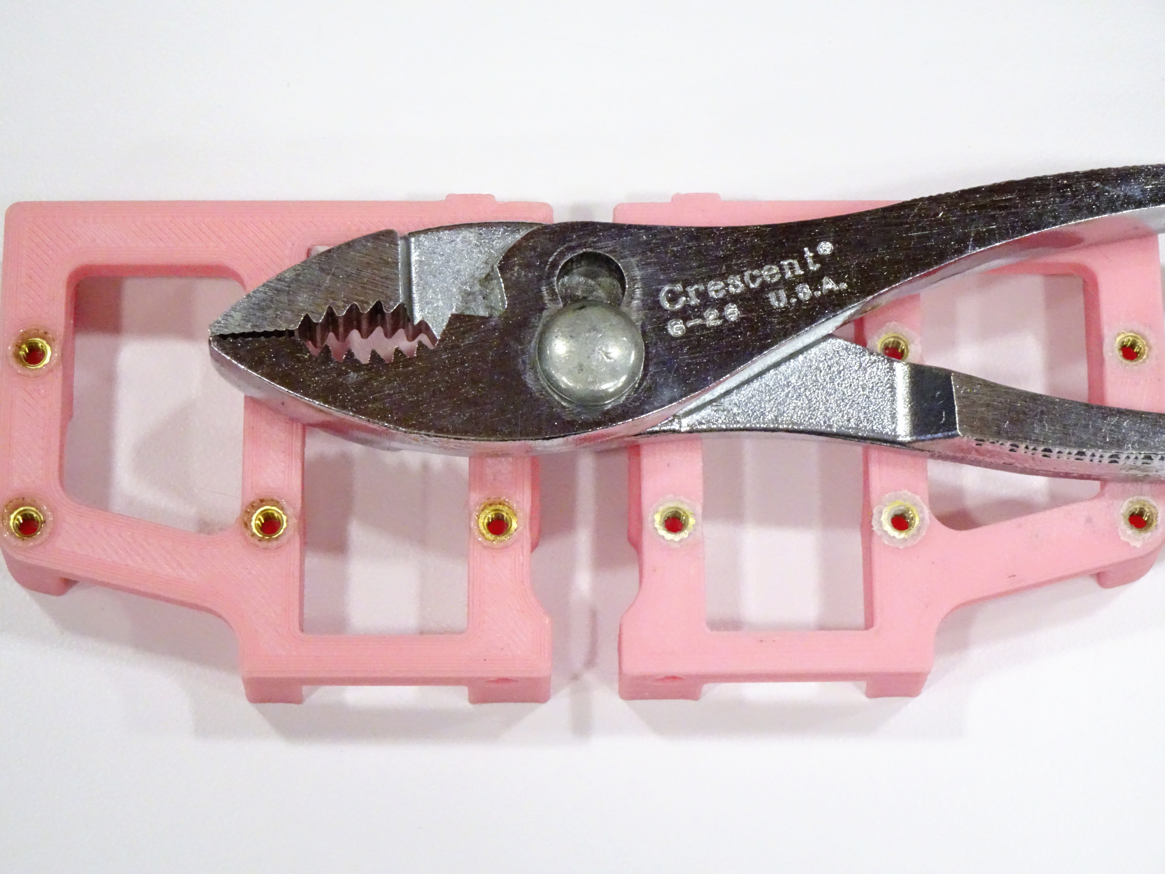
Assembled, it’s sleek and cute.

Fysetc X-Y limit switch module for Voron 2.4 3D printer, solder side

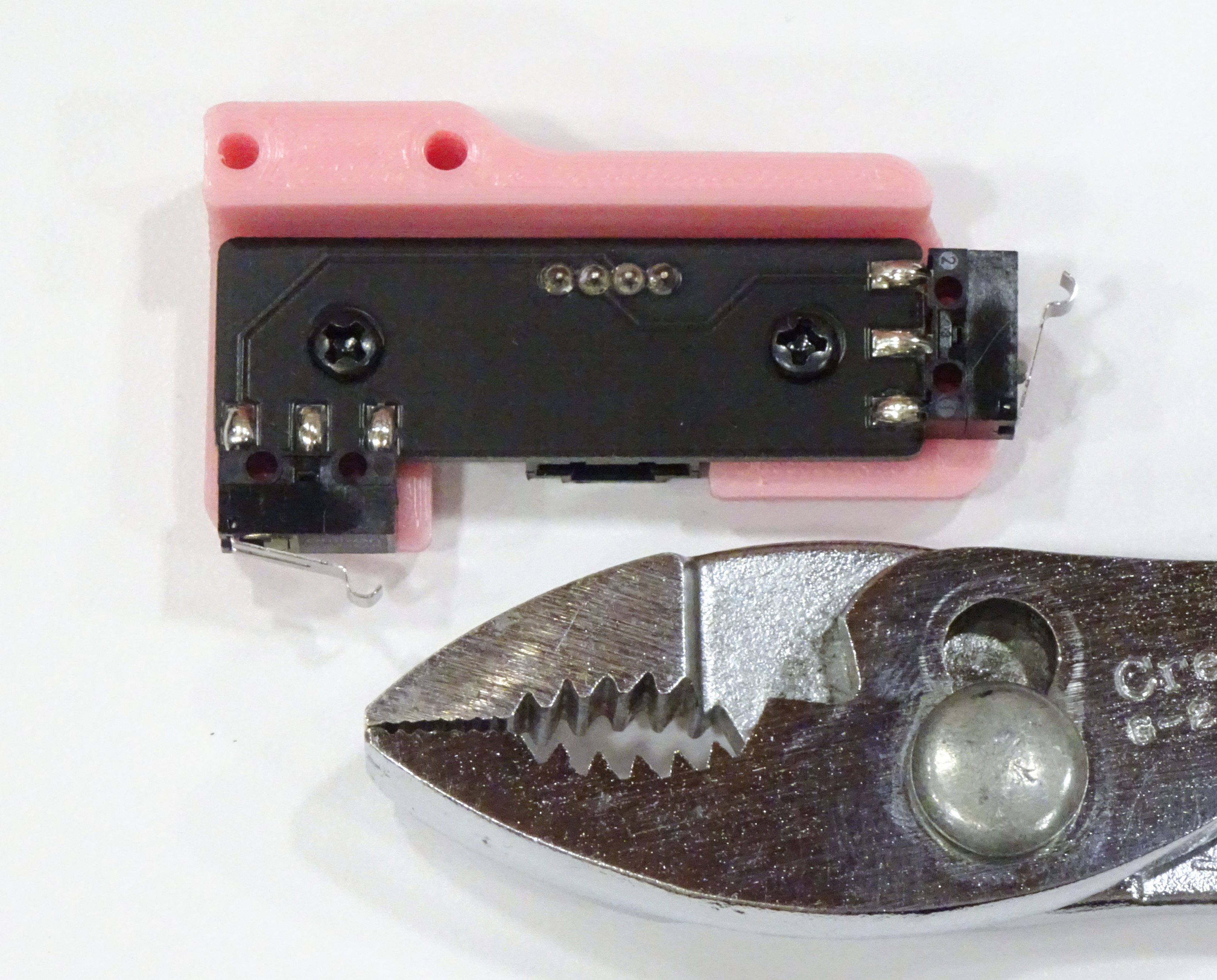
It does differ from most of the Voron assembly in that it looks to me like it’s made to be installed with flat- or oval-head screws (countersunk on the back side of the head) and there are none in the kit. I made do with M3 sheet metal screws, which are loose in the PCB holes but cinch it down fine when tightened; but for someone who doesn’t have a supply on hand, this could cause an extra trip to the hardware store.

Voron 2.4 Build — AB Blocks

Thursday, November 25th, 2021

The Voron 2.4 has a “CoreXY” drive system, meaning instead of having one axis’s stepper on a gantry moved by another axis’s stepper, it has two steppers in the back corners connecting across the Y rails and the X gantry to the printhead with a complicated routing of two belts, to reduce mass of the gantry and facilitate higher acceleration. Turning a single stepper would move the gantry diagonally; so the two steppers work together to perform Cartesian moves and are called A and B instead of X and Y.

Voron 2.4 AB blocks with idler pulleys installed

The instructions have you insert these two M5 machine screws as well as three M3 machine screws before building the A and B blocks’ idler pulley stacks; but there is no earthly reason to insert the M3 screws until after you’ve built and secured the idler stacks and you’re ready to attach the steppers, so just don’t.

Voron 2.4 AB blocks showing motor orientation

The instructions omit that the steppers need to be installed with their cable connectors in this orientation 20220601 edit — with their cable connectors facing toward the center of the back plane of the printer.

Voron 2.4 AB blocks with motor pulleys

The instructions again tell you to put the pulleys on the motors with threadlocker as the first step of assembling this stage, before assembling the blocks and installing the motors onto them. No. Again, no. It’s only a wee bit inconvenient to wait until the motors are affixed to the blocks before installing the pulleys, and it allows you to align the drive pulleys to be planar with their idlers, which seems important.

One timing pulley is installed teeth up, the other teeth down, corresponding with the position of the single idler pulley on each block.

If you want to criticize the print quality and fit of my Voron parts, you could rightly do that … or you could reflect on the fact that what I’m doing here is assembling a new, better 3D printer.

Voron 2.4 Build — Build Plate

Wednesday, November 24th, 2021

Voron 2.4 frame with built plate installed

The 350-mm-square build plate is a big boi, massing 3 kg.

Prusa MK3S inside Voron 2.4 frame

Big enough to hold a Prusa.

registering Voron 2.4 heating pad on build plate

Being a little bit … detail-oriented … I clamped guides onto the underside of the build platform to ensure good registration of the adhesive heating pad.

The Fysetc kit came with the thermistor already adhered to the underside of the heating pad. This seems not ideal for accurate temperatures and for accurate PID tuning of build plate temperature, especially with so massive a build plate. I tried prying at the thermistor’s adhesive pad and quit trying for now; but I may need to relocate the thermistor later to outside the footprint of the heating pad, to at least measure some thermal conductivity through the build plate. May even need to buy a replacement thermistor if I can’t extricate this one intact.

It’s easy to loosen the build plate screws and slide the plate back and forth on the deck rails; and I understand that (although the assembly manual doesn’t mention it) a calibration step will be positioning the Z limit switch underneath the back end of the Y travel and then scooting the build plate as far back as it can go without touching the Z switch assembly.

Accordingly, it would be a mistake to cover up the build plate screws with the Fysetc kit’s adhesive-backed fridge magnet that holds down the spring steel build sheet. Although it is true that once assembly and calibration are complete, I don’t expect to need to move the build plate again, it is also true that the spring steel sheet will still stick well to the fridge magnet with a hole in the magnet above each build plate screw. Whose positions I marked on the magnet before installing the build plate on the frame.

Finally, I’m thinking about ways to minimize heat transmission from the build plate to the deck rails. No need to heat up the rails, and particularly no need to heat up the acrylic deck plate, which I hear has a reputation for warping from the heat. It’s probably only a small improvement, but I’m planning to replace the black oxide machine screws holding the build plate to the deck rails with stainless, as I understand stainless has a lower thermal conductivity. I’m pondering searching for ceramic standoffs instead of the provided knurled knobs of unknown metal; and I’m thinking of sliding aluminum bubble wrap insulation between the deck plate and the build plate.

Voron 2.4 Build — Z Motors

Monday, November 22nd, 2021

Voron 2.4 3D printer Z motor assemblies

The Z motor mounts have been revised (shown here) since the assembly manual was prepared (not shown here).

The assembly manual shows, but doesn’t emphasize, that each motor’s cable connection needs to face as shown here relative to the mount or the cables will be unhappy later.

Voron 2.4 3D printer Z motor and pulleys installed

The assembly manual instructs you to install the pulleys on the Z motors with threadlocker on the set screws as the first step of Z stage assembly. If you do, you won’t have any reference to align the motor pulleys with the 80T pulleys and they may be nonplanar, which the belts really won’t like.

Save motor pulley installation until motor installation; leave the pulleys loose while bolting down the motors; and install threadlocker and tighten the set screws after the motors are installed and tightened to the frame. You can ensure proper pulley alignment and it works fine.

Voron 2.4 Build — DIN Rail Slots

Sunday, November 21st, 2021

Underside of Voron 2.4 printer with DIN rails

No amount of optimism will make the M5 machine screws fit into the slots in the DIN rails. The earlier one files that out, the better.

Voron 2.4 Build — Rubber Feet Have Extraneous Screws

Sunday, November 21st, 2021

3D-printed pulley mount, rubber feet, and bolts

No amount of optimism will make the giant screws that came in the rubber feet fit into the M5 nuts trapped in the Z pulley assembly. The earlier one figures that out, the better.

Voron 2.4 Build — Z Pulley Stack

Sunday, November 21st, 2021

Voron 2.4 pulley set

The first stage of assembly after the frame is the pulley set for the Z stepper in each corner of the printer (four Z motors, and belt-reduction, and belt attachment to the gantry). The instructions call for the 625 bearings and the GT2 20T pulleys … so which of these unlabeled bags would those be?

Well, I can rule out the bags with two and three parts, since this needs four. I can rule out the spool-shaped pulleys since that’s not what’s shown in the instructions. That leaves two sizes of pulleys and it must be the larger, as a nearby assembly step calls for the 18T pulleys, which one expects to be smaller than 20T pulleys. And from the published dimensions of 625 bearings, they must be the larger, whose size relative to the 20T pulley does match the assembly diagram.

Voron 2.4 Z pulley stack

The shaft is longer than the stack of pulleys, bearings, and shims, so where to position the pulleys within the stack slack? I opted for squished to center as tightly against the shims as possible; and this works out to have been a good choice, as the black 80T gear comes very close to the edge of the recess on this part and its mate, so moving it toward center and keeping it from sliding around are important.

Voron 2.4 Build — Heat-Set Inserts

Sunday, November 21st, 2021

Heat set threaded inserts for 3D-printed parts

The printed Voron parts make extensive use of threaded brass heat-set inserts. I’d installed a few before using my regular soldering iron; but with as many as I need to do on the Voron, I sprung for a cheap brass insert tip made to fit low-end Weller and Hakko soldering irons. Since I didn’t have any low-end Weller soldering irons, I also sprung for one of those.

The heat-set tip is a loose fit into the inserts so that it doesn’t drag them back out of the plastic, therefore it doesn’t at all pick up the inserts off the table. After thinking through some bad ways to get the inserts onto the heated tip, the perfectly workable approach is to set the inserts onto the workpiece, spear them in place with the iron, straighten, let them heat up, and let just the weight of my hand slowly sink them into the plastic.

3D-printed parts with heat set threaded inserts before and after sanding displaced plastic

The process does displace plastic around the pilot hole and raise it above the level of the surface. So (left) I’m being careful to sink the inserts down until they’re flush with the original surface and (right) I take a few passes on the 180-grit sandpaper to remove the resulting volcanic cone.

Voron 2.4 Build — Printed Parts

Sunday, November 21st, 2021

Like many 3D printers on the market, the Voron contains 3D-printed parts; and because it’s a design, not a product, you can print your own parts or you can buy the parts from the Voron community’s Print It Forward program. The printer requires about 1.5 kg of the primary color and 0.3 kg of the accent color! I had a couple of Ender 3 Pros running for a couple of weeks to print the parts that nearly fill a 2-gallon kitchen bag.

Voron 2.4 frame with printed parts

The instructions are very specific to use ABS rather than PLA due to expectations of enclosure temperatures up to 60°C; and although the Voron glamor shots feature black parts with red accents for a very Empire vibe, the ABS that I had on hand in bulk was pink. Bubblegum pink. That will make my printer’s look more of a Pink Five Strikes Back or Legally Blonde dates a goth.

sanding the face of a 3D-printed part

The Voron is smartly designed with parts that are easy to print and then bolt together rather than overly complex parts with challenging overhangs and bridges. Accordingly, though not specified in the instructions, where mating surfaces were the top faces of their prints, I’m giving them a few passes on 180-grit sandpaper on a flat surface to reduce roughness and get the cleanest joints I can.

Voron 2.4 Build — Z Linear Bearing Placement

Sunday, November 21st, 2021

Voron 2.4 frame with Z linear bearings installed

It’s hard to tell from the assembly manual, but the Z-axis linear bearings face toward the center of the front and rear side faces of the printer.

Don’t do like I did here and put them in the front and rear faces.

Their placement is not documented in the assembly instructions, nor clear in the assembly diagrams. It wasn’t until I installed the gantry in the frame that I found that my placement was wrong.