Archive for May, 2011

Stratasys ABS Rapid-Prototyping Machine

Monday, May 30th, 2011

Another heretofore unfinished old post, this one from January 2010:

I was over at the aviation department last week and happened upon the installation of a new Stratasys rapid-prototyping machine.

Stratasys ABS rapid-prototyping machine, front left view

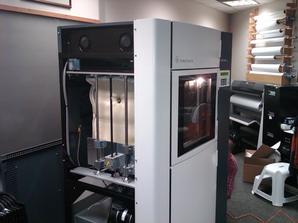
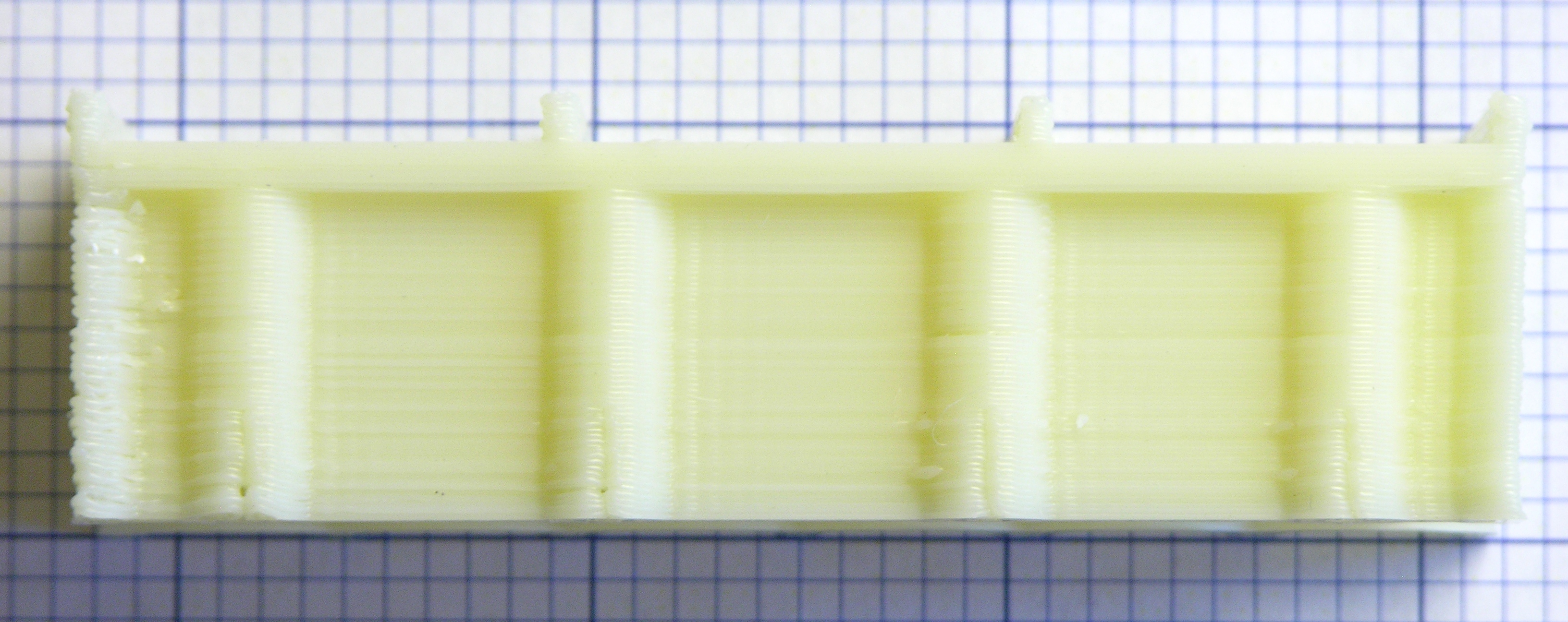
It has a much larger build chamber than NIAR’s previous ABS machine — this one is something like 14″ x 14″ x 18″.

Stratasys ABS rapid-prototyping machine, left side open

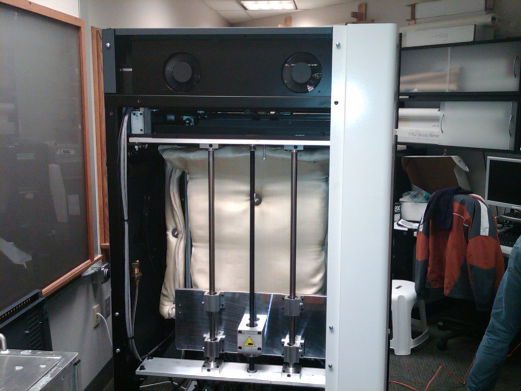
The case was open and I was intrigued by the thick blanket of insulation around the build chamber. I asked the installer if the whole chamber was heated and he said yes, to 80°C. Interesting point of reference, as RepRap / CupCake owners seem to have settled on 60°C as the standard temperature for heated build platforms.

Stratasys ABS rapid-prototyping machine, hazy shot of extrusion head

It was fairly dark inside the build chamber and I couldn’t get a great shot with my cell phone camera, but you can see the extrusion head with two nozzles for support and build material. I found it interesting how extremely broad and shallow the white nozzle cones are — maybe it helps prevent snags?

Filament from Stratasys rapid-prototyping machine

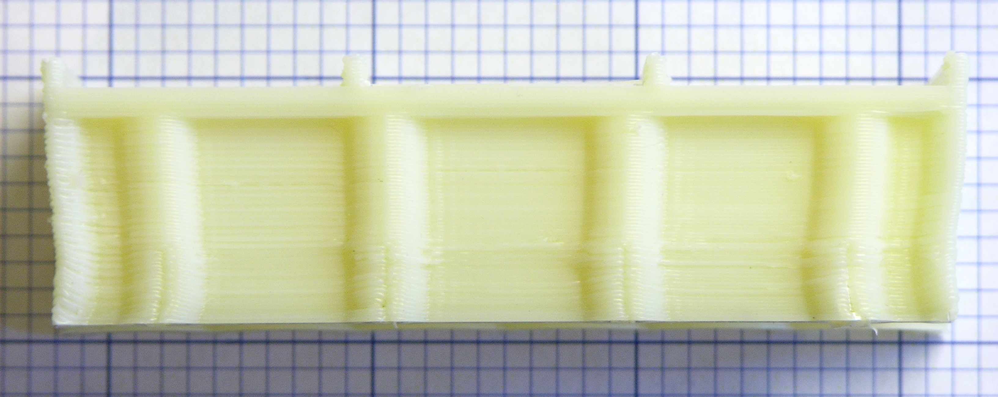
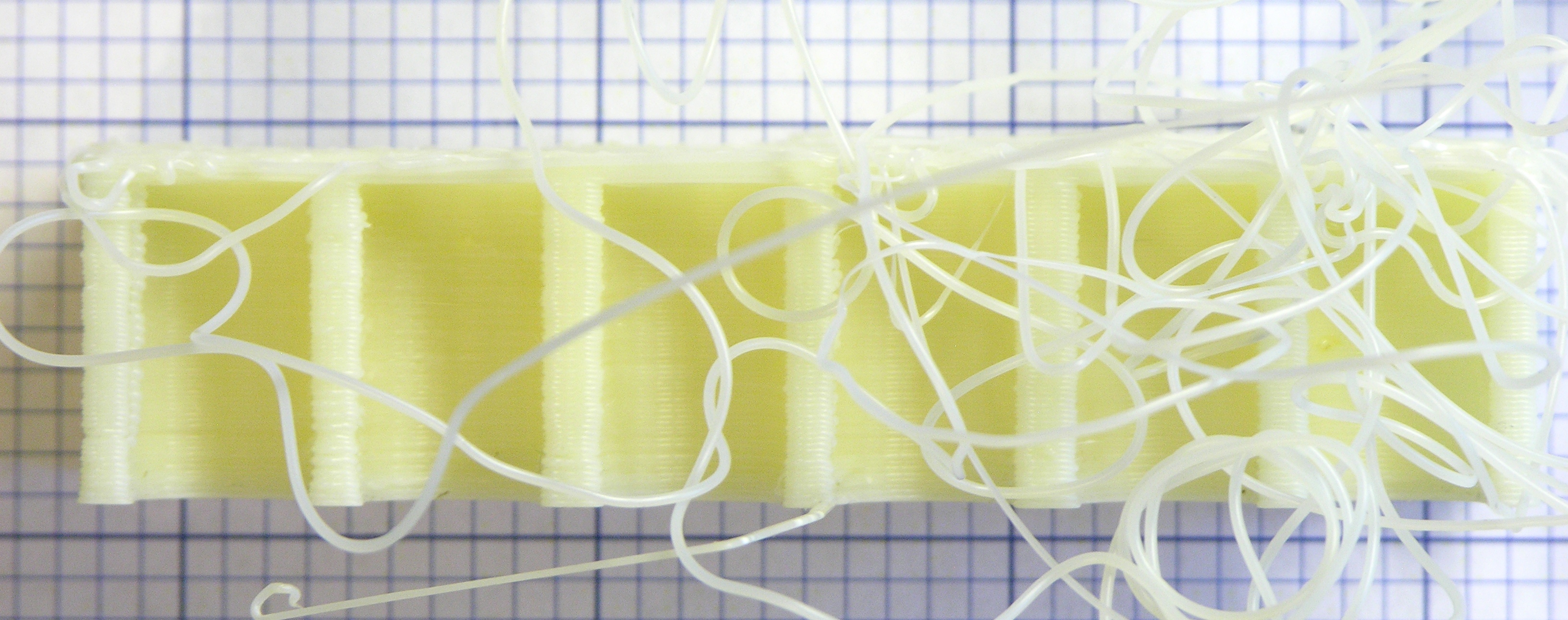
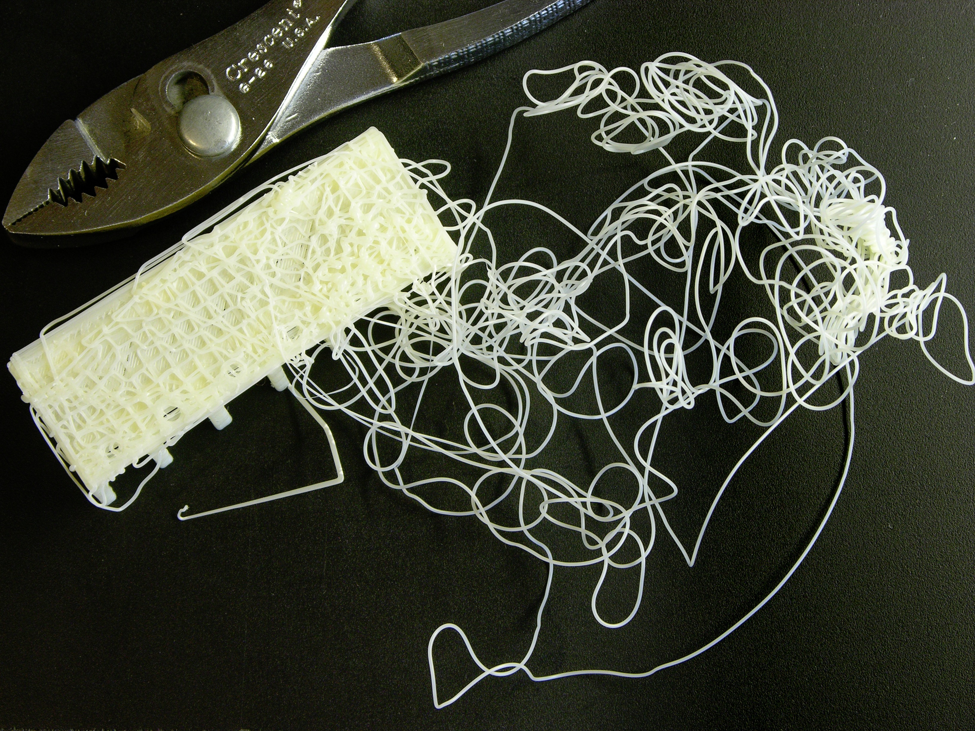
With the lab manager’s blessing, I fished two filament strands out of the trash. The upper, black filament is ABS; the lower, translucent brown filament is a dissolvable support material that apparently washes out in an agitated hot water and detergent bath. Wish I knew exactly what it was!

I measure the diameter at .070″ ± .001″ ≈ 1.778mm ≈ 1.75mm ≈ .069″, so it looks like they’re using 1.75mm filament. The stretched section on the end is recognizable as having been in the hot end and then backed out.

Note the toothmarks all the length of each filament (about 3m), suggesting that either something is pushing the filament from that far back or (more likely) the hot end has a quick-release for cleaning and this filament was run through the machine after removing the hot end.

PLA + Ignorance = Broken Extruder

Sunday, May 29th, 2011

I got a roll of PLA to try making some clear objects on the CupCake. I had read on the MakerBot wiki about the techniques for and challenges of printing PLA but still had trouble feeding PLA into the Plastruder MK3 and chasing out the ABS that I’d been using.

MakerBot CupCake Plastruder MK4 with stripped PTFE barrier

When feeding in the PLA, ABS came out for a while and then things stopped. Something happened inside the PTFE (Teflon) thermal barrier and the brass heater barrel was pushed out the bottom.

Later kits have a nut between the PTFE barrier and the metal washer so the long black bolts pulling on the washer in turn pull on the nut which has a stronger grip on the threads than the PTFE, dramatically reducing the risk of the brass barrel slipping out of the PTFE barrier and dramatically increasing the risk of cracking the acrylic retainer at the top. It’s recommended to replace it with a metal retainer.

PLA clogged on MakerBot CupCake Plastruder MK3 nozzle assembly

Today I had time to disassemble the Plastruder and unthread the heater barrel from the PTFE barrier. Looks like the PLA melted, the PTFE got warm and softened, the PLA oozed around the heater barrel, and then the PLA solidified and the barrel was pushed out the end of the softened PTFE.

I chipped the hardened PLA off the end, then searched for a solvent that would dissolve the PLA out of the barrel. I was surprised to find no information online (I do not assert that there isn’t any but merely that I didn’t find it) and tried acetone. During the time I waited, it didn’t dissolve the PLA completely, but it did soften it enough to scrape it out of the threads with a wire brush and goop it out of the barrel with a drill bit.

Scorched nichrome heater wire on MakerBot CupCake Plastruder MK3 nozzle

Since something in the thermal insulation had been previously damaged by deliberate immersion in water, I ended up deciding to peel apart the whole heater assembly. I suspect the water-soaked kapton tape adhesive closest to the nichrome heater is what scorched and I still have faith in the magical powers of kapton. I just know its weakness now.

On the bright side, I get to rebuild my heater from scratch and make it beautiful again.

On the dim side, I need to replace the PTFE barrier, which is swollen beyond even making contact with the brass threads, and the ceramic insulation that wrapped the heater, which was no longer pristine. I see that the MakerBot store has them in stock and affordable, and I reckon I’ll order them this week unless I hear a brilliant alternative first. The nichrome wire’s fiberglass insulation looks and feels intact — I think it’s saturated with scorch from the kapton rather than being damaged itself — but I’ll probably order more of it too.

Anyone successfully using PLA, I’d love to hear what temperature works well for you and what technique you use for changing from ABS to PLA.

Solar Charging and Switching Circuit for Outdoor Sculpture Installation

Sunday, May 29th, 2011

Over the winter, my friend Steve Atwood got a commission for a sculpture to be installed in the Wichita Falls, TX Kemp Center for the Arts “Art on the Green” sculpture garden from May 2011 – 2012.

Lure 22 V2.0 by Stephen Atwood at Kemp Center for the Arts, Wichita Falls, TX

He had in mind to continue a series of his sculptures based on the form of a fishing lure but wanted to enhance this sculpture with one or more LEDs, preferably that would come on only at night. We discussed a wide variety of options that we hope to develop for another installation in the future; but in the end, in the interest of time for this project, Steve found control modules that flash up to five LEDs at random and installed them behind a set of cones protruding from a recessed panel.

He asked how to make the LEDs turn on at night and also wondered whether he could power them for a year from a primary battery or whether he should use rechargeables.

Lure 22 V2.0 by Stephen Atwood at Kemp Center for the Arts, Wichita Falls, TX

About seven years ago, I had come into possession of some discarded solar yard lights, and out of curiosity had reverse-engineered their charging and control circuits. Since yard lights accomplish both functions — charging and switching — I figured the circuit would be perfect for the sculpture. I was able to find one and instruct Steve how to modify it for his needs.

Solar yard light schematic

The circuit is very simple and I find it rather elegant. During the day, the solar panel assembly (left — for want of a proper schematic symbol, I just drew another battery) charges two AA cells through a diode that prevents the battery from damaging the panel with reverse voltage at night. Additionally, through the R1 – R2 voltage divider, the solar panel pulls up the base of Q1, switching it off and allowing R3 to pull up the base of Q2, switching it off and switching off the load LED1.

At night, the panel’s output approaches 0V and R2 pulls down Q1‘s base, causing Q1 to conduct and pull down Q2‘s base (in a Darlington-like arrangement — I don’t know whether it’s still considered a proper Darlington with R3 pulling up the Q1 emitter – Q2 base connection), switching on Q2 and LED1. In fact, depending on the panel’s exact voltage, the load may switch on even before full darkness, and R1 – R2 can be tweaked to tune the turn-on point.

Control board from solar yard light, modified

Steve removed the LED from the control board and replaced it and the fly wires for the solar panel and battery with screw-terminal connectors for ease of installation inside the sculpture. He bought a new solar panel with a higher output voltage to charge the higher-voltage battery for the white LEDs he wanted to use (the yellow LEDs in my yard lights didn’t require as high a forward voltage) and milled a Lexan cover for it to protect the panel from hail, with an O-ring groove to protect it from rain as well.

With higher battery and solar panel voltages, Steve indicated the load was turning on before the ambient light got as dark as he wanted, so I told him how to locate R1 and replace it with fly wires to a 100K pot. After the swap, he said he was able to tune it perfectly and he was delighted.

Lure 22 V2.0 by Stephen Atwood at Kemp Center for the Arts, Wichita Falls, TX, night view

I’ve not had a chance to visit the sculpture garden and probably won’t while Lure 22 is installed. If anyone’s in the area, I’d love to hear from you how well it’s working and how well the electronics hold up over the course of a year outdoors.

Liebert Battery

Saturday, May 28th, 2011

Just found this unpublished draft from October. I had received a GXTV2-48V battery expansion cabinet for my Liebert GXT2-2000RT120 UPS and wanted to see what was inside.

Liebert GX2-48VBATT battery cabinet interior

Eight sealed lead-acid batteries are bolted down and connected through a circuit breaker / switch to the two input/output jacks in parallel.

Liebert GXT2-CABLE48V1 UPS battery cable

The cable to daisy-chain the battery expansion cabinets to the UPS is … substantial.

installed

Installed in the basement server rack (bottom) and connected to the UPS. Sure wish I had a bezel for the battery cage.

Modifying a Car USB Adapter to (Finally) Charge My Cell Phone

Saturday, May 28th, 2011

A couple of years ago, I received this automotive USB-connector power adapter as a promotion at a conference. I use it to keep my iPod nano charged in the car, but I’ve noticed it doesn’t charge my Blackberry well. To be precise, it doesn’t charge my Blackberry. In fact, I’ve never been clear whether it even slows the rate of discharge, and sometimes it seems like it speeds it. The Blackberry shows the lightning bolt charging symbol (The charging symbol is a lightning bolt, srsly? Ben Franklin is personally charging my phone?) but nobody’s home.

Note that I don’t blame the vendor whose logo happens to be on it — I’m sure they didn’t manufacture it.

Automotive USB power adapter

After driving two and a half hours a week ago starting with a half charge on my BlackBerry, plugging it in midway through the trip, and arriving to have the BlackBerry finally shut off its radio due to depleted charge; and due to being in the presence of Cort; I decided it was time to see why the adapter couldn’t provide enough charge for the BlackBerry.

Inside the Power Adapter

Sample step-down circuit using RT34063APS DC-DC converter

(more…)

CupCake Wants the Build Platform Temperature Turned Down After the First Layer

Monday, May 9th, 2011

I had previously noted the shrinking of the first few layers of a build on my CupCake and attributed it to the ABS shrinking too rapidly after extrusion because the room and the build chamber weren’t terribly warm. Although I’d leaned things against all of the CupCake’s windows so the heated build platform warmed the whole chamber, I thought that too much heat was leaking out when I prepped the print and removed the pre-print test extrusion and that it took a number of layers to heat the interior back up to non-shrinking temperature.

Large Kelly forceps with locking mechanism removed

I figured I could retain more heat inside if I didn’t have to move the front “curtain” to remove the test extrusion, so I went to The Yard and picked up a big pair of Kelly forceps. Since I wanted to use them as giant tweezers, I Dremeled off the locking mechanism, leaving myself with a big pair of plain ol’ forceps.

Mounting bracket built on MakerBot CupCake with lower layers warped

I heated the build platform and the now-more-enclosed chamber for half an hour (longer than the time it takes to print past the warped area), then sneaked the forceps in and snaked out the test extrusion. Whaddya know — the build warped in just the same way as before.

Hm.

I don’t yet have my build platform’s thermistor connected, so I’ve been running the heater open-loop using a lab power supply to adjust the temperature via current regulation. I remembered a while back when I had it so hot that the bottom half inch of my objects stayed melty-squishy while being built … and although I no longer run it that hot, I’ve been sloppy lately about turning down the current once the first layer is adhered to the platform.

Mounting bracket built on MakerBot CupCake that popped loose during printing

Maybe, I thinks, maybe the first few layers are too warm and pliable and get compressed as the layers above them cool and shrink. I uncover all the CupCake’s windows, start a print, and dial the heated platform current down from 2.7A to 1.8A after the first layer sticks down. I get perfectly straight walls, so I’m finally on the right track and it’s less heat that I need, not more

Mounting bracket built on MakerBot CupCake that popped loose during printing

but whatever temperature 1.8A delivers isn’t enough to keep the object stuck to the kaptan tape and the bracket I’m building pops loose when it’s almost finished, naturally when I’m in another room, and the last half mile of extrusion doesn’t adhere particularly well to the bracket when the bracket is no longer on the platform.

Mounting bracket built on MakerBot CupCake with minimal warp

2.7A for first-layer adhesion, 2.2A after first layer, slight shrinkage, no popping loose from the platform. Now to the point of tweaking for diminishing returns. I should maybe add a fan pointed at the platform like other folks have done, although that has its own dangers (easy to cool the platform too much).

I’m eager to get the thermistor wired up (heater PCB v1.1 will have less restrictive connector spacing); translate these currents into temperatures; and connect the heater and thermistor to the CupCake for closed-loop, PID control. I will not abide the clickety-clack of relays, so I’ll find some big FETs.