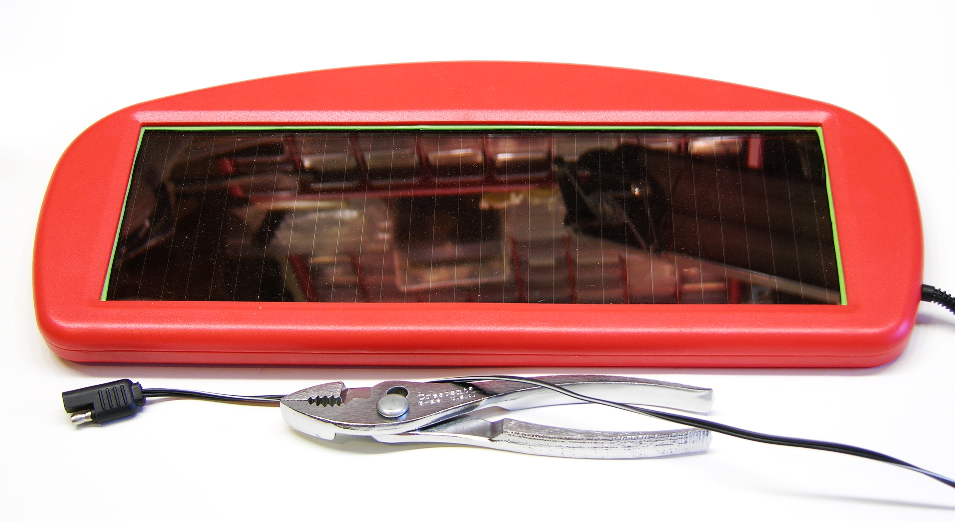
My dashboard solar charger is one of the more useful things I’ve bought from Harbor Freight. My van has some weak short-circuit and slowly drains the battery, and as I don’t use the van all that often, I was at risk of coming out to a completely drained battery. I now keep one of these on the dash and the battery is always topped off. When I first connected it, the van was sitting in shade and the (old) automotive battery measured 5V (!); after a week it was up to 9V and after another week it was fully charged. Now I don’t ever have to think about a drained battery again. At about $20 list and $15 on sale, it’s a steal.
The bus conversion project is languishing but not forgotten, and I’ve been wanting to put one of these chargers into the bus for the same reasons as I had for the van. The wiring situation is a little different, though — the bus has no cigarette lighter / power port, I’m intending to wire 12VDC throughout the bus with Anderson power pole connectors, and I might like to have multiple solar trickle chargers (even before I install larger solar panels on the roof).
The issue with multiple panels, and even with a single panel connected to a battery that will also be charged by the alternator, and even with a single panel that may still be connected to the battery at night, is that photovoltaic cells don’t like to have reverse voltage applied. The photovoltaic effect happens in a semiconductor junction, and although I can no longer find the reference I was reading the other day, I still know the cell doesn’t do well with a reverse voltage and should really be diode-protected.
Because I wasn’t sure how much (if any) circuitry was in the panel and how much (if any) was in the automotive power plug connector, I had to take both apart to (A) make sure the panel would be diode-protected even after I chopped off the power plug and (B) see whether either held any relevant / useful circuitry.
While trying to print a replacement cap for a spray bottle (which I ultimately want to do in PLA, but that’s what broke my extruder and I’m working my way back up to it), sizing the cap properly for the bottle was complicated by the cap shrinking unevenly while the build was still in progress. I knew I needed to turn down the build platform temperature as soon as the first layer had adhered; but the cap was so thin that the platform didn’t lose heat fast enough to make much difference.
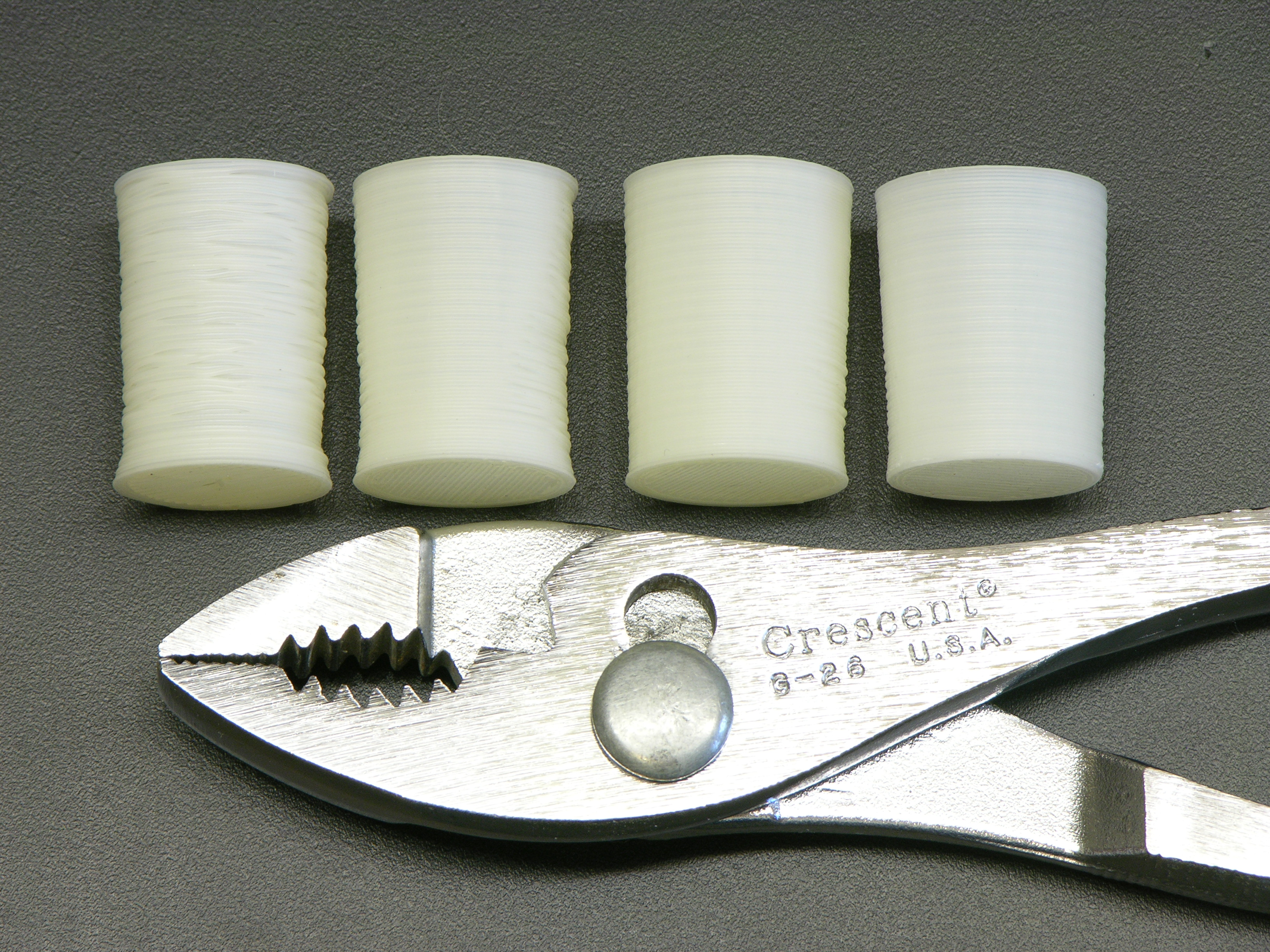
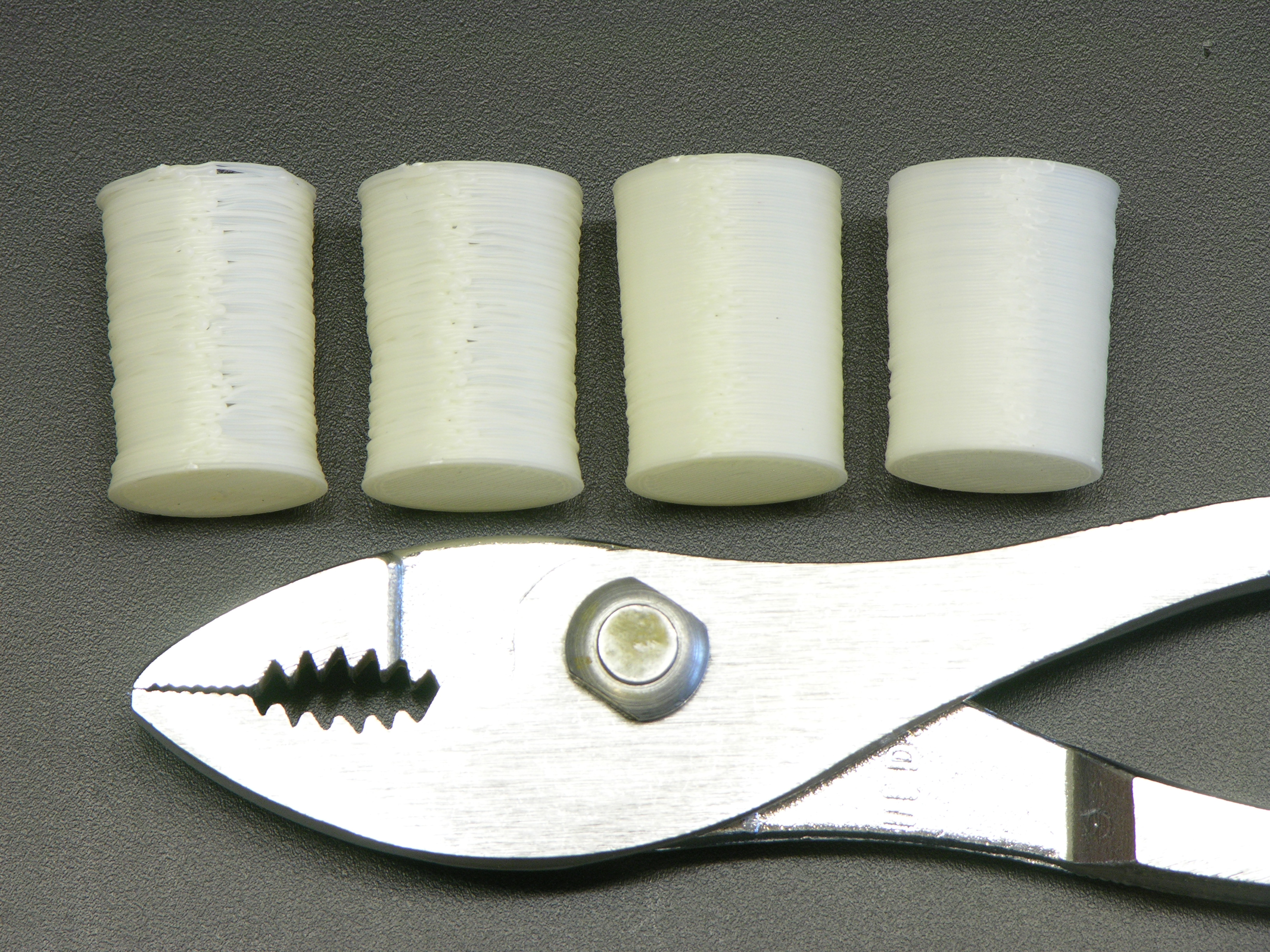
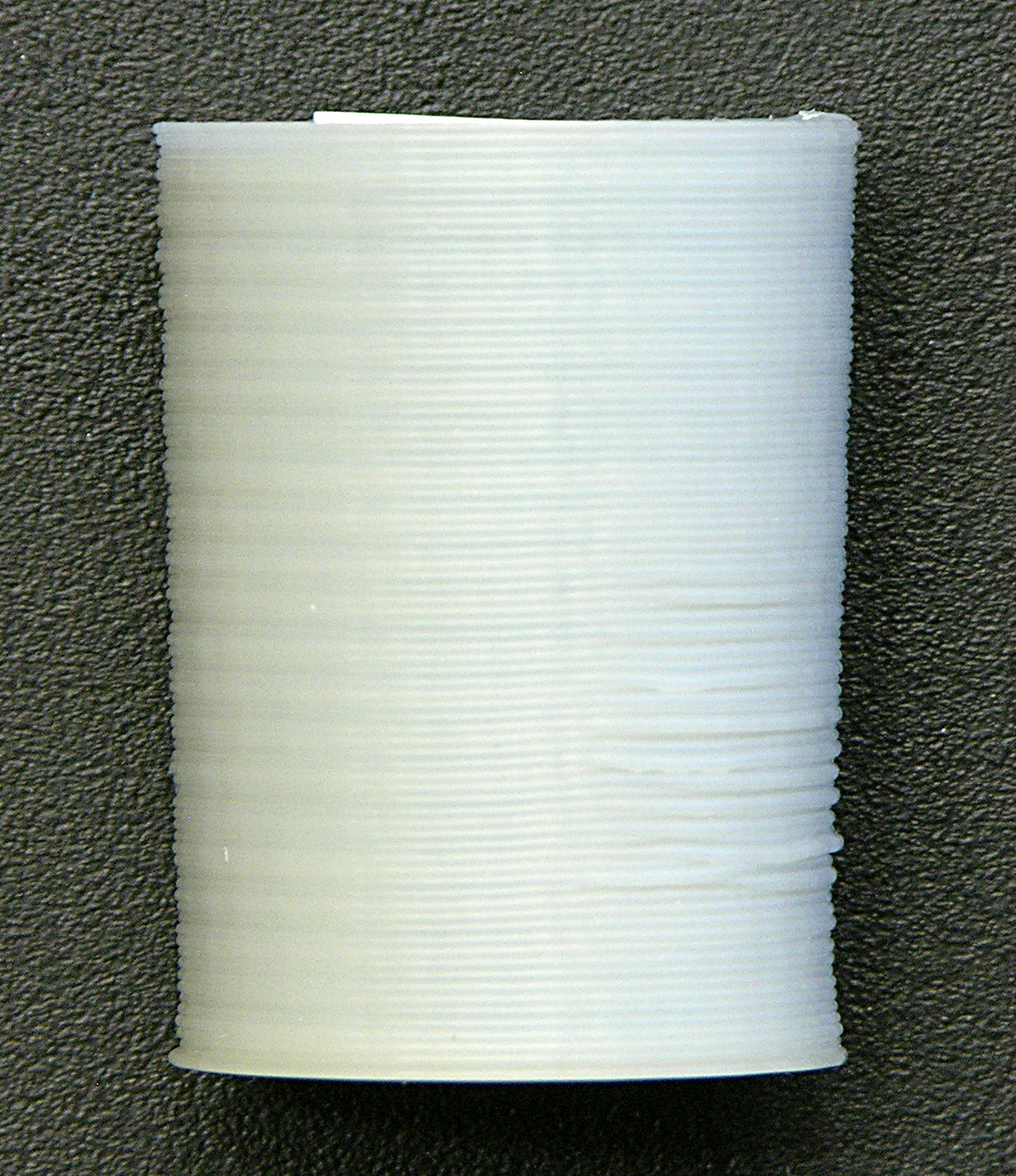
I connected a spare DC fan to my bench power supply, set it just outside the CupCake’s build chamber, and dialed it down until it barely spun. Holy schmoly! The left cap (you’ll need to click the image for the larger version), made with no cooling, looks like an art project woven out of twigs; the next one is extremely smooth on the side that was facing the fan — better than anything I’ve printed before!
The “seam” was on the side away from the fan and doesn’t look so as great as the fan side — but if one fan is good, two are surely better, right?
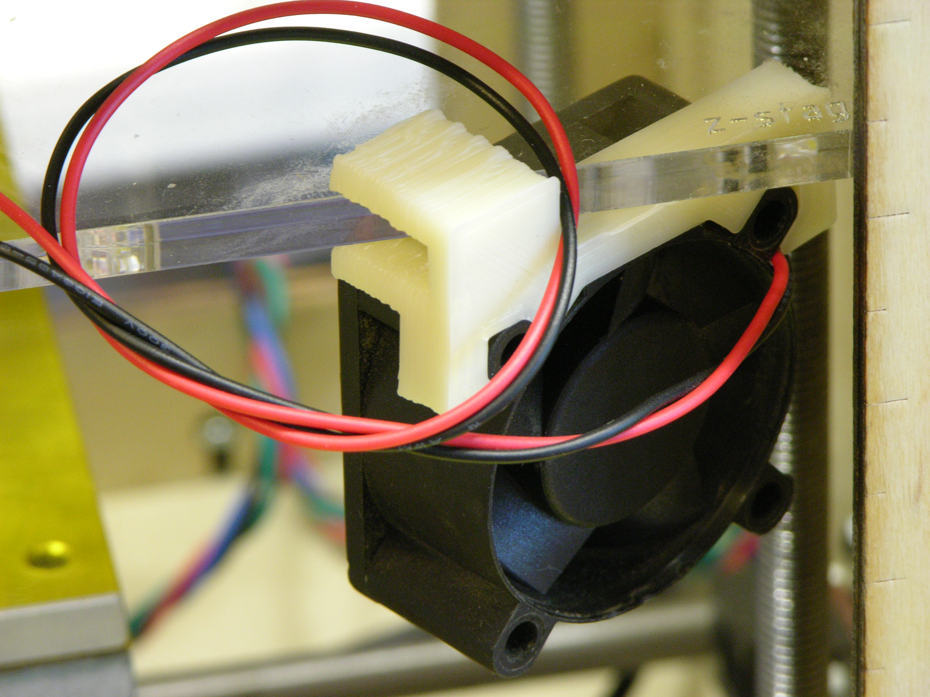
I designed and printed clips to press-fit onto a couple of 1.6″ DC fans I had sitting around (the clip is good enough to use but I have some dimensional tweaking to do before posting on Thingiverse) and positioned them at opposite corners of the build chamber, blowing around opposite sides of the object on the build platform. (Hey, I’m from Kansas. Vortices come naturally to us. Go buy a Vornado.)
The third and fourth prints above are with two fans running, trying to find optimal airspeed to cool the deposited filament but not cool the nozzle so much that the ABS solidifies before exiting. (I filed down the seam on the fourth; it didn’t really print quite that well.) I think the ultimate combination may be an enclosed build chamber to raise the overall temperature and fans to cool the layer just printed.
Many CupCake, RepRap, and Hydraraptor operators have added cooling fans, but I don’t recall seeing dramatic before-and-after pictures. Based on what I’ve observed during mesmerizing hours of watching the CupCake print, it’s obvious why it helps — without active cooling, the previous layer is still molten enough that the soft extrusion being deposited by the nozzle still applies enough force to squish the previous layer out of the way in some random direction. It may have been deposited in the right place, but it’s not in the right place any more after the next layer moves it. With cooling, it stays put.
Z-Axis Wobble and Ooze
The CupCake carries the extruder up and down on a platform supported by four threaded rods. It’s a very economical design, but the rods are less precisely straight than Acme threaded rod and aren’t a perfect fit for the ID of the pulleys at the top. The combination of these factors results in the extruder platform swaying from side to side as it moves up and down. The effect is very visible during high-speed movement but still present during low-speed movement.
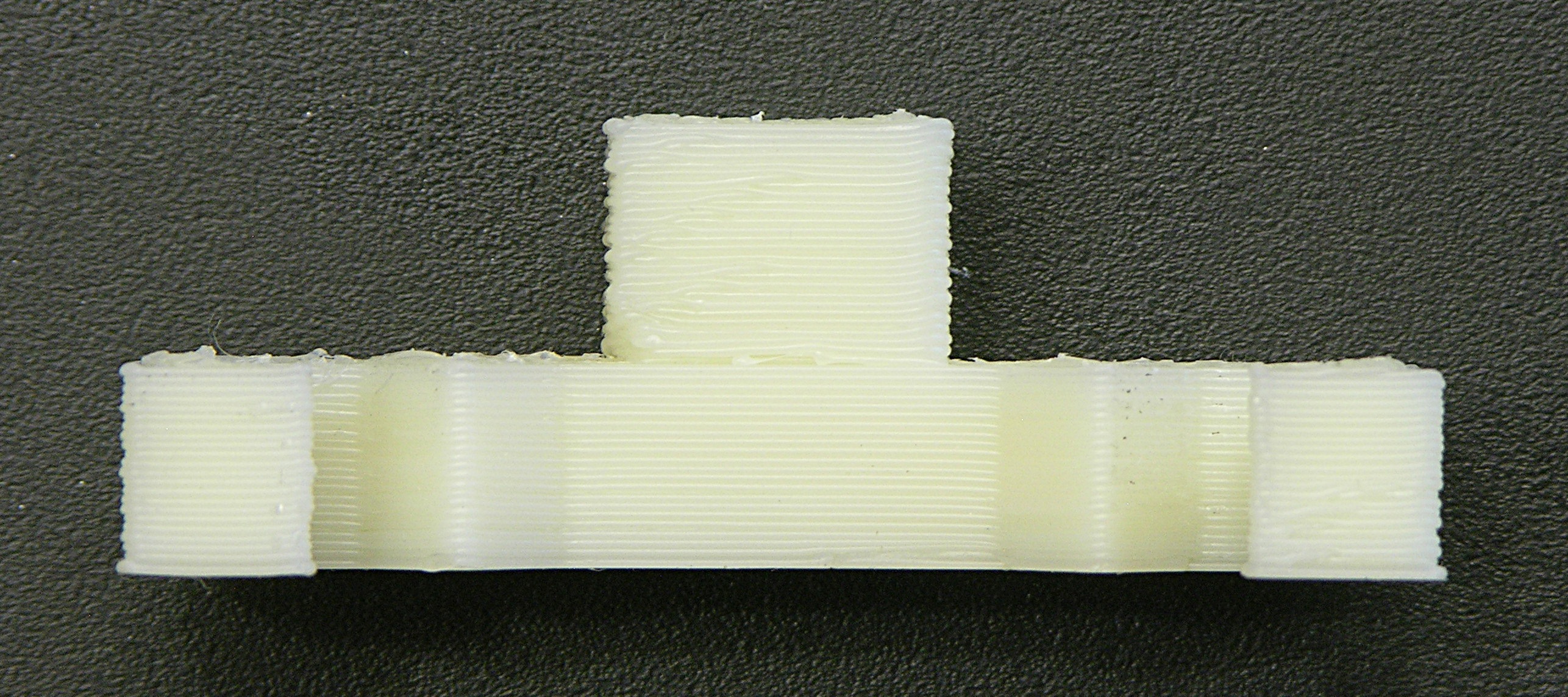
My printed objects are finally at a high-enough quality that I can see the Z-axis wobble represented in the perimeter of the object. The faint ripples visible toward the left edge — about four and a half filaments high — match the thread pitch of the threaded Z-axis rods and are caused by the extruder circling through the X-Y plane as it raises during the print.
This effect is well-known and is a solved problem. Thingiverse user “twotimes” has designed a wobble arrestor that adds rigid, smooth rods to the Z axis and new bushings attached to the extruder stage to follow them in a perfect vertical motion. It’s time!
The ripple is visible at the left end of the elevation view of this fan clip (and more obvious in person than in the photograph), but it is other imperfections that catch my eye. From the front, the bottom section looks very good, but the tower at the top (which once installed is the lower part of the extruder stage clip) has considerably more variation in filament position.
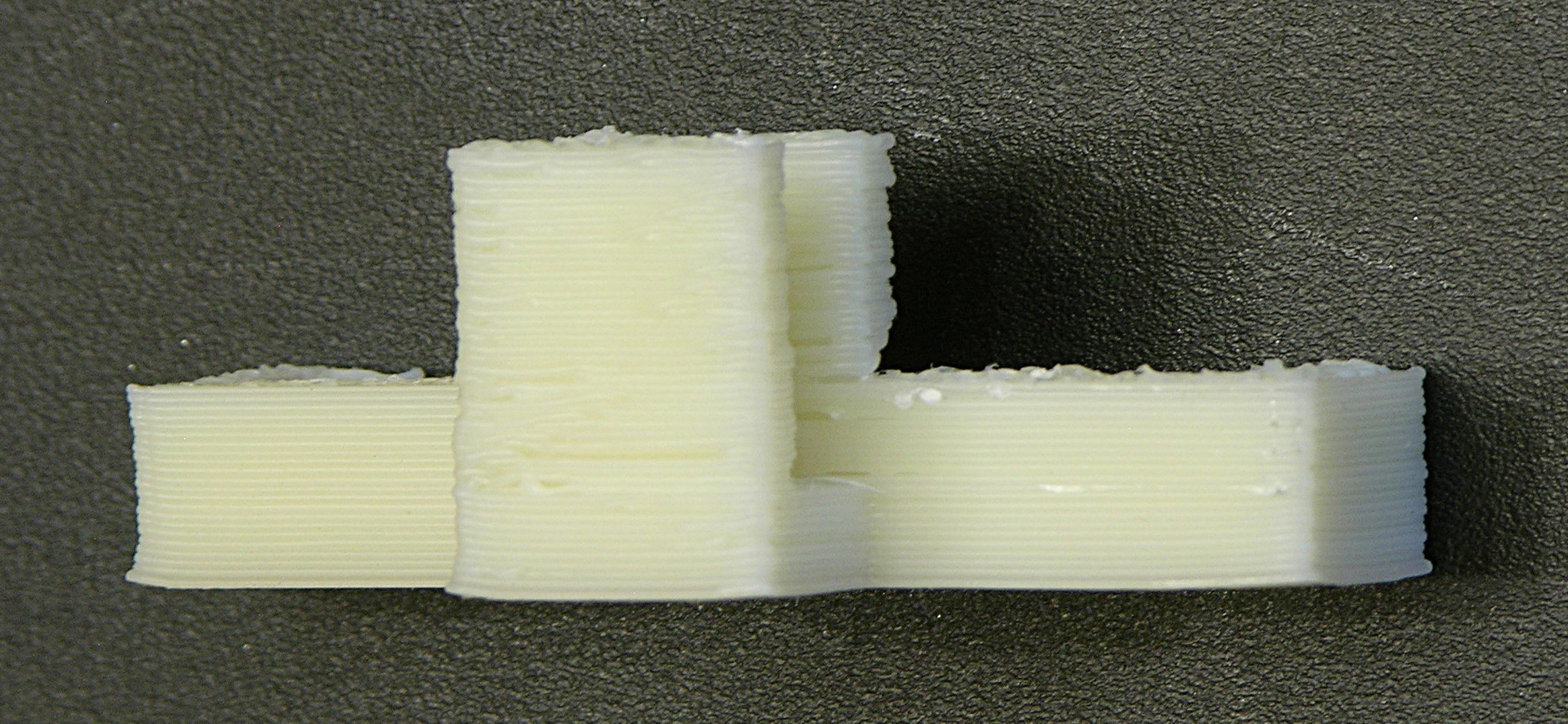
From the back, note the relatively high quality up to the top of the rearward extension for the clip — until which point the entire object has a single, contiguous perimeter. Above that level, the quality of the rear tower is much worse and the wall facing it is somewhat worse than below. The quality of the forward tower drops precipitously after the top of the main clip body.
Some of this may be due to the smaller cross-section leaving less time for the fan to cool the filament, but I place most of the responsibility on the filament drive in my extruder. It’s still the DC gearmotor design; the geartrain has a lot of backlash; and it’s not good at fast reversals. I’m optimistic that a stepper design will control the oozing, already improving the print quality, as well as making it practical to enable Skeinforge’s Cool plugin to pause printing between layers while the fan cools the just-extruded filament.
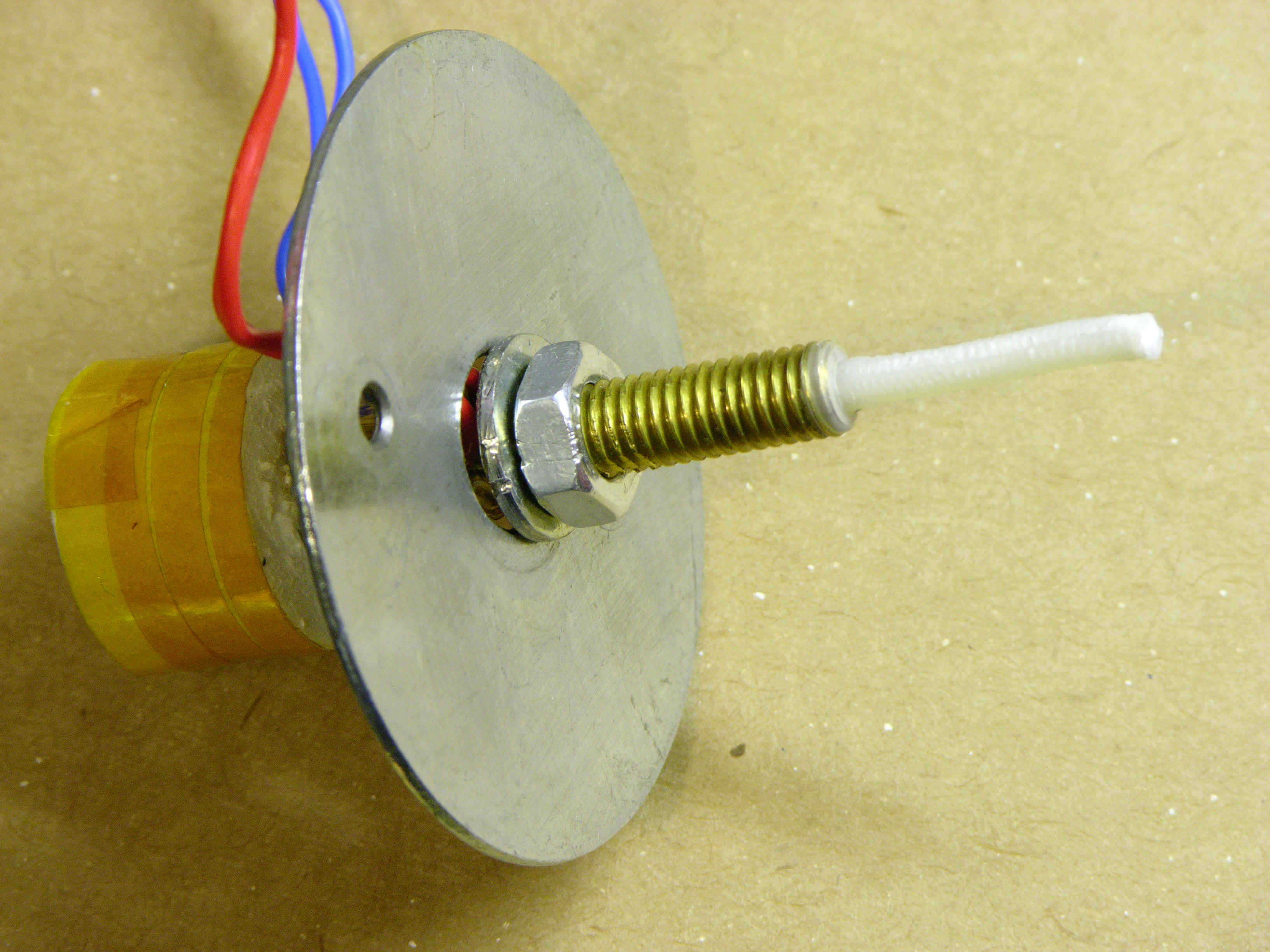
I had written about jamming my CupCake nozzle trying to extrude PLA and having to disassemble the whole nozzle to clean and rebuild it. I got new PTFE thermal barriers (the white Teflon® tube) from MakerBot, put things back together, and quickly jammed the heater with ABS, which I’d never done before.
I conversed with Nop Head about the increased force required to push filament through the heater and he pointed me to the junction between the brass heater barrel and PTFE thermal barrier. It needs to be absolutely closed, and when reassembling I’d left a tiny gap into which the ABS expanded (covering the end of the brass in the photo), interfering with smooth flow of more ABS into the brass. He gave me this video link to a vivid demonstration of the phenomenon, in which he is attempting to push filament into a heater assembly that’s wide open at both ends:
He gave me the tip to reassemble the brass heater and PTFE barrier with a drill bit of the nominal hole diameter inserted. When the two are turned together as tightly as they should be, the PTFE will begin to deform and just barely begin to grip the drill bit.
Believing the filament hole through the PTFE is metric and not owning metric drill bits, I figured the next best thing would be to use filament itself (which would be slightly undersized; but I could tighten until friction increased and then back off slightly). To my surprise, I couldn’t push filament through just the PTFE tube by itself.
Upon inspection, I discovered swarf where the little filament hole from the top meets the larger heater hole from the bottom, and this swarf was interfering so much with the motion of the filament that even after forcing the filament end past it, I still had difficulty moving the ABS filament through the tube. No wonder the heater was jamming!
I reached into the large end of the hole with a rat-tail file and used its tip to push the swarf into the small hole, then filed it free by push-filing upwards into the hole. After cleaning the PTFE thoroughly, I reassembled the heater and fired it up again.
In the past, I’ve been able to hear my stock DC gearmotor slog down when the filament reaches a certain point inside the heater, and I’ve always assumed that was due to the constriction of the nozzle. Not so, as my motor no longer slogs, and instead merrily pushes filament through like chocolate sauce dribbling out of the corner of a topping pouch! I have to assume that my original PTFE barrier had the same problem (to a lesser extent) all along, and I wonder how many others out there do too.
Thermal Gradient and Glass Transition Phase
While rebuilding the heater, I initially thought that part of my original problem must have been the top of the brass getting hot enough to melt the plastic filament that close to the PTFE, as I had always pictured the filament melting somewhere inside the brass. I’ve also read about hot-end designs with a heater near the tip and a heatsink higher up to keep the feed area cool and the plastic solid while inside it.
I thus rewound all of the nichrome near the nozzle end and thermally insulated only the tip, thinking the cooler area above would help keep the filament from melting within the PTFE.
Even though after deswarfing the PTFE, the extruder initially worked far better than it had before, it proved not to be as reliable as desired, and I did notice the filament feed beginning to bog down. I had an ongoing email conversation with Nop Head, and he gave me this fantastic explanation of the hot end, which I reprint here with his blessing:
Most of the temperature is dropped across the PTFE and the point where the plastic melts (when stationary) will be about half way between the end of the barrel and the top of the insulator. This is where it is most viscous, so it is is good that it is inside something very slippery.
Brass is about 1000 times more thermally conductive that PTFE, but the barrel has a much smaller cross sectional area, so the thermal resistances are not as far apart as that, but still considerably different.
When the filament is moving the melt point will be much closer to the top of the brass due to the time it takes to melt because ABS is also a very poor conductor of heat and has a high specific heat capacity.
It’s a shame PTFE is not transparent, as it would be a lot more obvious when things were not working.
I think when at rest the filament melts in the PTFE. When moving I think it only gets above the glass transition, so when there is a gap it expands into it and jams.
Well, heck! If that’s the way it works, it sounds like I want the brass heated evenly (at least in this Plastruder MK3 design) to keep the filament as soft as possible at the brass-PTFE junction.
I disassembled the heater yet again, this time rewinding the nichrome as evenly along the length of the barrel as possible and once again insulating the whole barrel. After reassembling, I haven’t noticed the feed motor bogging down as it was before.