Archive for August, 2006

LED Clock: Serial Communication, MAX232, and Programming the LogoChip UART

Tuesday, August 22nd, 2006

For precision timekeeping, both to set the time initially and to correct any drift that may occur, I want the LED clock to have a means to connect to a PC. Further, having serial communication available means that a PC could be used to trigger some of the clock’s special modes, like nuclear meltdown. :-) A wireless ethernet connection would be ideal; but I don’t have the time to devote to it right now, and it would add significantly to the cost. Wired ethernet and USB share the same problems. Wired serial communication is easy.

Well, supposed to be easy. The LogoChip has built-in serial communication; the hitch is that receiving data halts the running program in order to process the data. In other words, any time you set the time, the program would stop running and be unable to receive the data. That’s a drawback.

There’s a better way. The PIC chip that runs the LogoChip firmware has a built-in Universal Asynchronous Receiver/Transmitter (UART–a device to run serial communication in hardware). The LogoChip firmware doesn’t use the UART, but I can use it myself through software–and that’s exactly what I’ve done.

Level Conversion and the MAX232

There’s one trick to using the UART: RS-232 specifies ±12V for its signalling, but the PIC chip runs at 0/5V logic levels. The LogoChip gets away with interfacing to RS-232 by using a substandard transmit voltage and a resistor-based divider on the receive voltage; but there’s one more reason I can’t do that when I use the native UART: Line driver chips invert the signal so that 5V source becomes -12V on the line. The LogoChip is doing the inversion in software when it drives its hacky serial ports, but the UART requires an inverting level converter and has no facility to invert for you.

That means I need an external line driver chip (or hack something together with transistors, but I’d rather not), and that means I need a MAX232. The MAX232 not only converts from 0/5V to ±12V, but also does so without requiring ±12V power connections–it generates ±12V from a single 5V supply.

I ordered samples of the MAX232 in three different packages a while back, and received one of my samples and one of someone else’s samples. I’m trying to get Maxim to send me the rest of my samples order . . . but that’s a whole ‘nother story.

Prototyping the MAX232

A week ago, I gave up waiting on the DIP MAX232 sample and soldered leads onto my surface-mount sample so I could stick it into the breadboard. I plugged in the five 1μF capacitors it uses to step up the voltage, wired it to the LogoChip, and got pretty quick success–I could translate voltage levels going in and out. Cool!

Programming the UART

Then I tried to configure the UART so I could send data, and I couldn’t manage to get anything meaningful to go across the link. Not cool!

On the datasheet, the UART looks a little intimidating to get set up, but it’s really not too bad once you get into it. (Well, mostly.) There’s a little more to it; but you mostly enable UART mode (the pins are regular I/O pins if you’re not in UART mode), set the number of bits you want, program the baud rate generator, and drop data into the transmit register or pick it up out of the receive register.

The baud rate generator (BRG) was my sticking point. It’s set as what divisor to use of the oscillator frequency; except I couldn’t find anywhere that said whether that was the oscillator running the chip or one of the programmable timers. Turns out it’s the main oscillator–mostly.

My first problem was a think-o on the write instruction I used to configure the baud rate generator speed–I had the operand and address reversed. The proper syntax is

write <address> <value>

but I wrote

write SPBRG-9600 SPBRG

I don’t know why, but write <address> <value> just feels wrong to me. English uses verb indirect-object direct-object syntax. (“Give me the money.”) I’m pretty sure the old 8-bit microcomputer BASICs used POKE <address> <value>. So what’s my problem???

Anyway, once I got that sorted out, I had a small matter of determining the correct divisor to put into the BRG. I thought I was trying all the appropriate values from the table in the datasheet, but I could never get real text to come out on my computer. Testing was a hassle, too, as I had only one serial port available on the PowerBook, so I had to keep moving it back and forth between the programming port and the UART.

The datasheet says the divisor for 9600bps from a 40MHz oscillator is 64, but I kept getting garbage on my screen. I thought I was also testing all the different receive rates on my computer each time to see whether I was accidentally at some other rate; but even then, I could never find good data. (In retrospect, that’s especially puzzling, since I should have been at different usable data rates a number of times.) I ended up spewing dummy data (capital “U” is 01010101 in binary) from the LogoChip and looking at it on my scope to see what speed it was.

With the BRG divisor at 64, I got one bit measuring about 5.3 divisions at 20μs/div, or about 9420 bits/second. After some fiddling around, that seemed to work properly (and matches what’s on the datasheet for 40MHz), so I thought I was fine. And at that point, I was able to transmit data to the computer.

Receiving Data from the UART

Receiving is much more difficult, apparently, as I was still unable to get data from my computer into the LogoChip. It would just sit and wait for incoming data, and never actually receive it into the buffer.

Since transmit and receive share the same BRG, I knew I didn’t have a speed problem. I wondered whether the MAX232 was bad; but with my scope, I was able to confirm the flow of 5V translated data from the MAX232 to the PIC. I wondered whether the PIC was bad; but I wrote a test routine to take the PIC out of UART mode, and I was able to see changing data levels on the receive pin when accessing it manually.

What the heck???

I knew Tom McGuire had got RS-232 communication working using the UART, and so I asked him about it. He sent me some sample code (which was virtually identical to mine) and some things to check (which were all okay), and then volunteered to help me troubleshoot it. I dropped by last night after work, we hooked it up to his digital scope and saw that data was flowing where it was supposed to, we compared it to more of his code and found it was the same, and so once again, what the heck???

And then we looked at the receive error flags. I’d been wondering whether I was going to have to deal with them, but figured I’d let the master inspect my circuit and code first. But he found some other of his code that examined the receive overflow flag, and when I tested mine, I found it was set. Overflow? The UART hadn’t received any data successfully; how could it overflow???

Well, you clear the overflow bit by taking the UART out of continuous receive mode (and putting it back in). I added code to my receive routine to check for and clear the error, and BLAMMO! Instant working serial communications!

Next Steps

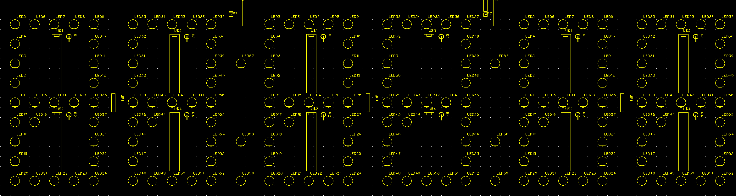
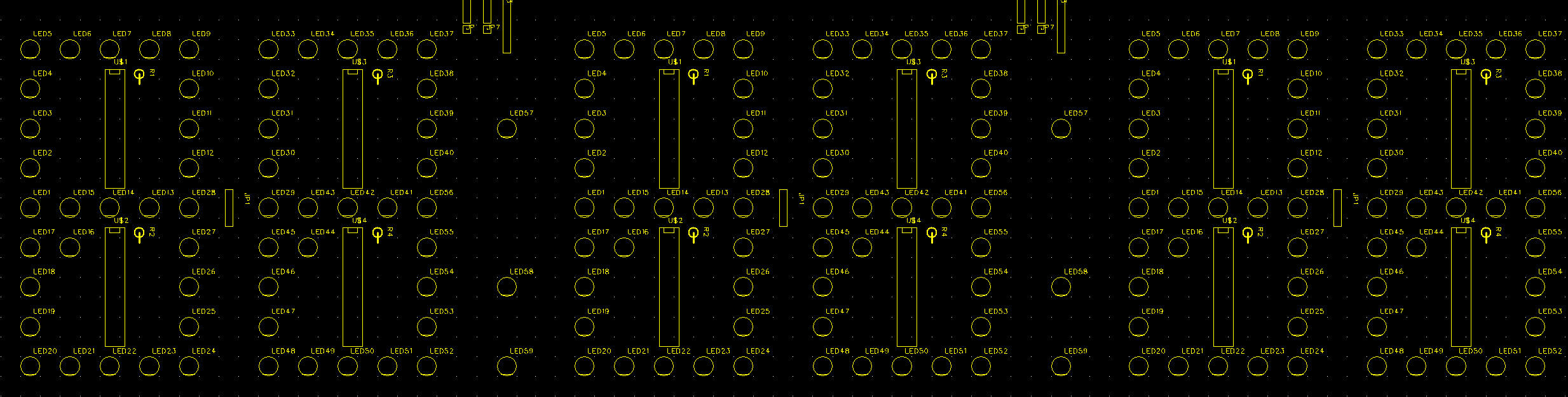
As noted yesterday, I’ve got my board for the first third of the six-digit display laid out (with the other two-thirds requiring simple clone/shift/chop operations). I added some identifying text to it last night, and I have a tentative appointment with Tom on Friday to mill the board.

Meanwhile, I now know that my serial port hardware is all okay. So even though I haven’t written the software to sync time with a PC, I can go ahead and design and build the clock’s controller board.

I should have two-digit display pictures up by sometime Saturday or Sunday . . .

LED Clock: Laying Out the Full Display

Monday, August 21st, 2006

Background and Long Delays

It’s actually been six weeks since I got my one-digit prototype working. Since then, I’ve prototyped the DS1302 real-time clock chip, done troubleshooting on some weird voltage problems, finally fixed the voltage problems, and written a demo of timekeeping with the one-digit display. I haven’t exactly been idle; but I haven’t done anything about expanding the one-digit prototype into a full display.

Well, it’s a slight exaggeration to say I haven’t done anything. About three weeks ago, I cloned the single-digit schematic in EAGLE, edited out the colons and decimal points that won’t be used in the display (between the two digits of the hour, of the minute, and of the second), and got it all to fit onto one “sheet.” But I hadn’t done anything yet about expanding the data bus to make separate latch lines for the six digits, nor had I even started working on a board layout.

Part of the problem was that the freeware version of EAGLE only does board up to about 4″x3″, which was the size of my one-digit display. I knew I was going to have to switch layout software to build a bigger display, and I’m always slow getting around to installing and learning new software. Also, I talked to Tom McGuire, who volunteered to mill a display PCB for me, and he indicated that he couldn’t do a board quite as long as the full display (15-16″). He suggested milling half, rotating around a reference point, and milling the other half, but that sounds a bit tricky to get the alignment just right.

Last week, I finally resolved myself to making the board in three sections, for HH:, MM:, and SS. That makes it easier to manufacture; and if I eventually have a means to make the whole thing in one, I can presumably paste the pieces together into one large layout.

You’re Thinking About Building a Bigger One

Through a strange sequence of events, I was hanging out at Cort’s house Saturday morning, sitting around with Cort and Shannon and Brad talking about various things. I had my PowerBook on my lap and I was tinkering with EAGLE while we visited. That’s right; I finally got back to the clock display.

I saved my six-digit circuit in case I ever want to go back to it, but copied it to a new two-digit layout and chopped out the other four digits. I cut out duplicate connectors and started wiring things together. I laid out the latch lines for all six digits, and set up the bus to have input and output connectors at opposite ends, for daisy-chaining the three boards together (if I choose).

I agonized about how to select/connect the appropriate latch line for each digit. Ideally, I’d like to have DIP headers, and you plug the jumper across the line corresponding to which digit you’re configuring. That would allow reconfiguring one digit as another for troubleshooting, to determine whether a problem was in the controller or the display. Between lack of room on the board to position a full DIP header, and the difficulty of soldering it onto the back side of a single-sided board (so it could be accessed without removing the display from the clock case), I gave in and settled on using a jumper wire to bridge from the latch bus to each digit’s latch line.

EAGLE Circuit → FreePCB Board

I had intended to use FreePCB for designing larger boards, because it looked like a nice package, and I somehow got the impression it could read EAGLE netlists (more on that later), to import part and connection information into a board layout and prepopulate it. FreePCB was designed by an engineer who was dissatisfied with available, affordable board layout software and decided to write his own. He’s done a very nice job!

Only problem is, it does not read EAGLE netlist files. FreePCB reads PADS-PCB format files, and it turns out that’s not what EAGLE outputs. Late Saturday, I tried to transfer my netlist from EAGLE to FreePCB, and quickly found out that the formats are different. Between Google and the FreePCB user forum, the only thing I could find about EAGLE and FreePCB is that the FreePCB author figures EAGLE’s format is pretty simple, and someone could write a translation utility.

So I did. EAGLE generates one partlist file and one netlist file; PADS-PCB has the two combined into different sections of the same file. I wrote a Perl script to parse the EAGLE files and translate into PADS format, and it was really pretty simple.

Except for package types. The export/import files contain an indication of what package type each device has, so the PCB software can prepopulate your layout with appropriate footprints that you just have to drag and drop into place. Naturally, EAGLE and FreePCB use different package names, so I added a hash lookup to translate those as well. Unfortunately, that’ll be the trickiest part of the program–comprehensively identifying and accommodating all the different package types.

By midnight, I had a pretty good translation going and most of the parts placed (but no traces routed) for my two-digit board–and then I noticed that FreePCB doesn’t generate outline milling information. It makes Gerber trace files and Excellon drill files, but nothing for CNC milling. Since I really wanted to be able to mill boards with Tom, and since I insist on being able to mill boards for myself in the future, I quit for the night and waited until I could talk to Tom about options.

FreePCB Board → DeskPCB CNC Mill File

I talked to Tom early yesterday afternoon. I was hoping he had a way to generate outline milling code from standard Gerber trace files, and he pointed me to a piece of software called DeskPCB. It’s $95 for a license, and there’s a time-limited demo available for free download. Generating outline code is exactly what it does–it generates “trace isolation milling and drilling” files out of Gerbers and Excellons. Shows you the original board and the mill pattern right on the screen, too, so you can confirm it’s doing what you expected.

It’s pretty slick! And that means I now have a complete path from circuit design to board production:

EAGLE for circuit design
    → export EAGLE-format netlist and partlist
    → Keith’s script to convert to PADS netlist

→ FreePCB for board layout
    → create Gerber and Excellon files

→ DeskPCB for outline milling
    → create G-code

→ LinuxCNC (née EMC) for CNC mill control
    → mill a board

Very, very cool.

You Doin’ Anything with All That Fancy Software???

Yup, sure am. I sent Jeremy a screenshot of the two-digit parts placement to stitch together into a six-digit display so we could check the spacing. My first version had .6″ between adjacent digits and .4″ between the digits and the colon.

Six-Digit Layout with .4" to Colon

From across the room, that looked like there wasn’t really enough separation to the colon, so I asked Jeremy if he could scoot them another .1″ or .2″ apart.

Six-Digit Layout with .6" to Colon

The second version with .6″ on each side of the colon looked good enough that we’re going with it. It’ll be hard to know the exact effect until we see the real thing, but this is close enough to build the first clock. If we want to change the spacing from the first to the second, it’ll be easy enough to do.

I used my single-digit layout as a reference for placing most of the traces on the two-digit, and got all of the new stuff (different power layout, six-digit latch bus) incorporated as well. By late last night, the entire board was laid out and ready to produce.

I’ll still look at it to see whether I can reroute traces to eliminate some of the jumper wires, and I still need to put design and contact information onto it–but it’s a working design that I could now produce if I chose, and that feels great! Tom has Fridays off and offered to take me to his office on a Friday to mill a board, so I’ll see whether I can set something up for this week.

Next Steps

Because the margins around the perimeter of the display aren’t the same as the inter-digit spacing, I’ll actually have three different boards for HH:, MM:, and SS. I’ve laid out the board for HH:, and it’s a trivial matter of spacing to change the board outline for MM:, and spacing and chopping the colon to make the SS. I feel I should build and test the entire HH: board before producing the other two, so I hope to assemble the first board this coming weekend.

At 174 LEDs per full display, plus 31 already used for the prototype single digit (which I don’t plan to disassemble), I’ll only have used 379 of my 498 LEDs, leaving 119 unused–enough that I could comfortably leave an entire HH: board (59) assembled as a working prototype rather than a production board. I’d be happy for it to be the first real board for a clock, but it doesn’t have to if something doesn’t work out.

I have four sample A6276 LED driver chips, enough to power two digits. I’ll need to order more before I can build the entire display.

Tom was planning to help me debug some UART problems (which I haven’t blogged yet) tonight, checking timing with his digital scope and stuff. After that’s ironed out, I can move the controller circuit from breadboard to EAGLE and lay out and produce the controller board too.

We’re getting closer!

Tektronix Logic Analyzer

Thursday, August 17th, 2006

A logic analyzer is a device somewhat like an oscilloscope, in that it displays the waveforms of electronic signals on its screen. It differs from a traditional scope in that it captures data in memory for longer study of ephemeral events rather than only displaying what’s happening in realtime (modern capture scopes do this, too); it typically has many channels (8, 16, or more plus clock and other “meta” inputs) rather than one, two, or four; and it can be configured for complex trigger events rather than only the level of a particular signal. In short, a logic analyzer does for digital system troubleshooting what a scope does for analog signal work.

I’ve never had a logic analyzer, and last spring when I started working more with the LogoChip and other digital parts, I started hankering for one. I found and bought this Tektronix on eBay for only $30 plus shipping:

Tektronix Logic Analyzer, Front

It has text-based menus, online help, and a charming monochrome green screen. It’s built almost like general-purpose 6502 luggable microcomputer, with a big stack of signal handling boards in it.

Tektronix Logic Analyzer, Interior

The only catch was, it didn’t come with any probes. I was hoping at first that all I needed was ribbon cables to fan out from the dual-row headers on the front panel, but I couldn’t find pinouts anywhere (including online). I emailed Tek’s tech support asking whether they might still have pinouts available that I could download (since they no longer sell or support this analyzer and wouldn’t be losing any money on me), and I got an incredibly helpful phone call back from them.

Their tech support representative indicated that the probes have active CMOS circuitry in them, so you need more than just pinouts; and he gave me the model numbers of three different probes that should work with that analyzer. I saved an eBay searched and waited, until a couple of weeks ago when one of them popped up and I bought it for about $25.

Tektronix P6444 Logic Analyzer Probe

There’s obviously a fair bit of circuitry in there that I wouldn’t expect to be able to duplicate, so I’m glad to have bought it. Now I still need cables to go from the probe module to the circuit being analyzed. And after I received the probe module, the seller emailed me to say that in the same box as the module, he also had these connectors that went with it; did I want them for another $25?

Tektronix Probe Wiring Assembly

Okay, if he’d included them in the auction with the module they go to, he probably wouldn’t have got any higher bids. It’s his job to maximize his profit, so I suppose he’s doing what he ought to. But I feel like a guy who just negotiated to buy an antique auto out of a farmer’s field, only to be asked whether I’d also like to buy the engine that goes with it that I have over here in the barn. Yes, sure I’d like the wires that go with the probe module you already sold me; and at the same time, no, I really don’t feel like sending you any more money for something that really belongs with what I bought the first time.

Furthermore, most of the time I’ll be using the analyzer, it’ll be with circuits on a breadboard, where I’m going to have to make my own cables terminating in pins anyway. These probe tips have really cute grippers on them that are perfect for grabbing onto classic DIP leads, but useless on a breadboard.

But I was still wavering, since I don’t know how to describe these tips well enough to save an eBay search that would pick them up, making this a rare opportunity to get something I might eventually want.

I called Cort last night to ask his opinion, and the moment he said “troubleshooting your arcade games,” I knew what the answer was.

I just sent the PayPal.

Hacking Cell Phone Displays –> Travel Route Timer?

Friday, August 11th, 2006

I just ran across Jakob Selbing’s instructions on reusing old Nokia cell phone displays via the Make blog. And I just happen to have a whole box of dead phones from that model line; and they look like the interface is the same one as in his article.

Nokia cell phone display and keypad board

This opens a number of interesting possibilities. The display is 84×48 bitmapped pixels, and it has a very simple serial communications format. Jakob’s hack reuses the entire UI (display + keypad) board from the cell phone; but the display itself unclips from that board and could be used independently, by etching appropriate pads onto and cutting appropriate clip holes into a new PCB.

My first thoughts were all the ways I could reuse just the display: for a digital thermostat I’d like to build, for status indication and debugging on robots, for status indication on a CNC drill/mill machine, etc. But this morning on the way to work, I thought of another project I would want to build into an actual entire cell phone case; leaving the keypad, display, and battery; and replacing the “phoneness” board with my own board.

Travel Route Timer

My grandfather kept meticulous logs of times and mileage whenever my dad’s family travelled, and all of Neufeld relatives count things. Seriously, when you get together with Neufelds, it’s perfectly common to hear us caculating how many bricks are in a wall, or estimating how many folding chairs are on the rolling racks in the corner, or determining how big the room must be based on a count of ceiling tiles.

Some ten to fifteen years ago, I was driving to Tulsa as much as once a month to visit a friend who had moved down there. (You can see where this is going already.) It was about a three and a half hour drive, and I thought, wouldn’t it be great to have a little pocket device with some buttons and timers that would show me how long I’d been on the road, how far to the destination, and how far to the next landmark.

I figured I’d enter landmarks on the device OR in advance, then have a list displayed on the trip timer and hit the “HERE” button as I passed each one. If there were room on the screen, it could show me landmark countdown time as well as remaining trip time. It’d need a set of buttons to indicate if I stopped at a rest stop or restaurant, to categorize that as non-driving time that might get counted toward estimates of total trip time but not toward time to next landmark. It would average up my actual road times every time I made the trip, and could develop more and more accurate predictions of trip time and variance. Etc., etc.

At first, I had in mind that it would be a custom gadget. Then when Palm computers were invented and I got a Visor, I always hoped to write a PalmOS program to do it. Alas, it never happened.

Now I’m seeing a new opportunity. Cell phones are a decent size to carry around, and they’re made relatively tough compared to other experimenter case options. The Nokias have an adequate display that I now have information on how to use, and there’s a keypad right there for indicating landmarks passed and maybe even entering the names of new destinations and landmarks. They even come with batteries and chargers!

Plus the idea of taking out the middle PCB of the cell phone–the board that actually makes it a cell phone–and replacing it with a board to do something completely different really appeals to me. The only drawback I see is lack of an obvious way to sync it to a PC for offline landmark entry and persistent data storage and analysis.

Hmm . . .

Addendum

The specific incident this morning that made me think of this project was wondering how fast I was going. I’m test-driving a vehicle today, and it just had the speedometer sensor replaced. I drive the speed limit and am used to getting passed on the highway, but this morning it seemed as though I was getting passed a lot more than usual.

I’d want this device to have a speed-check mode, in which I press the button every time I pass a mile marker, and it calculates and displays how fast I’m actually going.

Rotary Phone == Alarm Clock ?!!!

Sunday, August 6th, 2006

Independent of the LED clock project, I’ve been thinking of building myself a new alarm clock. . . . More on that in a while, after I receive some prototyping materials I’ve ordered.

But tonight, watching The Animatrix, I got the wacky idea of making an alarm clock that uses a rotary phone dial for input to set the time. Pick up the receiver, dial the four digits for which you want to set the alarm, and bingo! Good to go.

It kind of escalated from there, to a fairly-well fleshed out rotary telephone alarm clock. Consider:

  • Rotary dialing to set time and alarm.
  • Mechanical bell ringer for alarm–you won’t oversleep that baby!
  • Pick up the handset for alarm functions. Take the phone offhook and dial a number to set the alarm. Alarm rings, lift the handset to silence the alarm.

Primo! Of course, I still have to work out a few details:

  • How do you tell the phone that you’re setting the time? It could accept dialing while the handset is on hook; but that just begs for people who walk up and twiddle with it to be randomly resetting the time. Maybe indicate it with a special dialing sequence like starting with 0 or 411?
  • How do you display the time? Gotta have a four-digit display on there somewhere, and that’s totally gonna mess with the aesthetic. Oh well. Probably have to mount it through the lower front of the phone.
  • How do you snooze versus shutting off the alarm for the day? Leave the handset offhook versus putting it back on?

A rotary multi-line phone with lighted buttons across the bottom could be fun, as would a speech synthesizer to read the numbers to you in the handset as you dial.

Spark Fun has done a rotary cell phone, and they wrote up the processes of interfacing to the rotary dial and switchhook and driving the ringer. Of course I’d write to ask permission first, but I’m sure I could use their work to build the pertinent sections of my clock.

Now I just have to get my hands on a couple of old rotary phones . . .

LED Clock: DS1302 + A6276 = Visible Demo

Sunday, August 6th, 2006

After the big victory of getting a bright blue digit working, and the lesser victory of getting the RTC chip communication working, plus some time away from home, I’ve been stalled on the clock for a while. I gave myself a kickstart yesterday by connecting both the DS1302 timekeeping chip and the one-digit display at the same time, and writing some demo code to flash the current hour and minute one digit at a time.

Enough Controller Pins

I had written previously about whether I was going to have enough pins on the controller to run all the different lines I need to hook up. Now that I’m a little further along in development (working prototypes of different parts, settled on the choice of RTC chip), I think I’ve nailed down the exact pinouts I’m going to use:

Pins Subsystem Signals Function / Notes
A0 RTC CE enable
A1 RTC I/O I/O
A2 RTC SCLK data clock
A3-5 unused . .
B0 display SDI data input (to display)
B1 display CK data clock
B2-7 display L0-5 data latches for six digits
C2 display /OE display enable
PWM output for software dimming of display
C6 UART TX transmit
C7 UART RX receive

It seems positively serendipitous that I’m able to use the built-in UART for time synchronization and the one free PWM output for software display dimming without overriding any of the LogoChip’s firmware functions, and everything still fits. I even have a few pins left over, if I think of something else I need to add.

Port A and Analog Inputs

I’d had trouble using A0-2 to control the A6276, and Muaz (in a comment) and I both assumed it must have something to do with the analog inputs (even though I was only outputting to the pins). Looking over the PIC18F2220/2320/4220/4320 datasheet, I can’t find any reason for that–when the pins are set for output, they’re simply outputs like any other pins (although the A/D converter is available at any time, so you can always measure the actual voltage on the port regardless of mode or direction–how curious).

However, since I’ve now moved the RTC to port A (so port B can be used contiguously to drive the display), I needed to be able to use the pins as digital inputs; and I was pretty sure they were configured for A/D when in input mode.

Indeed, the LogoChip language reference says that pins A0-3 and A5 are configured as analog inputs on boot. So I studied the PIC datasheet and wrote a function to configure them as analog or digital as desired. I had guessed that there’d be a bit-wise control register like the I/O port tristate registers; but in fact, there’s a register nybble that simply contains a count of how many analog ports you want; and the PIC makes the right number of ports analog in order from the list A0, A1, A2, A3, A5, E0, E1, E1, B2, B3, B1, B4, B0 (with the E ports only available on 4×20 chips); which is kind of a clever way of doing things.

Here’s my library routine:

  • ad.lib – Library routine to set number of analog inputs

Here’s the code:

;   Keith Neufeld
;   05-Aug-2006
;
;   LogoChip library to configure the number of analog inputs, which
;   start on port A and work into port E (on the 4320) and port B:
;
;       A0, A1, A2, A3, A5, E0, E1, E1, B2, B3, B1, B4, B0
;
;   (PIC18F2220/2320/4220/4320 Datasheet, p. 4)
;
;   Lines set as analog inputs also function as digital outputs,
;   depending on the settings of their port's tristate register.  Lines
;   not set as analog inputs function as digital I/O.
;
;   The PIC sets all possible inputs to analog on powerup (Datasheet
;   p. 50), which the LogoChip firmware overrides to five (A0-3 and A5;
;   LogoChip Language Reference, p. 7).

constants [
    [ADCON $fc1]                        ;   port A control register
        [PCFG-MASK #00001111]           ;       mask for port config bits
                                        ;   Datasheet p. 214

]

to config-analog-lines :number
    if (:number < 0 or :number > 13) [  ;   only 13 lines possible
        stop
    ]

    ;   Preserve high nybble and set low nybble to %1111 minus the desired
    ;   number of analog lines.
    ;
    ;   *ADCON = (*ADCON & !PCFG-MASK) | (PCFG-MASK - :number)
    write ADCON (((read ADCON) and (not PCFG-MASK)) or (PCFG-MASK - :number))
end

I told a little fib–the PCFG (port config) nybble actually contains the bitwise inverse of the number of lines configured as analog, as the code shows.

Integration

So . . . I set the PIC for 0 analog inputs, moved the DS1302 interface to A0-2, and it still works fine. Glommed together the demo code for the DS1302 and one-digit display:

constants [
    [spew-on-msec 200] [spew-off-msec 30]
]

to ds1302-a6276-time
    ds1302-read-clock

    a6276-display-digit nybble-high ds1302-get-hour 0 0
    mwait spew-on-msec
    a6276-off
    mwait spew-off-msec

    a6276-display-digit nybble-low ds1302-get-hour 0 0
    mwait spew-on-msec
    a6276-off
    mwait spew-off-msec

    [. . .]
    a6276-display-digit nybble-high ds1302-get-minute 0 0
    [. . .]
    a6276-display-digit nybble-low ds1302-get-minute 0 0
    [. . .]

And I now have a nice little demo which, upon power on, flashes the digits of HH:MM up onto my display, one at a time, with no host computer attached. Perfect.


It’s a little hard for me to read the digits in the video, due to some combination of my wireless connection, the persistence of my PowerBook LCD, and the low CPU power. But I tweaked the timing pretty carefully to make sure each digit displays long enough to register what I just saw, and that the inter-digit blanking is long enough to distinguish repeated digits. (I want the digits to flash fast, but I’m not trying to build a persistence of vision project.) It looks pretty good on my wife’s PC where I dock the camera to upload and preview the video clips, so I hope the web video okay for everyone but me. :-)

Code Cleanup

Right now, I have DS1302 and A6276 code split off into separate libraries (good), but the actual port pins hardcoded into the libraries (bad). That means when I change my mind about where to plug something in, I have to edit the library code–and that means if I’m using the library for more than one project, I just broke the other programs, so it’s not really a library.

What I really need, linguistically speaking, is lambdas–the ability for a function to return an anonymous function (or function pointer) that has parameters of the generator function coded into the returned function as constants. That is, I’d call

setrtcfunc ds1302-init porta 0 porta 1 porta 2

and now rtcfunc contains a function I can use to access the DS1302 that’s on A0-2.

Aw, heck, I admit what I really need here is an object generator and to use method calls against it to perform further operations; but I hate OO faddists and would much rather sound cool talking about functional languages.

At any rate, much to my surprise, :-^ LogoChip Logo doesn’t support any of those things. So I’ll settle for only being able to use one DS1302 per PIC (which for me is like, uh, pretty realistic); and I need to write an init routine to stuff the port selections into local (er, global) variables so the library is really general-purpose again. But that means putting code into all the function calls to make sure that the port selection has been initialized and aborting if not, and that means deciding whether/how to alert the caller that something went wrong, and that means more thinking, and I’m not so much in a thinking mood right now.

I’m Waiting On . . .

I have a MAX232 RS-232 line-level driver on the way to interface the PIC’s UART to the PC. Once I get that, I’ll breadboard it, write proof-of-concept code to show that I can make the PIC talk to a PC without the LogoChip halting its program to listen (like it does on the LogoChip’s software-based communications and reprogramming port) so I can later write PC time synchronization code. Then I’m ready to lay out the daughterboard for the controller, W00T!

I’m still fussing with expanding the single-digit display into the full six-digit. I made the single-digit display with only a single latch line (and I need one for each digit of the full display) and power traces that are totally inadequate for the ~4A the full display is going to draw. I’ve cloned the digit six times over on the schematic, but haven’t finished touching up the latch and power lines.

And then I’m going to have to learn FreePCB, because EAGLE Free/Light only does boards up to 80x100mm (~3.2×4″) and even EAGLE Standard ($200 each for the circuit design and board layout modules???) only does 160x100mm (~6.3×4″); so I’d have to go up to EAGLE Pro ($400 each for design and layout?!!), and that ain’t gonna happen.

Time to learn FreePCB, which costs $0, makes boards up to 60×60″, recommends using EAGLE for circuit design and export . . . and only runs on Windows. Sigh.