Archive for March, 2006

Ultrasonic Rangefinder, Part II: Receiver

Sunday, March 26th, 2006

Last night, I prototyped the transmitter circuit; today, I worked on the receiver. Coe’s design uses a two-stage op-amp circuit, with AC coupling on the input from the transducer to the first stage, to amplify the received signal before sending it to a comparator. I wanted to do the same, but I prefer to run from a single supply voltage, so I used an LM324 and added voltage dividers to bias the signal up to 2.5V.

First, I powered up the circuit from last night and measured the receiver’s signal on my scope. With the transmitter and receiver about 2” apart, the receiver signal was about 2V peak-to-peak, attenuating to about .5V p-p at 2’. If it continues to attenuate by a factor of 10 every 2’, then to measure distance out to 10’ (round trip of 20’), the received signal would be 2 * 10-10, or .2nV. Let’s hope that’s not the case!

The Circuit

Each stage of the amplifier circuit is taken directly from the LM324 datasheet, “AC Coupled Inverting Amplifier” (although the two stages are DC coupled). The receiver’s signal is AC-coupled to the first amplifier’s inverting input, with a 2.5V bias to the non-inverting input.

Ultrasonic Receiver Amplification Schematic

I’m not sure why C1 is needed on the bias voltage divider, but the output waveform was considerably cleaner with it than without, so I left it in. I also don’t know what RB does, and Forrest Mims’ Engineer’s Mini Notebook on op-amp circuits didn’t show it but the datasheet did, so I left it in as well.

Values

The bandwidth-gain product for the LM324 is 1MHz, so a 24kHz input means the maximum possible gain is about 41.7. The gain is set by the quotient of the feedback and input resistors, and it worked very naturally to select RF = 1MΩ and RIN = 24kΩ.

According to Mims, CIN should have a value of 1 / (2π flow RIN), where flow is the lowest frequency to pass the filter. This gives CIN = 1 / (2π 24kHz 24kΩ) ≅ 280pF–except the first time around, I mistakenly calculated using RF (1MΩ) instead of RIN (24kΩ), and got 6.6pF. I had a 10pF on hand, so I substituted it; but it was still far too low a value, as will be seen shortly.

I breadboarded the circuit on my workbench and measured about .04V peak-to-peak directly from the receiver element, with both transducers pointed at the ceiling. (That was about an 8’ round trip, so my dire prediction of .2nV was fortunately not the case.) Next, I measured only about .08V p-p at the output of the first amplifier stage, so obviously something was wrong. It was at this point that I added C1, which brought the amplifier output to about .1V and cleaned it up dramatically–but with a gain of 40, it should have been more like 1.6V.

I was suspicious about the value of the AC coupling capacitor, CIN, and began substituting different values for it, with the following results:

Condition Signal Amplitude
direct transducer output .04V
CIN = 10pF, C1 absent .08V
CIN = 10pF, C1 = 10uF .1V
CIN = 100pF .5V
CIN = 1nF .6V
CIN = 10nF .6V

It looked like I must have miscalculated by an order of magnitude (at this point, I hadn’t yet caught my frequency error in the calculation), and 100pF was probably close to the best valued, but still a little too far down the knee of the filter’s response curve. .6V output was still a little low for a gain of 40, but within a range I was willing to accept, given that I was estimating the values by counting hashmarks touched by a dirty, wiggling waveform on my scope. I put the 1nF back in and called it good.

Second Stage

After honing the values on the first stage of amplification, the second stage was easy–just more of the same. I used all the same values, but omitted the AC coupling capacitor, since I’m happy to DC-amplify around the 2.5V bias. The second stage gives me a trapezoidal waveform (clipping both the top and bottom of the transducer’s sine wave) running rail-to-rail of the LM324′s advertised output capacity–from 0V to about 4V. Tomorrow I need to run that through a comparator to clean it up just a little more, and then steal John’s capture/compare LogoChip code to start timing the echoes.

DIY Ultrasonic Rangefinder

Saturday, March 25th, 2006

Ultrasonic rangefinders detect objects and measure distance the same way as a bat: Emit a high-pitched “ping” and measure how long it takes the echo to return. The speed of sound in air is nearly constant (ignoring slight variations due to air pressure and humidity), so the time from ping to echo translates directly into the distance to the object.

I’m interested in ultrasonic rangefinders for both hobby robotics and our TechArt final project. They’re available commercially, but $25 each adds up pretty fast if you need multiples to establish a view all around a bot or across the wide front of an art installation. All Electronics has transducer elements for $1 each in quantities of 10 or more, so I ordered a batch of them in hopes of building a rangefinder myself. At $2 each (two transducers, for send and receive), I can add a fair bit of supporting circuitry before hitting the $25 mark.

The Plan

I’m basing my circuit on a design by Gerald Coe at http://www.robot-electronics.co.uk/htm/srf1.shtml, and adapting it for different design goals. His circuit uses a dedicated PIC to provide the oscillator, a MAX232 to generate 16V to drive the transmitter, and 40kHz transducers. For now, I want to run my rangefinder from an existing LogoChip that’s also doing other work, avoid the complexities the MAX232 adds, and use transducers with a different nominal frequency. Later, I might build separate modules intended to stand alone and run with very low power.

Initial Testing

According to a comment on the All Electronics page for the transducers I ordered, they run at 24kHz. The first order of business was confirming that operating frequency.

I hooked my function generator to my frequency counter and scope and dialed in 24kHz, to make sure I was in the neighborhood before connecting the transducer. I then connected one transducer to the function generator to serve as the transmitter (with the frequency counter still attached), and the other transducer to the scope to serve as the receiver.

When I pointed the transmitter at the receiver, a signal showed up on the scope; when I pointed it away, the signal abated. I could bounce it off my hand and receive it, but not off the ceiling. (I’m guessing the elements weren’t aimed well enough and/or the amplitude wasn’t high enough.) And changing the oscillator frequency confirmed that 24kHz is indeed optimal.

So the project is at least possible. That’s a good start!

Connecting the LogoChip

I really didn’t feel like disassembling my balance-bot project, so I’m sure glad I bought several PICs! I built up a breadboard with another LogoChip on it and verified operation. Then I took my motor-control PWM code and cleaned it up to generate a single frequency signal.

Testing with my frequency counter and scope hooked up, it looks like I need timer 2 with a prescalar of 1 and a period of 82 to get as close as possible to 24kHz. Hm, 82 * 24k ≅ 2M, which tells me that I really don’t understand what timer 2 is using for an input clock. Wait–yes, I got it. The PIC has an internal 4x increase in oscillator speed, so the 2Mhz timer oscillator leads to the 10Mhz clocking.

Driving the Transmitter

I first tried powering the transmitter element with an NPN driver, for simplicity and to allow experimentation with the drive voltage:

Ultrasonic Transducer Driver using NPN Transistor

I connected the receiver element to my scope to detect the signal, and was surprised to detect nothing. I looked back at Coe’s schematic and noticed that he drives his transmitter in a push-pull arrangement using the MAX232, so I scrounged around for something with totem-pole outputs that I could use to test. The quickest thing I could come up with was a 7404:

Ultrasonic Transducer Driver using LS7404

And this time, I did show a received signal on the scope, albeit a slightly weak one; so I guess the push-pull drive is necessary.

I’m not satisfied being restricted to a 5V drive, because Coe specifically mentions using 16V to get adequate detection at greater range. However, I’m not sure I have anything on hand that will do exactly the right job and which I’m happy using. None of the options quite work out:

  • The 74xx chips with “high-power output” and 754xx peripheral drivers run open-collector, and I don’t see a good way to use that to provide push-pull.
  • The 754410 H-bridge driver adds about $2 to the cost–not bad, but I’d rather avoid it if I could.
  • The MAX232 adds about $1 plus numerous supporting components–and Coe mentioned that it generates enough noise that he shut it down after each ping to keep it from interfering with the echo detection circuitry.

I’ll probably prototype with the 754410 since I have some on hand, and keep looking for other options.

Robot Throwdown!

Thursday, March 23rd, 2006

I was joking around with a coworker asking how soon he was going to switch a Unix server to use LDAP for login authentication instead of the local password file, and after seeing my two-wheeled balance ‘bot crash and dive yesterday, he replied:

When a two-wheeled balancing robot scoots into my office and tells me to do so!

Then after I asked whether he was willing to commit to that promise, he backpedaled and followed up with:

I sense trickery, either that or motivation to expidite the process.

Just in case I better clarify, lest some off-the-wall intrepretation of the rules takes place.

I, Garrett Marks, will enable LDAP authentication on zion for system accounts when,

A two wheeled, self powered, balancing robot enters my office under its own power (the door may be held open for the poor fella) and audibly asks me to “enable ldap authentication on Zion, please” via some sort of electronic powered sound producing system (no it can’t just hand me a post-it note). The robot must be assembled by Keith Neufeld.

And later, another caveat:

A1: The robot must be standing upright when it delivers its request.

Okay, Garrett; you’re on!

Edge-Lit Scratched-Character Displays

Tuesday, March 21st, 2006

Ted Johnson's Edge-Lit Clock

Okay, I’m not much for filling blogs with links to blogs that link to other blogs ad infinitum . . . but this is just too cool. Ted Johnson built a clock out of acrylic sheets with runes scratched into them, edge-lit with LEDs, and stacked to show multiple different characters per position.

Ted Johnson’s Project

EAGLE for Circuit Design and PCB Layout

Tuesday, March 21st, 2006

I’ve been looking for circuit design and PCB layout software for a long time, and in the past couple of weeks I’ve settled on EAGLE. I’ve used it to draw up the most recent schematics here on my blog. Its key advantages for me are:

  • There’s a freeware version. I don’t do enough circuit design to justify paying a lot of money for commercial software–especially software that I haven’t got to try first.
  • It can output netlists from it circuit design module to use with other PCB layout software, and it can output Excellon drill files to use on my friend Joel’s CNC drilling machine.
  • It runs on Windows, Mac, and Linux–and I expect to use all three versions regularly.

To understand why I like it so much, though, it’s worth running through the other software I’ve used.

Electronics Workbench: Multisim and Ultiboard

I got a student copy of Multisim and Ultiboard with my electronics textbooks in 2004. I used it a lot in class, and I think it’s fantastic for doing circuit simulation. It blows me away that it’s even possible to do that level of analysis and simulation on a commodity PC, and I really appreciate Multisim for what it does.

Unfortunately, I also had a not insubstantial list of complaints:

  • The Multisim (circuit design/analysis) UI is pretty glitchy. I had a lot of trouble selecting the component I wanted to move; I’d box-select a group of components and drag them, and parts would get left behind (and disconnected); etc.
  • I had trouble getting the hang of the UI for Ultiboard, the board layout software. I don’t remember exactly what I didn’t like, but I know I gave up in frustration pretty quickly.
  • Worst, though, is that the installation uses a nodelocked license. I installed the software on two PCs in Pittsburg, and when I left, I completely uninstalled it. I’m now within the rights of my license to install it on another PC–but I’ll have to call EWB to get another install code, because I’ve installed it too many times to get a new code automatically.
    So I feel like the next time I install it, I need to be ready to put it onto one PC where I’m going to leave it forever–because how many more times can I call them and tell them (truthfully, but they have no way of knowing that) that I’m moving it to yet a different PC? The offshoot of that is that I’ll probably never install it again.

PCB123

I had used ExpressPCB (next) a long time ago, and while I was searching for it recently, accidentally installed PCB123 instead. Like ExpressPCB, PCB123 is a company that makes small quantities of PCBs for prototyping and hobbyist use, and gives away the software to design the circuit and layout the boards. I don’t even remember what I didn’t like about PCB123–I just know that it took me about five minutes to realize it wasn’t ExpressPCB and I wasn’t willing to learn to use it.

ExpressPCB

LogoChip in Altoids Tin Schematic
LogoChip in Altoids Tin Layout

I had been happy with ExpressPCB for a long time. They’re a board manufacturing house, and they figured out long ago that if they give away circuit design and board layout software, they’ll entice people to use their services.

I think they walk a delicate line trying to decide how much functionality and interoperability to put into their software–too much and people might use their software and then have boards manufactured elsewhere; too little and people will get frustrated using their tools.

In my case, despite finding their UI to be the absolute best I’ve handled, the functionality is too low, and I’ve moved away from their software. With a little more functionality, I’d still be using their software, and I’d turn straight to them when I need a board commercially produce.

First, I have to sing their praises:

  • I found the UI to be fantastic, in both the circuit design and board layout sections. The toughest operation for this type of software seems to be selecting an existing part to move, and I would almost always get exactly the part I was trying to select; it was easy to reselect a different part in the cases when I didn’t get it on the first try.
  • Their board layout software has a netlist checker, so you can see which pins need to be connected. (However, see “ratlines” below.)
  • The UI just has a good “feel” to it–everything handles very nicely.

However, its drawbacks were serious enough for me to move away from it:

  • Foremost, because the software exists entirely to get you to buy boards from ExpressPCB, it has no facility for exporting drill files. I’m drilling boards on my friend’s machine, drawing traces by hand, and etching in a plastic tank–I pose no threat to ExpressPCB’s business–but I can’t use their software to automate my homebrew process. It can’t be made to meet my needs.
  • ExpressPCB doesn’t prepopulate the PCB layout with the components used in the schematic. You have to add and label each component individually. That’s time-consuming and error-prone.
  • ExpressPCB doesn’t support ratlines indicating netlist connections. Yes, it can highlight solder pads that need to be connected–but it’s easier to lay out traces when you have ratlines indicating all of the connections that need to be made.
  • The board layout UI is a little over-eager to merge connections. I’ve had to scroll the entire board off the screen when calling up a new part to add, because with the board on the screen, the part got merged into existing traces before I could even select where the part was to be placed. Similarly, I’ve had entirely unrelated traces merged together because I was dragging a set of parts to a different area of the board, and corners of traces I was dragging (and would have rerouted as the next step) landed on top of other traces.

The biggest issue, of course, was being able to produce the interchange formats I needed–but the other issues served as cautions while looking at other packages.

FreePCB

FreePCB is a really nice-looking package, an amazing programming accomplishment from a single individual, and free of cost but not open source. I like it a lot, and I expect to use it for larger boards in the future. It’ll import component and netlists from other software, and it’s what led me to EAGLE for circuit design.

A few observations:

  • It doesn’t have any corresponding circuit design software. That’s means there’s no way to automate back-annotation when changing a design during PCB layout, and the coupling for forward updates isn’t as tight as with some of the other packages.
  • It’s extremely tedious to lay out a board from scratch without an accompanying parts list from a circuit design package. FreePCB is intended to be used in conjunction with circuit design software, and I’d want to use it that way most of the time. However, I was trying to lay out a one-component, two-connector board without having drawn the schematic, and found it prohibitively difficult to do.
  • It has ratlines, a nice feel, decent export capabilities, etc. It was designed by an engineer–it was made to work well.

EAGLE is a little smoother for me to use, but the free version has some restrictions that I may eventually run into. When I do, I plan to use FreePCB for those boards.

Hand-Created Drill Files

For a 2″ x 2.5″ board with a PIC microcontroller, RJ-45 connector, LED array, lots of sockets, and supporting passives; for the one-component board I mentioned above; and for a couple of other boards I’ve worked on since then; I’ve drawn the circuit (and sometimes the PCB) in one package or another, and then laid out the drill file by hand. It’s not hard–key in a zillion (x,y) coordinates, plot the file in gnuplot to make sure it looks right, use a small Perl script to translate to rudimentary Excellon code, and drill it.

It’s a dumb way to have to do things, but it got me a drill file that I couldn’t get out of ExpressPCB, and it got me a layout that I didn’t have time to figure out how to do in FreePCB. I’d rather not make a lifestyle of it, though.

EAGLE

ADXL202E Carrier Board Schematic
ADXL202E Carrier Board Layout

Which brings me to EAGLE, the software I think I’m going to be using for a long time to come. It outputs the formats I need, it runs on all the OS platforms I use, and a slightly restricted version is available at no cost. The freeware limitations won’t impact me for quite a while: only one-sheet schematics, only two-layer PCBs, and PCBs no larger than 4″ x 3.2″. I’ll hit the last one first, and I’ll use FreePCB for layout when it happens.

I do have a few complaints about the UI:

  • It’s often very difficult to select an onscreen part to move to a different location. I’m starting to resort to drawing a select box around the interior of the part in order to select it and nothing else; I much prefer the click-click-click to cycle through overlapping parts. I think there’s a right-mouse trick to cycle in EAGLE, and I need to learn it.
  • Speaking of right-mouse, too much of EAGLE’s functionality depends on it. I use the right mouse button nonstop when I have one, but my PowerBook doesn’t.
  • The screen doesn’t automatically refresh objects when other objects have been covering them and are removed, at least not in the X11 versions. Yes, I can hit F2 to redraw the screen, but it’s often really messed up until then.
  • EAGLE seems to have serious problems performing unintended merges during component rotation operations–I have PCB traces that get stuck together and I have to reroute by hand. Worse, that situation seems to corrupt the netlist, because it changes the ratlines. I’m stuck with leftover ratlines that disagree with their traces, and no way to correct them. This is very problematic.

But mostly gratitude at finally finding software that does so many things right:

  • Pretty good coupling between the schematic and board layout sections, including prepopulating components and ratlines
  • The ability to export a netlist to use in a separate board layout program
  • The ability to export drill files in Excellon format to drill my own holes

LogoChip and PWM: Bidirectional Motor Speed Control

Tuesday, March 21st, 2006

Early last week, I was working on expanding my PWM motor speed control to be able to reverse directions. I had the PWM output from my LogoChip’s PWM subsystem, and I wanted to add another line to indicate whether to spin the motor forward or backward.

Because I’m using the 754410 motor driver chip, I need to apply the PWM signal to the pin corresponding to the direction I want the motor to turn, and keep the other 754410 input pin grounded. That means I needed to translate from (speed, direction) to (move forward, move backward). I have lots of digital logic chips lying around, so I knew I could put something together.

Ideal Schematic

Ideally, if I had all the gates I wanted on a single chip, it’s this simple:

Ideal Motor Direction Control Schematic

(Pardon the truncated labels on the right side–EAGLE did that for me in the PNG export.)

I’m using a direction of 1 to mean forward and 0 reverse. So here’s what the schematic means:

  • If the PWM speed signal is on and Direction is 1 (forward), activate the Forward output.
  • If the PWM speed signal is on and Direction is 0 (reverse), activate the Reverse output.

I could have done this with a 74*08 quad AND gate and a 74*04 hex inverter, but that’s two chips. It offends my sensibilities to use two chips when one would suffice, plus I don’t have a lot of room to spare on my LogoChip breadboard. So I looked for something better.

74LS138

I was looking for a chip with a data input and address input(s) to select which output line the data was routed to, and the closest I could find was the 74*138. The ’138 is 3-to-8 decoder/demultiplexer, meant to decode three lines of an address bus into eight enable inputs for memory or other chips: You supply a three-bit address to its inputs, and it activates the corresponding one of its eight outputs.

This wasn’t exactly what I needed, but there’s a trick I figured I could use. I applied the Direction signal to an address input, to select which output would receive the PWM signal; then I applied the PWM signal to one of the enable inputs. In theory, that means that both outputs would be inactive any time the PWM speed signal was off, and the appropriate output would be active when the PWM speed signal was on.

Motor Direction Control with 74LS138

Unfortunately, EAGLE’s circuit symbol for the ’138 is a block diagram that doesn’t illustrate the internal logic, but here’s what’s going on. Direction is applied to address line A, which will select output Y1 (Forward) when Direction is 1 (forward) and output Y0 (Reverse) when direction is 0 (reverse). And the PWM speed signal is applied to active-high enable line G0, to activate the appropriate output whenever it’s high. The other enable lines are active-low, so they’re tied to ground to be active all the time.

But you’ve probably noticed that it’s still a two-chip design–there are two inverters off to the right. Unfortunately for this project, the ’138′s outputs are active-low. Most memory chips have active-low enable inputs (it makes it easier to gang together open-collector selection circuitry), so naturally the ’138 provides an active-low output. In order to get the active-high signals that I wanted to feed into the 754410 motor driver chip, I had to invert the ’138′s outputs, and that meant adding another chip. I did build and test this circuit as a proof of concept, but I still wasn’t satisfied, and kept looking.

As a bit of an aside–I could have used active-low signalling to drive the 754410. It’s an H-bridge driver chip, so it powers the motor whenever it has different inputs. When the inputs are the same–low or high–the motor doesn’t run. However, I’m guessing there’s slightly more power consumption when both inputs/outputs are high, and I wanted it to draw as little power as possible in the quiescent state, so I was determined to come up with a circuit that would provide active-high signalling.

One other note–I tied both inputs to ground with pull-down resistors. As long as the LogoChip is providing outputs, these are irrelevant–but when the LogoChip first powers up, its ports are configured as inputs and don’t provide a valid TTL signal to the ’138. The motor was freaking out (that’s the technical term) when I’d reset the LogoChip, so I added the pull-downs for power-up sanity.

74LS153

The 74LS153 is my final, one-chip solution. It’s a dual 4-line to 1-line data selector/multiplexer, meant to do exactly, uh, the opposite of what I need: It picks which of four inputs to send to the output. But that’s okay–there are two selector/multiplexers in one package. That means I can use one multiplexer to select whether the PWM or nothing goes to the Forward output, and the other to select whether nothing or the PWM goes to the Reverse output. Looks a little somethin’ like this:

Motor Direction Control with 74LS153

Again, EAGLE renders the ’153 as a block without exposing its inner workings, so explanation is in order. Inputs A and B are the address lines (think A0 and A1) to select which data input will be delivered to the output. Note that A and B select for both multiplexers at the same time, so I don’t have to wire to separate address lines for the two multiplexers. Input B (address line 1) is tied to ground because I always want it 0–I’m only working with the first two possible inputs. And the active-low enable inputs are tied to ground, because I always want the chip enabled.

The first selector has the PWM signal at its 0 input (1C0), ground at its 1 input (1C1), and its output (1Y) feeding the Reverse driver. So when Direction is 0 (reverse), the first selector will pick input 0 (PWM) and feed it to the Reverse input of the motor driver. When Direction is 1 (forward), the first selector will pick input 1 (ground, or nothing) and feed it to the Reverse input of the motor driver.

Likewise, the second selector has ground at its 0 input (2C0), the PWM speed signal at its 1 input (2C1), and its output (2Y) feeding the Forward driver. When Direction is 1 (forward), the second selector routes input 1 (PWM) to the Forward motor drive pin. When Direction is 0 (reverse), the second selector routes input 0 (ground) to the Forward motor drive pin.

Because human minds are forward-centric (there’s a very interesting section of linguistics that studies which word out of pairs of opposites has connotations of dominance: forward/reverse, up/down, hot/cold, etc.), it would seem to make more sense to use the first selector for the forward drive and the second selector for reverse. But I wanted Direction == 0 to activate the first selector and Direction == 1 to activate the second, and because I made Direction == 1 for forward, it worked out like this.

I added pull-down resistors again–different values this time, based on the datasheet and application notes. And the circuit works, in a single chip! Yeah, the ’153 is overkill for this application–but I can’t find a simpler single chip that’ll do the job. I could do it with a PAL and have room left over for other tasks; but in the absence of a need for other logic in this project, that’s even more overkill.

Finis.

DIY Logic Probe

Monday, March 13th, 2006

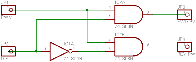
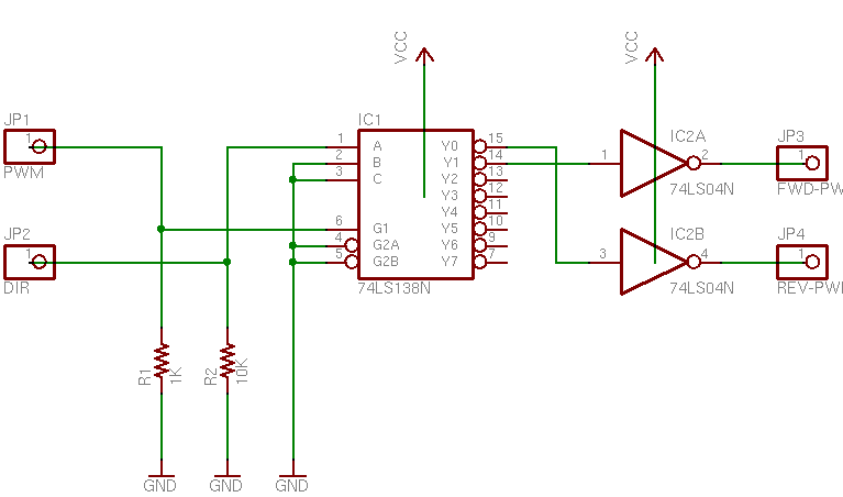
Over the weekend I was working on a bidirectional PWM motor speed control circuit with the LogoChip, and I ended up using a 74LS138 demultiplexer to route the PWM signal to the appropriate H-bridge input. (It’s what I had on hand.) Because I wasn’t that familiar with the ’138, I wanted to test it carefully before connecting it to the motor driver. I needed a logic probe, and I didn’t have one.

A logic probe is a tester–usually a small, handheld tester–with a probe that you poke into different parts of your circuit. When you touch a logic connection, the probe lights up an LED to indicate whether the connection is at a high or low logic level. Radio Shack used to sell one for about $30, although I think they’ve discontinued it and I can’t find it in their catalog any more.

In principle, it sounds simple–something that could be built with two TTL buffer gates, one inverting and one non. In practice, there’s a snag that has to do with the definition of TTL logic voltages: a voltage below .5 – .8V is considered a low signal, a voltage above 2.0 – 2.7V is considered a high signal, and a voltage in between is undefined. (Output voltage specifications are stricter and input voltage specs more generous, to account for lossy transmission.)

The obvious implementation–feeding the input into a TTL buffer–would always indicate either high or low, because the buffer will always produce a valid output even if the input is in the “dead zone.” But the probe needs to have both LEDs off when it’s not touching anything or touching something that’s not a high or low logic signal (like a tristated connection, something that isn’t digital logic at all, an output that’s broken, two outputs mistakenly wired together, etc.). Ironically, to indicate the state of a digital signal correctly, you have to use analog electronics.

I’ve wanted a logic probe for years, and although at $30 I could certainly afford one, I never felt it was quite worth buying one. After building my own, I’d have to concur with my previous opinion. :-)

Different Designs

I searched online and found several logic probe designs, but wasn’t satisfied with any of them. My dissatisfaction fell into two categories:

  • Several of the circuits reported whether the input voltage was above or below 2.5V. That’s doubly wrong: they never go dark to indicate absence of a valid signal; and if you’re going to make that mistake, make it around 1.6V, the middle of the “dead zone.”
  • Other circuits purported to remain dark when the input was in the TTL dead band, but their schematics were beyond my ability to confirm correct operation. They did things like play tricks with pull-up and pull-down resistors between the probe input and TTL inverter inputs, presumably to try to pull dead-band voltages out of the input range of the buffer. I just wasn’t comfortable with this.

So I designed my own around an LM339 quad comparator chip and some resistors, all from my parts bin.

The Circuit

The key to understanding the circuit is to understand the operation of the LM339. A comparator is an op-amp designed to be used open-loop, to indicate which of two input voltages is higher than the other. The inverting input (labelled -) is subtracted from the non-inverting input (labelled +), and if the resulting voltage is positive, the comparator’s output is high; if the resulting voltage is negative, the comparator’s output is low. That is, if the signal provided to the + input is larger than the one provided to the – input, it indicates high; if the signal provided to the – input is larger, it indicates low. In effect, it compares the two voltages.

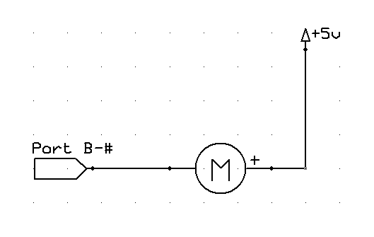
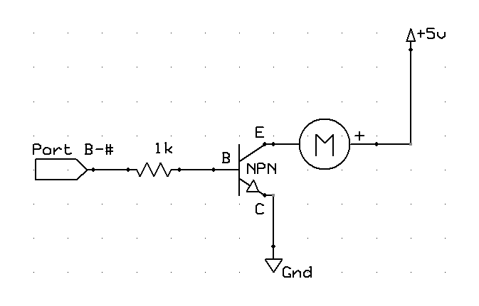
Then keep in mind a small trick: Most transistor and IC outputs can sink more current than they source, so I wanted to wire the indicator LEDs from +5V to the comparator output, rather than from the comparator to ground. That means I had to use inverted logic on the outputs, which is accomplished by swapping the inputs. It’s easily done; it just messes with the brain a bit.

Logic Probe Schematic

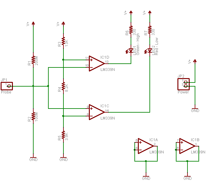
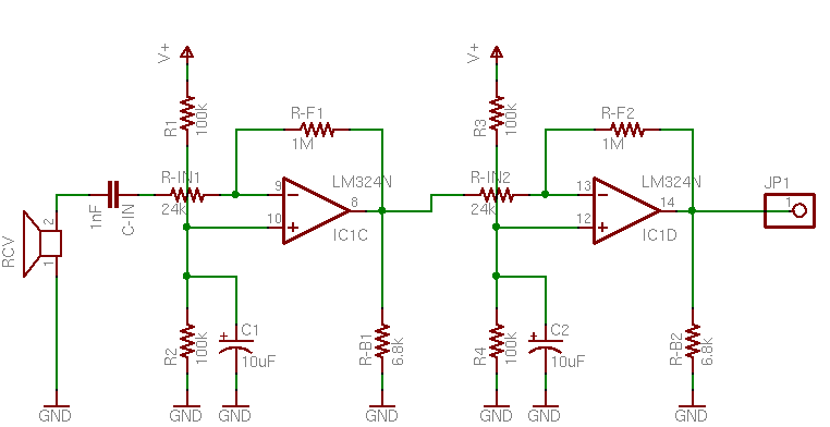
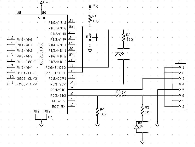
Going through the schematic from left to right, the signal under test is received at the probe input. It’s attached to a high-impedance voltage divider to bias the circuit into the TTL dead band (1.67V) when the probe isn’t touching anything or is touching a high-impedance connection, but which is easily overridden (the bias current is only a few microamps) when a real signal is present.

I built a voltage divider to provide the reference voltages for the TTL low and high voltage levels. I was aiming for .8V and 2.4V; common resistor values of 3.9kΩ, 8.2kΩ, and 13kΩ gave me actual voltages of .78V and 2.41V. Close enough for jazz.

Looking first at the logic-low indicator (which is the lower section on the schematic), the input signal feeds to the non-inverting (+) input of the comparator, with the low reference voltage (.8V from the divider) feeding the inverting input. That means the reference voltage is subtracted from the input voltage, so when the input signal is higher than .8V, the comparator output is high–which leaves the red LED off. (Inverted outputs, remember?) When the input is lower than .8V, the comparator output is low, and the red LED lights.

In contrast, in the logic-high section of the circuit (the upper part of the schematic), the input signal feeds the inverting input of the comparator and the high reference voltage (2.4V) feeds its inverting input. Here the input is subtracted from the reference voltage, so when the input signal is higher than 2.4V, the comparator output is low, lighting the green LED. When the input is lower than 2.4V, the comparator output is high, and the green LED stays off.

The rest of the schematic is housekeeping. Because the LM339 runs as an “infinite-gain” amplifier in an open-loop configuration, it’s subject to self-oscillation, and the datasheet recommends wiring all unused inputs and outputs to ground. And the probe takes its power (and reference VCC) from the circuit under test, so it needs wires to connect to +5V and ground–the jumper at the far right.

Success!

It works like a charm! Because of the inverted logic on the LED-driving outputs, I confused myself about the placements of the inputs a couple of times. But after straightening that out, I haven’t had any problems. It correctly identifies logic levels (and un-identifies non-logic signals), and proved invaluable while troubleshooting my 74LS138 PWM circuit (which will be the subject of another post).

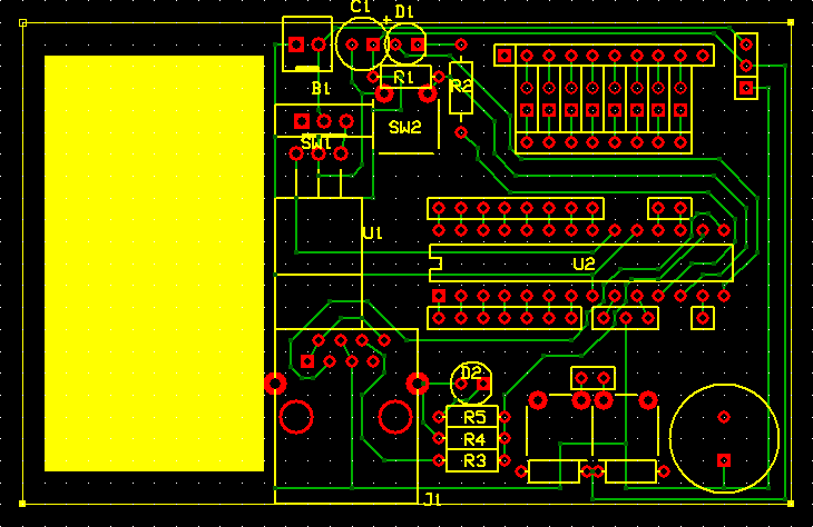
Right now, the probe is built into the rightmost end of the breadboard with my LogoChip, 74LS138, and 74LS04. I’m planning to drill and etch a few dedicated PCBs to make logic probes for myself and some friends, and I’ve just learned to use the Eagle circuit design software–which runs on Mac OS X (among others–another ‘nother post?). W00T!

What’s Missing?

Commerical logic probes have two things that mine doesn’t (not counting a fancy case and a higher price tag): audible output and pulse stretching.
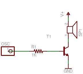
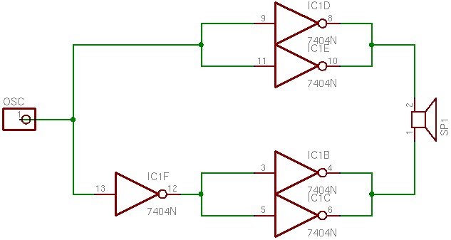
Audible output

Audible output is just what it, er, sounds like: high/low tones played through a little speaker (in conjunction with the LEDs), to indicate high/low logic signals. I don’t think it’d be a big gain for me, but a friend who has one says it’s really handy to be able to focus on keeping the probe tip from slipping off the pin you’re measuring and not have to glance over at the LEDs to check the logic level. I may add that in a future version, or swap probes with him long enough to find out how much it matters to me.

Pulse Stretching

Pulse stretching has to do with the handling of very short pulses. A single bump from low to high of 1ms duration will be detected by the probe and send appropriate current through the high LED, but it’ll probably be so short it can’t be detected (or registered) by the human eye. Pulse-stretching circuitry adds a short-duration timer (say 1/4 second) to the high and low indicators, so that every time a high signal is detected, the indicator lights (and/or sounds) for at least a minimum amount of time (e.g. 1/4 second)–and then for as long as the signal remains at that level. It just gives your eye longer to detect very rapid pulses.

I’m undecided on the topic for my own use, though. I know it’d be annoying to have short pulses coming through and miss them because they were too brief to see. On the other hand, since a lot of what I’m interested in testing right now is PWM signals, I don’t want pulses stretched. PWM is all about repeating rapid pulses, and I prefer to have variable (perceived) LED brightness as an indicator of PWM duty cycle.

I suppose the right answer is to add a switch to select the behavior. Pulse stretching isn’t difficult–it’s just a couple of monostable multivibrators, and the LM339 datasheet shows how I could build them from the two unused gates on the chip I’m already using. That dashes my hopes of dropping from a 14-pin quad comparator to an 8-pin dual comparator and making my logic probe extra slimmy; but sometimes that’s the price you have to pay for greatness.

Voltage Supply

One last consideration is that my circuit “trusts” the voltage supply from the circuit under measurement. The logic probes that I’ve seen all take their power from the test circuit–but mine also divides the circuit’s voltage to get its reference voltages. That means that if the test circuit’s voltage is nonstandard or faulty, my probe will behave differently than expected. It’s unlikely to be damaged–the LM339 can run on a supply voltage of 3-18V–but it wouldn’t necessarily deliver accurate results.

And there’s not much I can do about it without getting a lot fancier–a 7805 regulator needs something like 2.5V of headroom to maintain regulation, and even the more efficient regulators need some headroom. So when the probe is receiving the expected 5V supply, adding a regulator would potentially make it behave worse. I could do something clever stacking diodes to construct a reference voltage, but I’m not sure it’s worth it to me. Guess I might play with it for V2.

LogoChip: PWM Motor Control

Thursday, March 9th, 2006

Built-In PWM

A while back, John sent me some code that he and Tom had been using to test the pulse-width modulation (PWM) capabilities of the hardware underlying the LogoChip. I read through the PIC18F2320 datasheet over the weekend and learned how it does PWM; and between John and Tom’s sample code and the information in the datasheet, tonight I got a motor running at variable speed under software control.

To use the PIC’s PWM, you configure the Timer 2 counter for the modulation frequency (period, actually), then set the output port into PWM mode and configure the duty cycle. Sounds simple; it’s really just a matter of finding all the control registers and the proper bits. Because the PWM is implemented in the chip’s hardware, it keeps running at the last-set duty cycle (== motor speed) even if you’re doing something else or your program stops running, so you can set and forget.

I’d like to measure the PWM output frequency and confirm what the Timer 2 counter and prescalar are doing, but my frequency counter is giving me weird results and I have no idea how far out of calibration my scope is, so that’ll have to wait for another day. When I hook a speaker to the output, it sounds well below 440Hz, but the frequency counter is trying to tell me it’s 2+kHz. Feh.

Huh, when I calculate the frequency (if I’m doing it right), I come up with ~2.4kHz. My speaker is a piezo and it sounded funny, so maybe that’s outside its range and the frequency counter was right on?

The Code

After I got over the excitement of just getting it to work at all, I wanted it to do more than let me manually set a speed for my motor, so there are a couple of extra procedures at the bottom (pwm-speedup and pwm-slowdown) to ramp the speed from slow to fast and back down to slow. They add to the code length, but they’re not critical for implementing PWM.

Here’s the program:

Here’s the code:

;   Keith Neufeld
;   08-Mar-2006
;
;   LogoChip program to demo motor speed control with PIC PWM output.
;   Uses PWM channel 1 on port C2.  Duty cycle values determined with
;   NPN transistor driver with 9V motor supply.

constants [
    [CCP1CON $fbd]                      ;   capture/compare/PWM 1 control reg
    [T2CON $fca]                        ;   timer 2 control register
        [TMR2ON 2]                              ;   timer 2 enable bit
        [T2CKPS1 1]                             ;   timer 2 prescale bit 1
    [CCPR1L $fbe]                       ;   C/C/P 1 register low byte
    [PR2 $fcb]                          ;   timer 2 period register

    [pwm-port-ddr portc-ddr]            ;   PWM 1 outputs on port C2
    [pwm-bit 2]

    [period 255]                        ;   default timer period to use
    ;[low-duty 110]                     ;   lowest duty cycle for my motor to
    [low-duty 10]                       ;   start from a stop
    [high-duty 255]                     ;   highest possible cycle
]

;   Initialize PWM by configuring timer 2 for PWM period and enabling PWM mode.
to pwm-init
    clearbit pwm-bit pwm-port-ddr       ;   set PWM port to output

    ;write T2CON 6                      ;   set timer 2 on, prescalar 16
    setbit T2CKPS1 T2CON                ;   set timer 2 prescalar to 16
    write PR2 period                    ;   set timer period highest possible
    setbit TMR2ON T2CON                 ;   turn on timer 2

    write CCP1CON 12                    ;   set PWM mode
    ;write CCPR1L 128                   ;   set 50% duty cycle
end

;   Set PWM period and duty cycle.
to pwm-set :period :duty
    write PR2 :period                   ;   set timer period
    write CCPR1L :duty                  ;   set PWM duty cycle
end

;   Disable PWM by shutting off timer 2.
to pwm-off
    pwm-set 0 0                         ;   disable PWM by setting duty cyc to 0
    clearbit TMR2ON T2CON               ;   and turn off timer 2
end

;   Enable PWM and ramp up to highest speed at :increment / 255ths
;   per 1/10 second.
global [duty]
to pwm-speedup :increment
    setduty low-duty
    pwm-set period duty
    repeat ((high-duty - low-duty) / :increment) [
        wait 1
        setduty duty + :increment
        pwm-set period duty
    ]
    setduty high-duty
end

;   Enable PWM and ramp down from highest speed at :increment / 255ths
;   per 1/10 second.
to pwm-slowdown :increment
    setduty high-duty
    pwm-set period duty
    repeat ((high-duty - low-duty) / :increment) [
        wait 1
        setduty duty - :increment
        pwm-set period duty
    ]
    setduty low-duty
end

LogoChip: Small Motor Control

Wednesday, March 8th, 2006

LogoChip Motor Control

Yesterday after class, Steve Atwood and John were talking about controlling a small motor from one of the LogoChip’s output ports. Steve had wired the motor from the LogoChip to ground, and when he activated the output port, the motor would barely spin.

The problem is that the chip on which the LogoChip is based can’t source a lot of current, so it can’t provide enough power to run the motor (even a small one). There are a couple of other ways to wire the motor that work better (which I’ll show below), but first, let me try to explain why it doesn’t work when it’s wired the simple way.

Source and Sink

Imagine a T-fitting attached to a faucet, with the bottom draining into the sink and the side leg connected to a hose. (This is almost exactly like the faucet fitting on a roll-up dishwasher, except the dishwasher has two hoses and we have only one.)

The T-fitting has a valve in it that you can turn, which connects the hose to either the faucet or the sink. So if you turn the valve to the faucet position, you can supply (“source”) water to the hose; if you turn the valve to the other position, you can put water in the other end of the hose and have it drain out into the sink.

One last complication: You only open the faucet enough to supply a trickle of water, not a torrent. But the bathtub is nearby, and you can open its faucet all the way to get as much water as you want.

If you wanted to use the water to spin a water wheel, what would you do? Your first instinct would be to set the valve so that the faucet supplies water to the hose, and hold the hose over your water wheel. That would work–sort of. Because the faucet will only supply a trickle of water, you only get a trickle into your wheel, and it doesn’t turn very fast.

Although it’s counterintuitive, you can actually spin the wheel faster by running a hose from the bathtub faucet (open wide) to your water wheel, then holding that over a funnel into the hose to your sink, with the valve (remember the valve?) set to drain water from the hose into the sink. The bathtub supplies all the water you want, the wheel spins, and the valve drains water down the sink as fast as the bathtub supplies it.

That’s a reasonable parallel for how the circuitry works on the output pins of our LogoChips. They’re not able to source a large amount of current (a trickle of water from the faucet), but they can sink quite a bit (sending the bathtub’s water down the drain).

Active High

Last night, I tested controlling a small motor in three different ways from my LogoChip. First, I hooked it directly to the LogoChip pin and to ground, so that when the pin was on, the motor ran. This type of arrangement is called “active high,” because when you want the motor to be active, you make the voltage on the chip’s pin high.

Motor Driven from PIC Port, Active High

To turn on the motor, I set the port’s value to 1 (setbit). This made the port output +5V, causing power to flow from the pin through the motor to ground. (Engineers, pardon me for using positive current flow, but there’s no point in getting into that much detail in this class.) The motor spun, but weakly.

Active Low

Next, I tried a configuration called “active low,” in which you set the chip’s pin to a low voltage to make the motor active. To set this up, I wired the motor from the pin to the +5V power connection, instead of to ground.

Motor Driven from PIC Port, Active Low

Then to activate the motor, I set the port’s value to 0 (clearbit), so that the pin’s voltage dropped to 0 and power was coming from +5V through the motor to the pin. The motor spun much faster, demonstrating that the chip is able to sink more power than it can source.

Transistor Driver

Finally, I tested using a separate transistor to power the motor. I had a suspicion that even though the motor ran faster in an active-low configuration, I might be able to get yet more performance using a separate transistor.

Motor Driven from PIC Port, NPN Transistor Driver

In this circuit, the LogoChip port goes high (+5V) and sends a small current (5mA) through the base-collector (B-C) junction of the NPN transistor. The transistor has a beta (amplification factor) of about 200, so that permits an emitter-collector current (E-C) of about 1A–enough that I’m pretty sure the transistor is in saturation, even though I haven’t checked the datasheet.

In non-geeky-electronics terminology, the transistor is working like a relay. A small amount of power through the relay coil controls a large amount of power through the relay’s contacts. In the case of the transistor, one wire (the collector) is shared between the low-power coil circuit and the high-power contact circuit. All the stuff with the numbers is just calculating the right value(s) of resistor(s) to use based on your circuit and the characteristics of your transistor.

And it worked as expected. The motor spun noticeably faster with the transistor driver than it did even in the active high configuration.

Stuff for Steve

I dug a couple of salvaged transistors and resistors out of my parts bins, soldered longer leads onto them, and brought them to work today for Steve to try out. I’ll be interested to see how much difference it makes for his motor. And like Tom McGuire, I have plenty of stuff saved up, so the offer’s open to anyone in class if you need help with circuits or components.