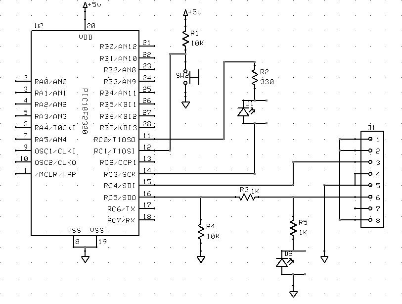
I’ve been looking for circuit design and PCB layout software for a long time, and in the past couple of weeks I’ve settled on EAGLE. I’ve used it to draw up the most recent schematics here on my blog. Its key advantages for me are:
- There’s a freeware version. I don’t do enough circuit design to justify paying a lot of money for commercial software–especially software that I haven’t got to try first.
- It can output netlists from it circuit design module to use with other PCB layout software, and it can output Excellon drill files to use on my friend Joel’s CNC drilling machine.
- It runs on Windows, Mac, and Linux–and I expect to use all three versions regularly.
To understand why I like it so much, though, it’s worth running through the other software I’ve used.
Electronics Workbench: Multisim and Ultiboard
I got a student copy of Multisim and Ultiboard with my electronics textbooks in 2004. I used it a lot in class, and I think it’s fantastic for doing circuit simulation. It blows me away that it’s even possible to do that level of analysis and simulation on a commodity PC, and I really appreciate Multisim for what it does.
Unfortunately, I also had a not insubstantial list of complaints:
- The Multisim (circuit design/analysis) UI is pretty glitchy. I had a lot of trouble selecting the component I wanted to move; I’d box-select a group of components and drag them, and parts would get left behind (and disconnected); etc.
- I had trouble getting the hang of the UI for Ultiboard, the board layout software. I don’t remember exactly what I didn’t like, but I know I gave up in frustration pretty quickly.
- Worst, though, is that the installation uses a nodelocked license. I installed the software on two PCs in Pittsburg, and when I left, I completely uninstalled it. I’m now within the rights of my license to install it on another PC–but I’ll have to call EWB to get another install code, because I’ve installed it too many times to get a new code automatically.
So I feel like the next time I install it, I need to be ready to put it onto one PC where I’m going to leave it forever–because how many more times can I call them and tell them (truthfully, but they have no way of knowing that) that I’m moving it to yet a different PC? The offshoot of that is that I’ll probably never install it again.
PCB123
I had used ExpressPCB (next) a long time ago, and while I was searching for it recently, accidentally installed PCB123 instead. Like ExpressPCB, PCB123 is a company that makes small quantities of PCBs for prototyping and hobbyist use, and gives away the software to design the circuit and layout the boards. I don’t even remember what I didn’t like about PCB123–I just know that it took me about five minutes to realize it wasn’t ExpressPCB and I wasn’t willing to learn to use it.
ExpressPCB
I had been happy with ExpressPCB for a long time. They’re a board manufacturing house, and they figured out long ago that if they give away circuit design and board layout software, they’ll entice people to use their services.
I think they walk a delicate line trying to decide how much functionality and interoperability to put into their software–too much and people might use their software and then have boards manufactured elsewhere; too little and people will get frustrated using their tools.
In my case, despite finding their UI to be the absolute best I’ve handled, the functionality is too low, and I’ve moved away from their software. With a little more functionality, I’d still be using their software, and I’d turn straight to them when I need a board commercially produce.
First, I have to sing their praises:
- I found the UI to be fantastic, in both the circuit design and board layout sections. The toughest operation for this type of software seems to be selecting an existing part to move, and I would almost always get exactly the part I was trying to select; it was easy to reselect a different part in the cases when I didn’t get it on the first try.
- Their board layout software has a netlist checker, so you can see which pins need to be connected. (However, see “ratlines” below.)
- The UI just has a good “feel” to it–everything handles very nicely.
However, its drawbacks were serious enough for me to move away from it:
- Foremost, because the software exists entirely to get you to buy boards from ExpressPCB, it has no facility for exporting drill files. I’m drilling boards on my friend’s machine, drawing traces by hand, and etching in a plastic tank–I pose no threat to ExpressPCB’s business–but I can’t use their software to automate my homebrew process. It can’t be made to meet my needs.
- ExpressPCB doesn’t prepopulate the PCB layout with the components used in the schematic. You have to add and label each component individually. That’s time-consuming and error-prone.
- ExpressPCB doesn’t support ratlines indicating netlist connections. Yes, it can highlight solder pads that need to be connected–but it’s easier to lay out traces when you have ratlines indicating all of the connections that need to be made.
- The board layout UI is a little over-eager to merge connections. I’ve had to scroll the entire board off the screen when calling up a new part to add, because with the board on the screen, the part got merged into existing traces before I could even select where the part was to be placed. Similarly, I’ve had entirely unrelated traces merged together because I was dragging a set of parts to a different area of the board, and corners of traces I was dragging (and would have rerouted as the next step) landed on top of other traces.
The biggest issue, of course, was being able to produce the interchange formats I needed–but the other issues served as cautions while looking at other packages.
FreePCB
FreePCB is a really nice-looking package, an amazing programming accomplishment from a single individual, and free of cost but not open source. I like it a lot, and I expect to use it for larger boards in the future. It’ll import component and netlists from other software, and it’s what led me to EAGLE for circuit design.
A few observations:
- It doesn’t have any corresponding circuit design software. That’s means there’s no way to automate back-annotation when changing a design during PCB layout, and the coupling for forward updates isn’t as tight as with some of the other packages.
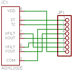
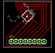
- It’s extremely tedious to lay out a board from scratch without an accompanying parts list from a circuit design package. FreePCB is intended to be used in conjunction with circuit design software, and I’d want to use it that way most of the time. However, I was trying to lay out a one-component, two-connector board without having drawn the schematic, and found it prohibitively difficult to do.
- It has ratlines, a nice feel, decent export capabilities, etc. It was designed by an engineer–it was made to work well.
EAGLE is a little smoother for me to use, but the free version has some restrictions that I may eventually run into. When I do, I plan to use FreePCB for those boards.
Hand-Created Drill Files
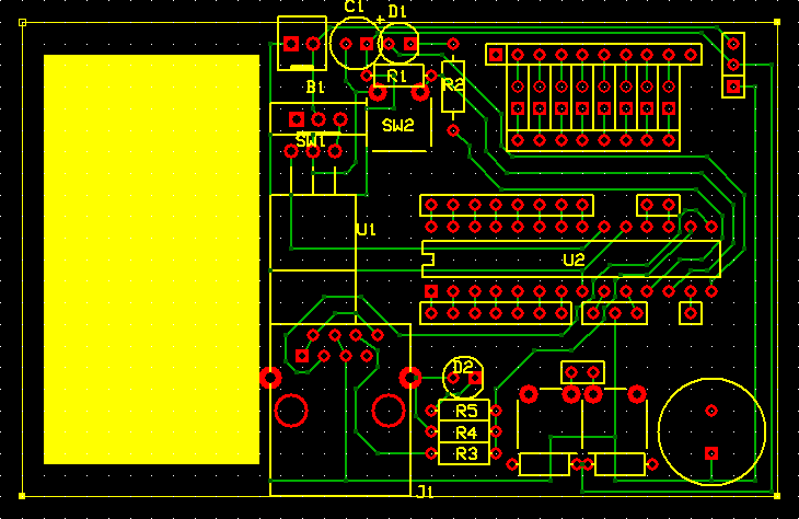
For a 2″ x 2.5″ board with a PIC microcontroller, RJ-45 connector, LED array, lots of sockets, and supporting passives; for the one-component board I mentioned above; and for a couple of other boards I’ve worked on since then; I’ve drawn the circuit (and sometimes the PCB) in one package or another, and then laid out the drill file by hand. It’s not hard–key in a zillion (x,y) coordinates, plot the file in gnuplot to make sure it looks right, use a small Perl script to translate to rudimentary Excellon code, and drill it.
It’s a dumb way to have to do things, but it got me a drill file that I couldn’t get out of ExpressPCB, and it got me a layout that I didn’t have time to figure out how to do in FreePCB. I’d rather not make a lifestyle of it, though.
EAGLE
Which brings me to EAGLE, the software I think I’m going to be using for a long time to come. It outputs the formats I need, it runs on all the OS platforms I use, and a slightly restricted version is available at no cost. The freeware limitations won’t impact me for quite a while: only one-sheet schematics, only two-layer PCBs, and PCBs no larger than 4″ x 3.2″. I’ll hit the last one first, and I’ll use FreePCB for layout when it happens.
I do have a few complaints about the UI:
- It’s often very difficult to select an onscreen part to move to a different location. I’m starting to resort to drawing a select box around the interior of the part in order to select it and nothing else; I much prefer the click-click-click to cycle through overlapping parts. I think there’s a right-mouse trick to cycle in EAGLE, and I need to learn it.
- Speaking of right-mouse, too much of EAGLE’s functionality depends on it. I use the right mouse button nonstop when I have one, but my PowerBook doesn’t.
- The screen doesn’t automatically refresh objects when other objects have been covering them and are removed, at least not in the X11 versions. Yes, I can hit F2 to redraw the screen, but it’s often really messed up until then.
- EAGLE seems to have serious problems performing unintended merges during component rotation operations–I have PCB traces that get stuck together and I have to reroute by hand. Worse, that situation seems to corrupt the netlist, because it changes the ratlines. I’m stuck with leftover ratlines that disagree with their traces, and no way to correct them. This is very problematic.
But mostly gratitude at finally finding software that does so many things right:
- Pretty good coupling between the schematic and board layout sections, including prepopulating components and ratlines
- The ability to export a netlist to use in a separate board layout program
- The ability to export drill files in Excellon format to drill my own holes
Have you tried WinQCAD? It has a great autorouter, produces Gerber files, and is easy to use. There’s a free version available.
Dear sir,
i would like to know, if i have a circuit diagram designed on the eagle software.. how do i test if it works if its implemented? would be really happy if u can reply me the answer… thanks alot
Ruben, are you asking for a circuit emulator? EAGLE doesn’t provide that; it’s only a schematic and board layout drawing program. Look for something like Multisim or a variant of SPICE if you want to do emulation.
Of course, another answer is to breadboard the circuit before you draw it, and build a prototype board afterward to see whether you drew it right . . .
To date I’ve laid out 10-20 boards using ExpressPcb. I also like their software, but am now looking at board manufacture and assembly requiring Gerber files. So I’,m looking for something else that’s not too pricey.
I really like the ExpressPcb netlist schematic-to-board checker. Using this tool I never had an electrically incorrect board.
Do programs such as Eagle have this type of netlist check function. If not, what do they do to ensure your schematic compares electrically with the pcb?
Thanks,
Kip
Kip, ExpressPCB has probably progressed quite a bit in over two years since I tried it. So I’ll try to explain EAGLE in a way that makes sense for what I used to know of ExpressPCB; and forgive me if things are different now.
When I used ExpressPCB, you had to add the parts to the board yourself. EAGLE (and other, more-expensive, professional design programs) automatically build a schematic and a board at the same time. You have two windows open; and when you add a part to the schematic, it automatically adds it (off to the side) to the board as well.
Related, EAGLE (and other software) uses “ratlines” on the circuit board to indicate connections that exist on the schematic but still need to be routed on the board. Again, as soon as you add a connection on the schematic, EAGLE adds a ratline on the PCB directly from endpoint to endpoint, kind of a like a rubber band that’s connected to the two ends and will stretch a straight line from one to the other as you move them around..
You select the “routing” tool and click on a ratline you want to turn into a trace, and you can start clicking point to point to route it. You can leave off mid-way through and the ratline runs from the end of your routed section to wherever it’s supposed to go.
Also, automatically after certain operations and manually on demand, EAGLE will recalculate ratlines and move them to the shortest path between two nets. So it won’t always be your preferred path; but it’s pretty handy that you’re visually seeing a preview of the shortest set of connections that would get the job done.
Finally, EAGLE does have design and error check tools that will guarantee that the PCB matches the circuit, doesn’t have any yet-to-be-routed traces, and meets certain design rules such as minimum distance between traces, traces to pads, traces and pads to the edge of the PCB, etc.
I think that addresses everything you were asking; but if you have more questions, I’ll be happy to give them a shot.
Keith…it is now Jan 2010 and you are still up-to-date. I’ve been using Express PCB daily and you still need to add every part to the PCB after you’ve drawn the scematic and there is still no ratnest…. only highlighted pads as you route.
Does anybody know if there prices for board fabrication are competative?
Just wondering if Eagle does circuit simulation