Archive for March, 2011

MakerBot CupCake: Print from the SD Card

Sunday, March 27th, 2011

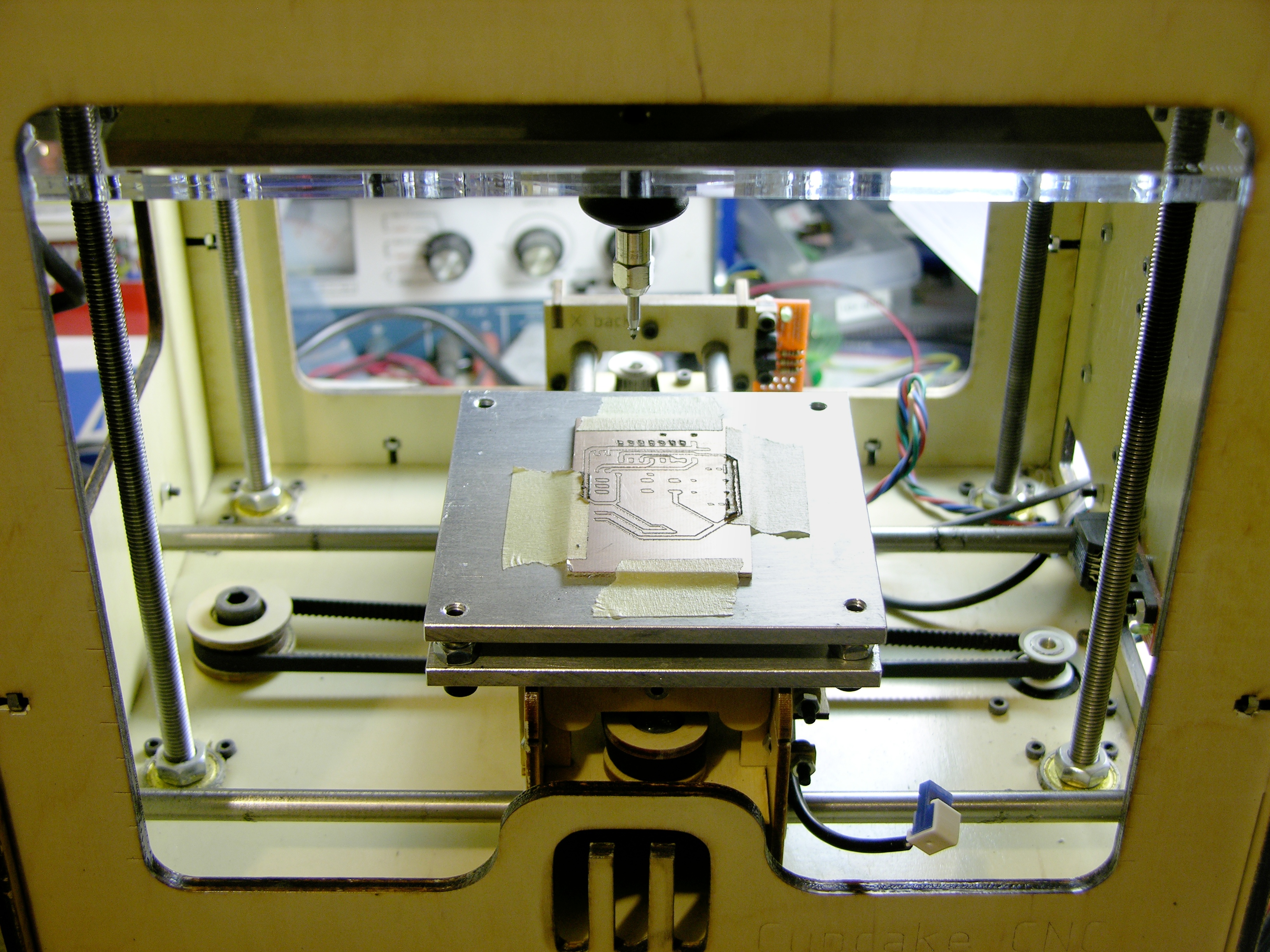
The CupCake plastic-extruding 3D printer can have its printing instructions sent to it live from the controlling computer or stored onboard on a mini-SD card and printed from there. We’ve all seen suggestions to print from the card for improved print quality, but it didn’t make sense to me that USB communications were slow enough (bandwidth) or unpredictable enough (jitter) to make a difference. How wrong, how wrong I was.

Wade idler block printed on MakerBot CupCake with default settings

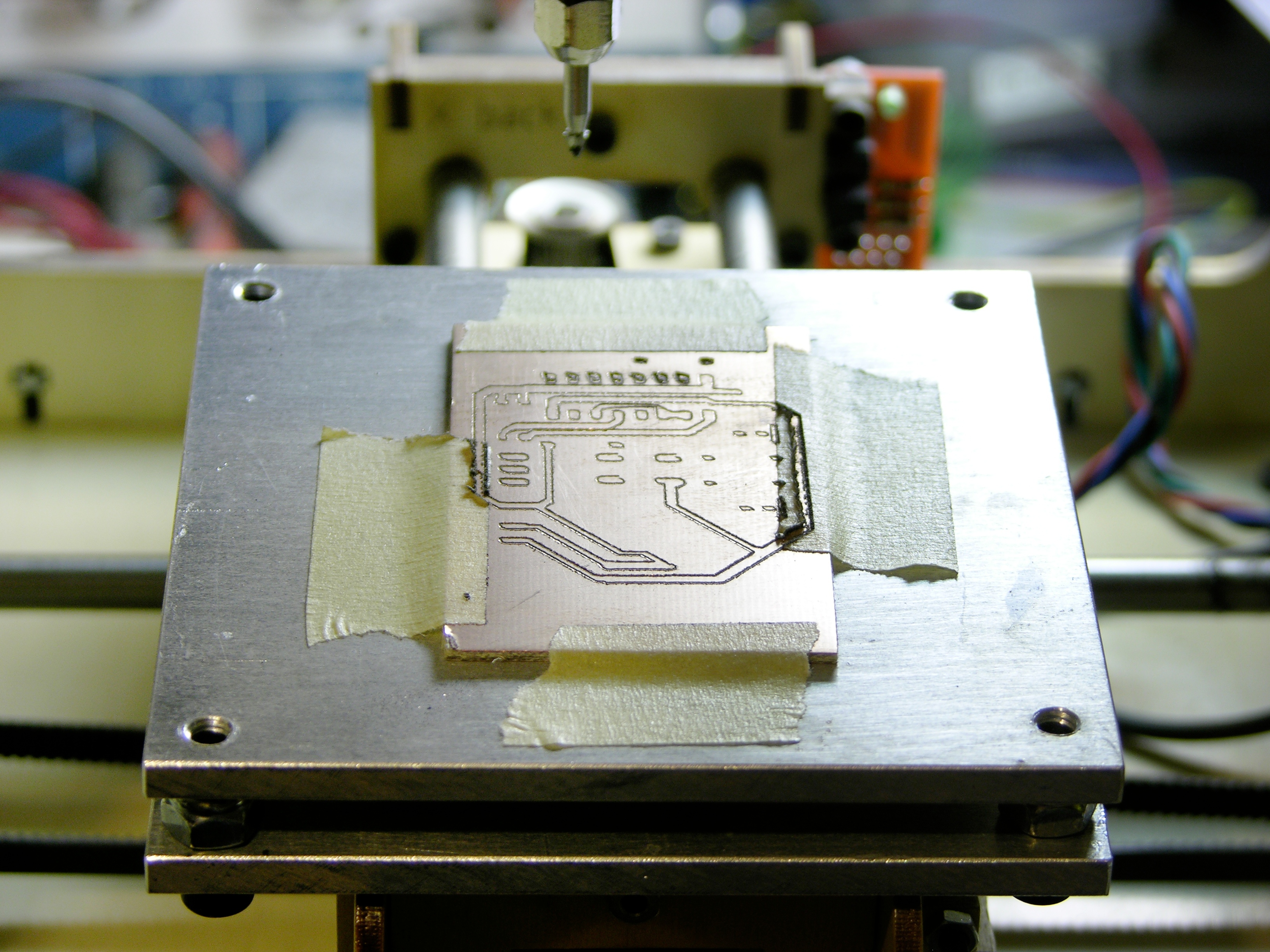
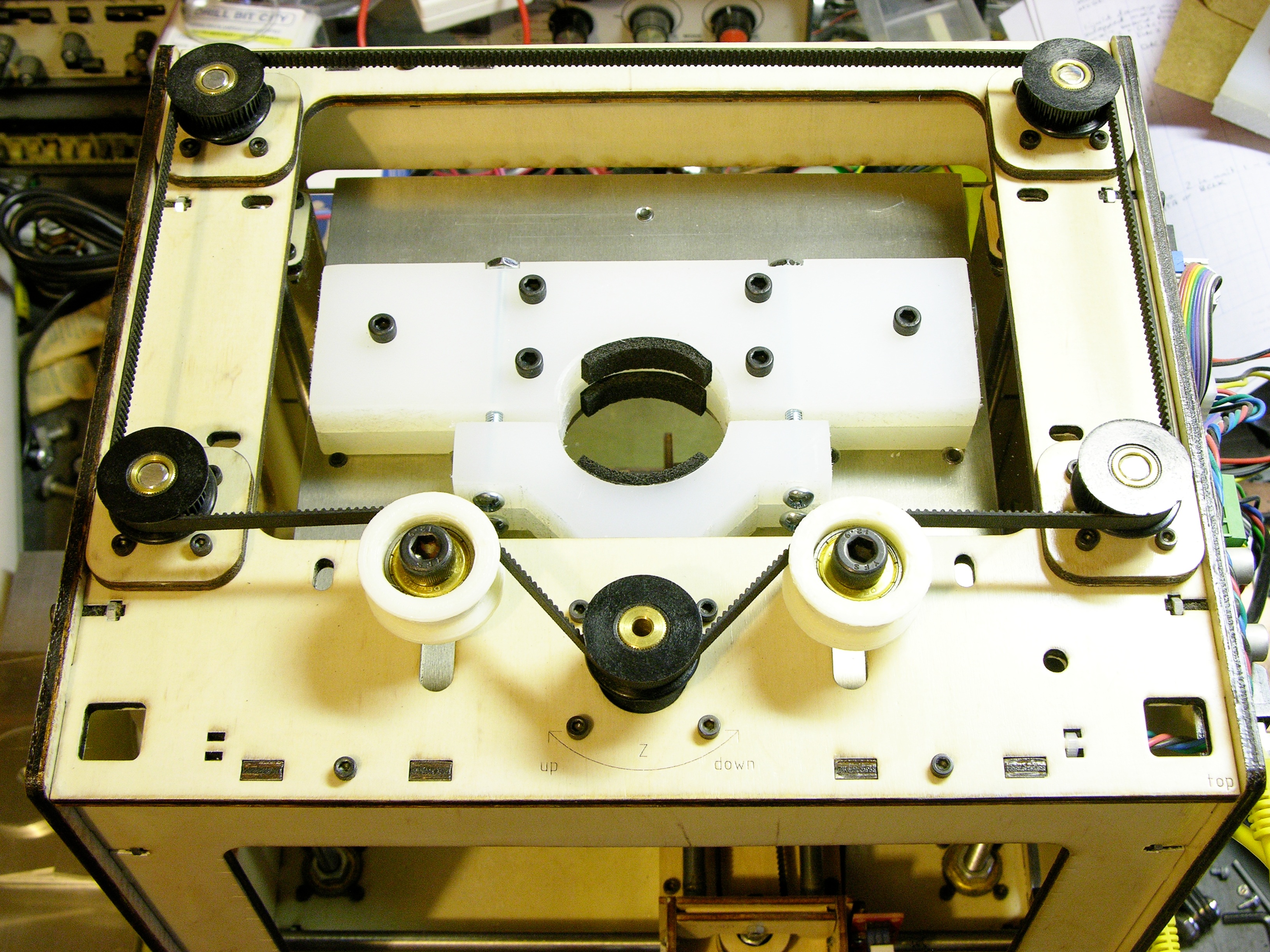
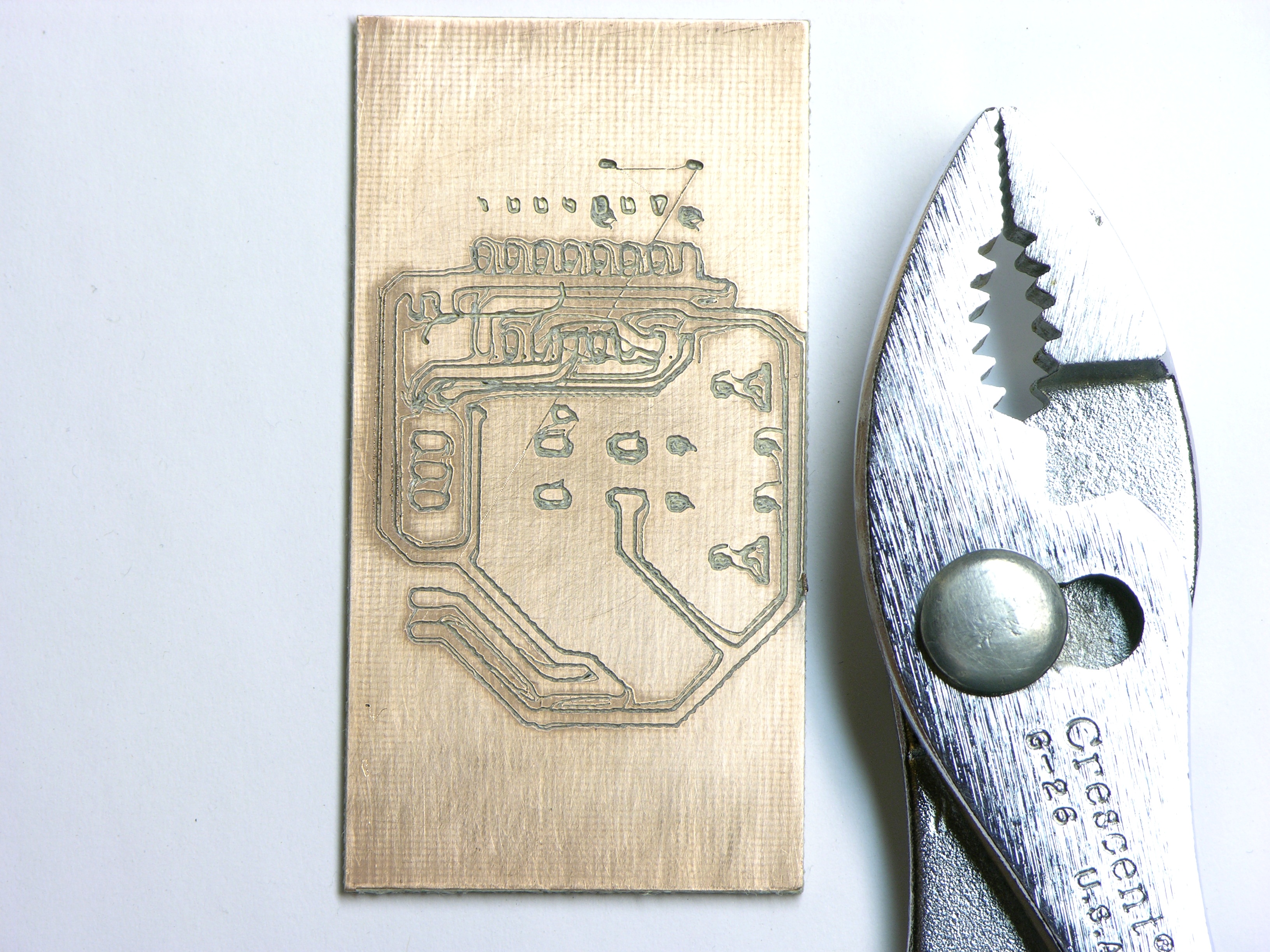
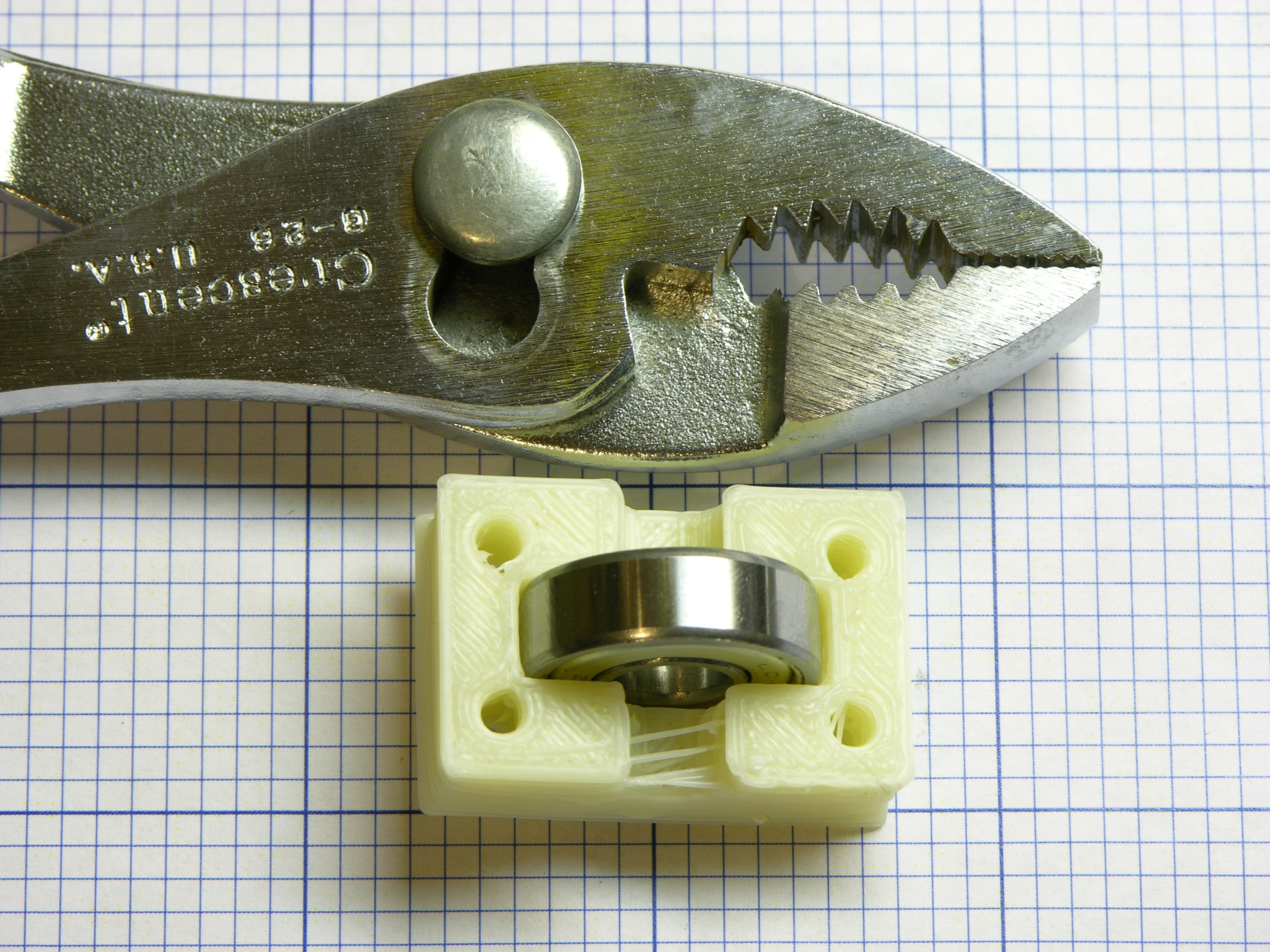
I’m intending to print several different versions of the Wade filament drive to test and upgrade my Plastruder MK3, starting with Wade’s original. In the model of the idler block, each corner has a mounting bolt hole all the way through; but the CupCake slows down so much while circling the holes (without the filament drive slowing down at all, thereby depositing extra plastic) that halfway through the holes were closed over and by the end they were blobbed up above the deposition plane. Besides making an unusable object, this snags the extruder nozzle every time the mound comes by.

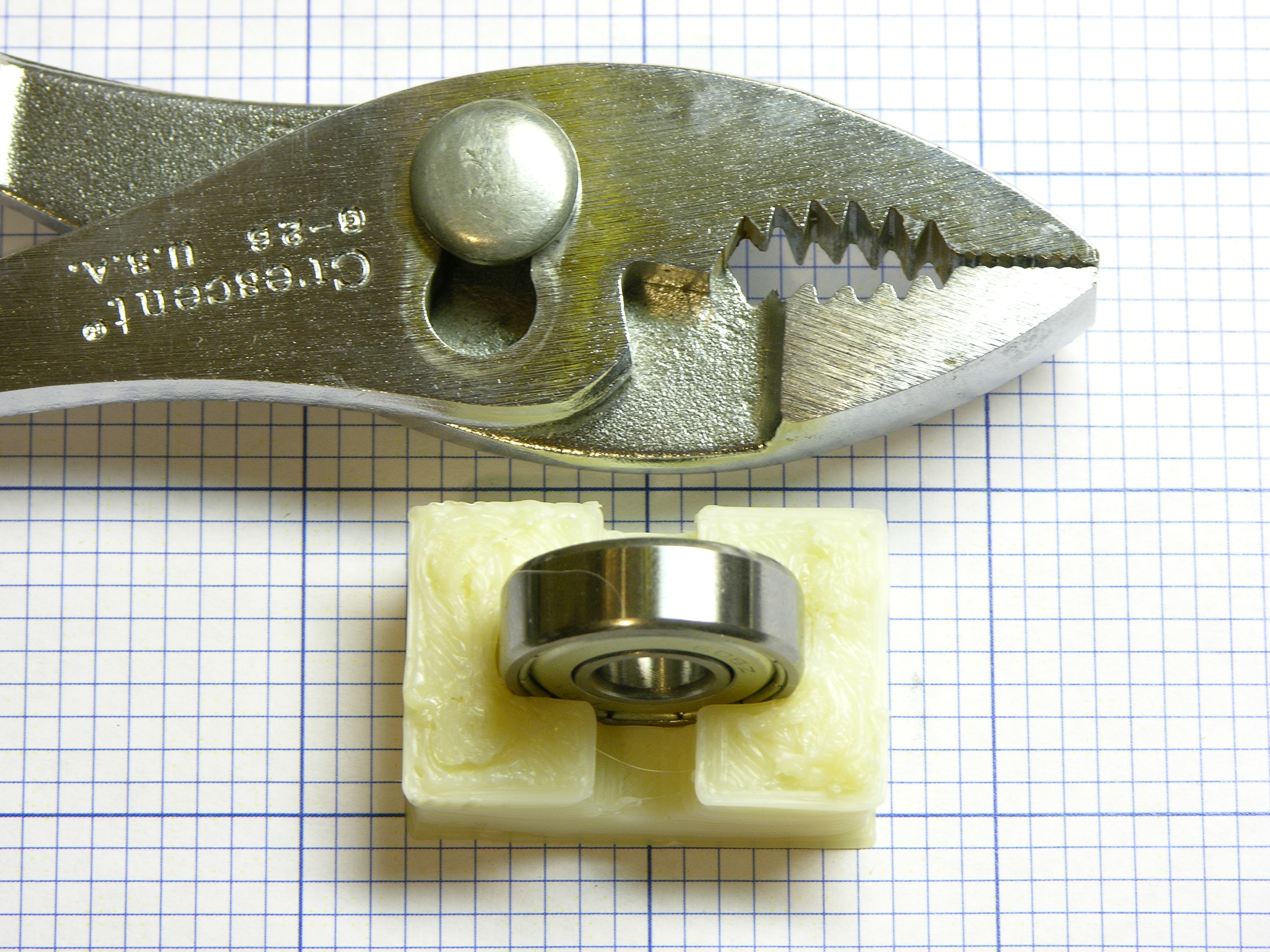
The bearing is supposed to spin freely in the slot and I couldn’t press it all the way in.

Wade idler block printed on MakerBot CupCake with Unpause

I’ve had tremendous luck with Skeinforge’s Unpause module before, which is supposed to mitigate the time the CupCake’s relatively slow Arduino CPU needs to calculate the toolpath for every segment of a curve, but here it didn’t help a bit. Circling the holes seemed just as slow and the result was almost identical.

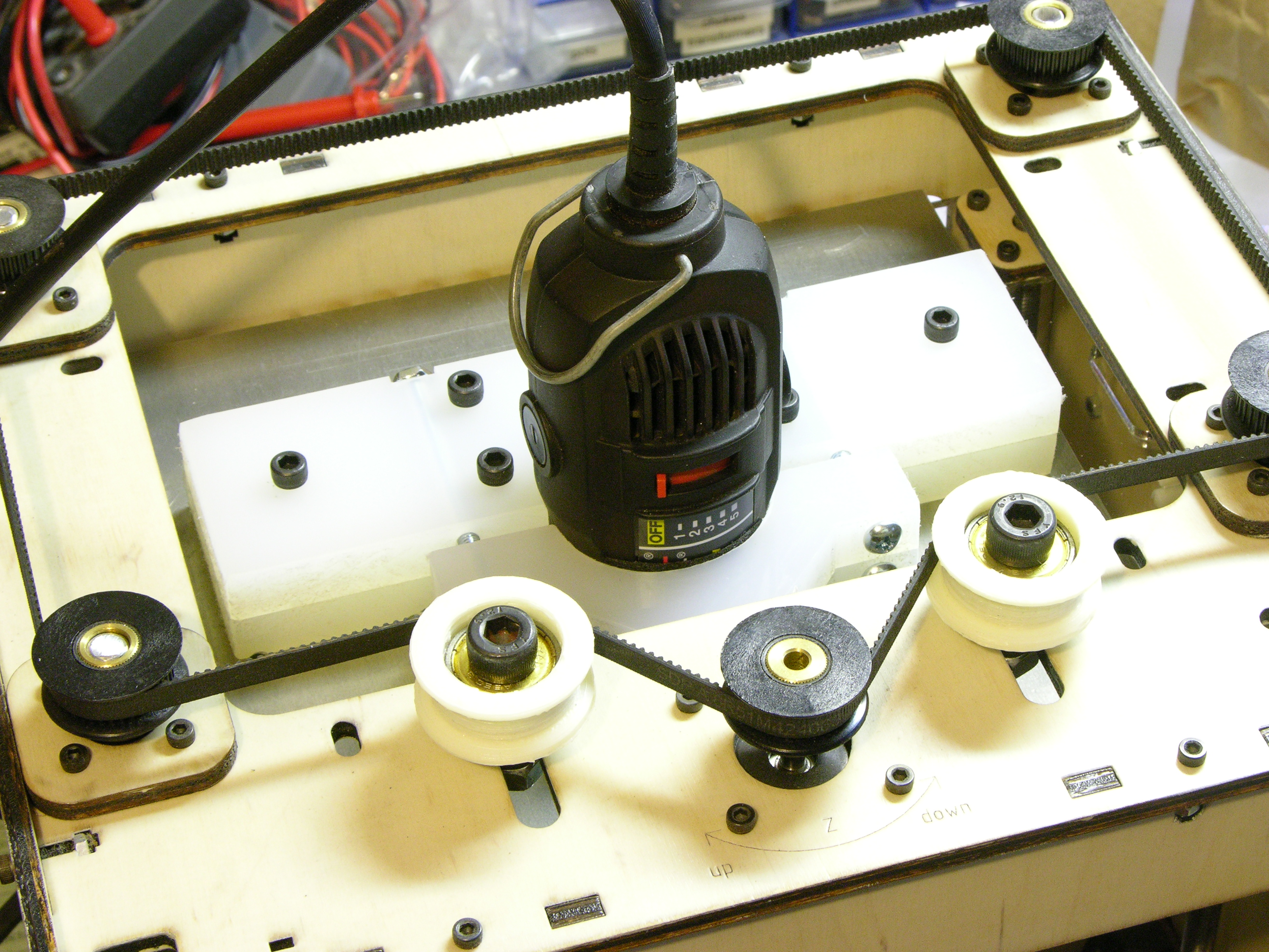
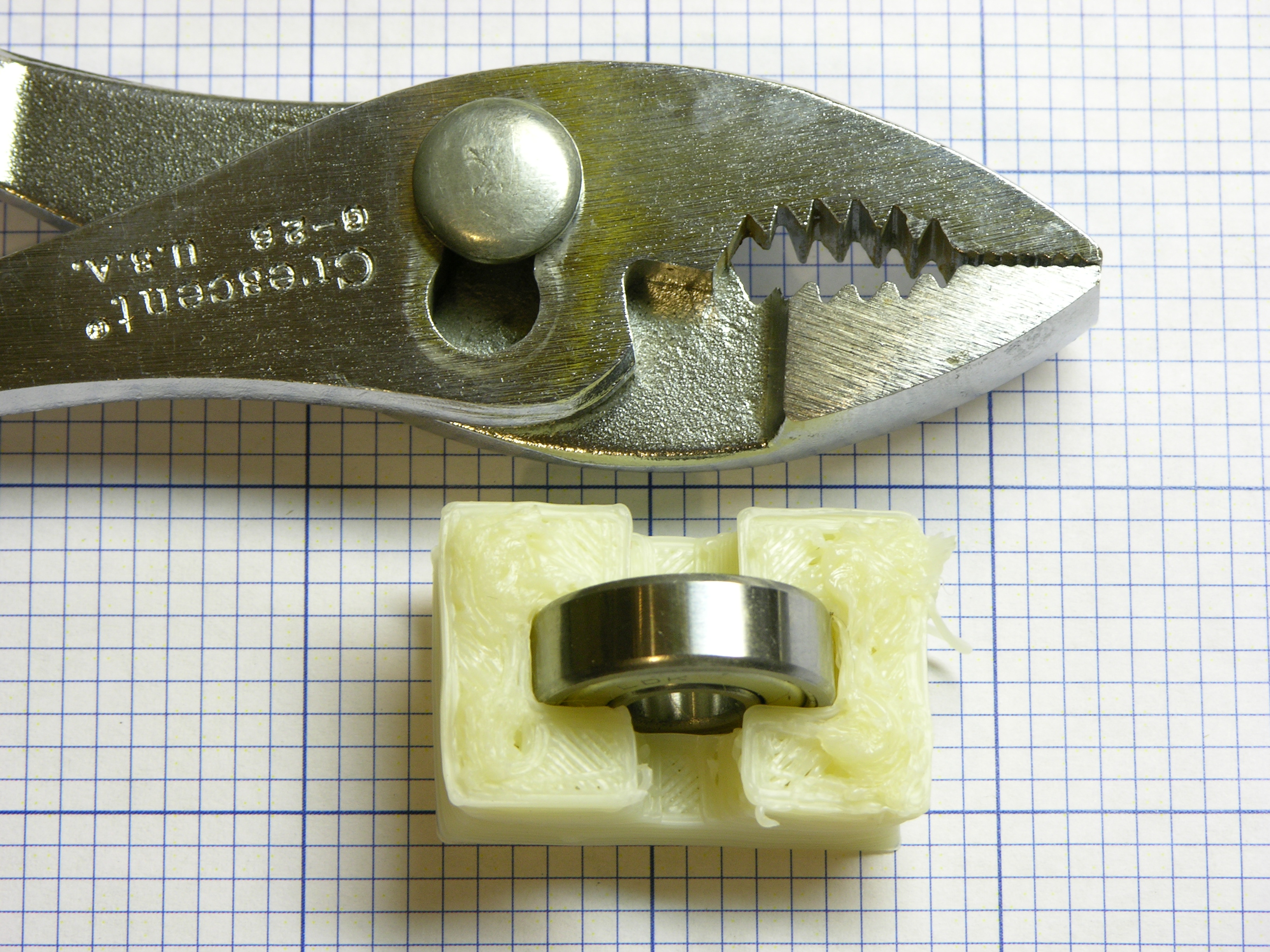
I was able to press the bearing all the way in, but it was a tight fit.

Wade idler block printed on MakerBot CupCake with Stretch

The Stretch module widens curves and corners to take into account the inner edge of the filament following a smaller-radius path than the center. It looked promising on the first couple of layers, but soon I had so much blobbing that the Y-axis stepper lost steps.

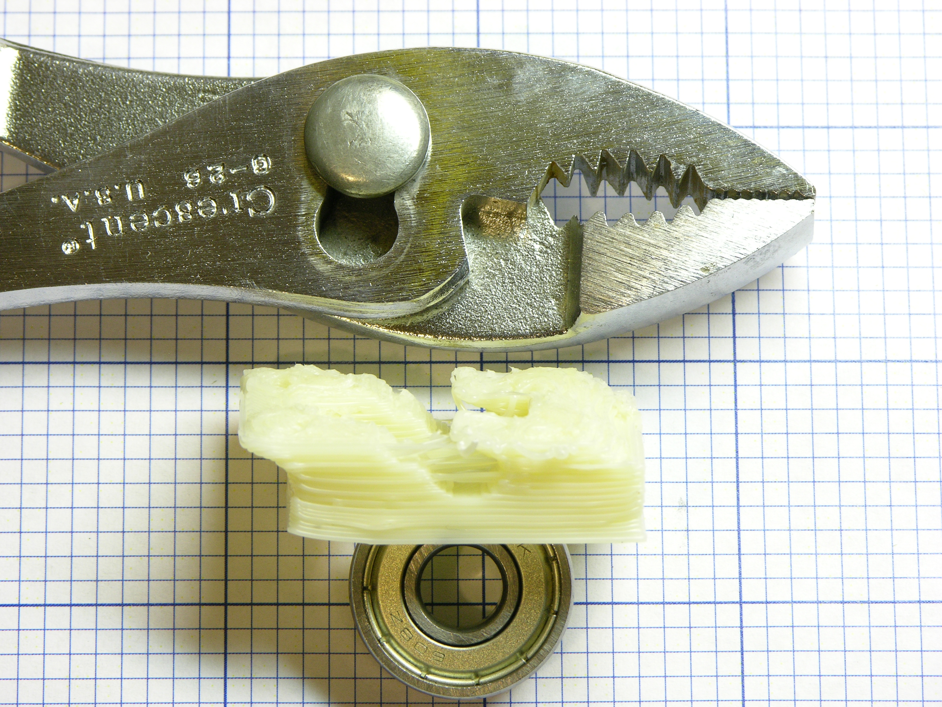
The bearing fit easily into the intact underside of the slot.

Wade idler block printed on MakerBot CupCake with default settings from an SD card

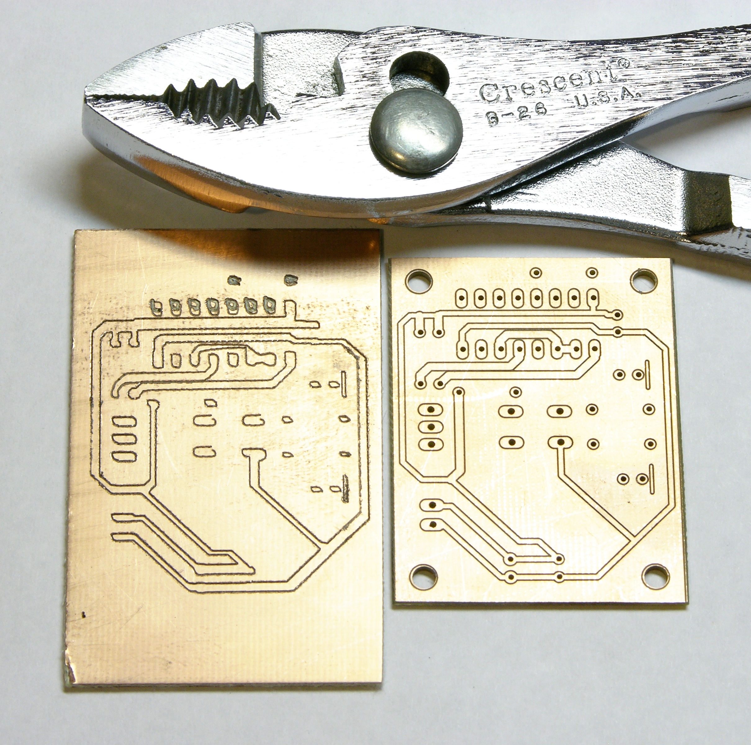
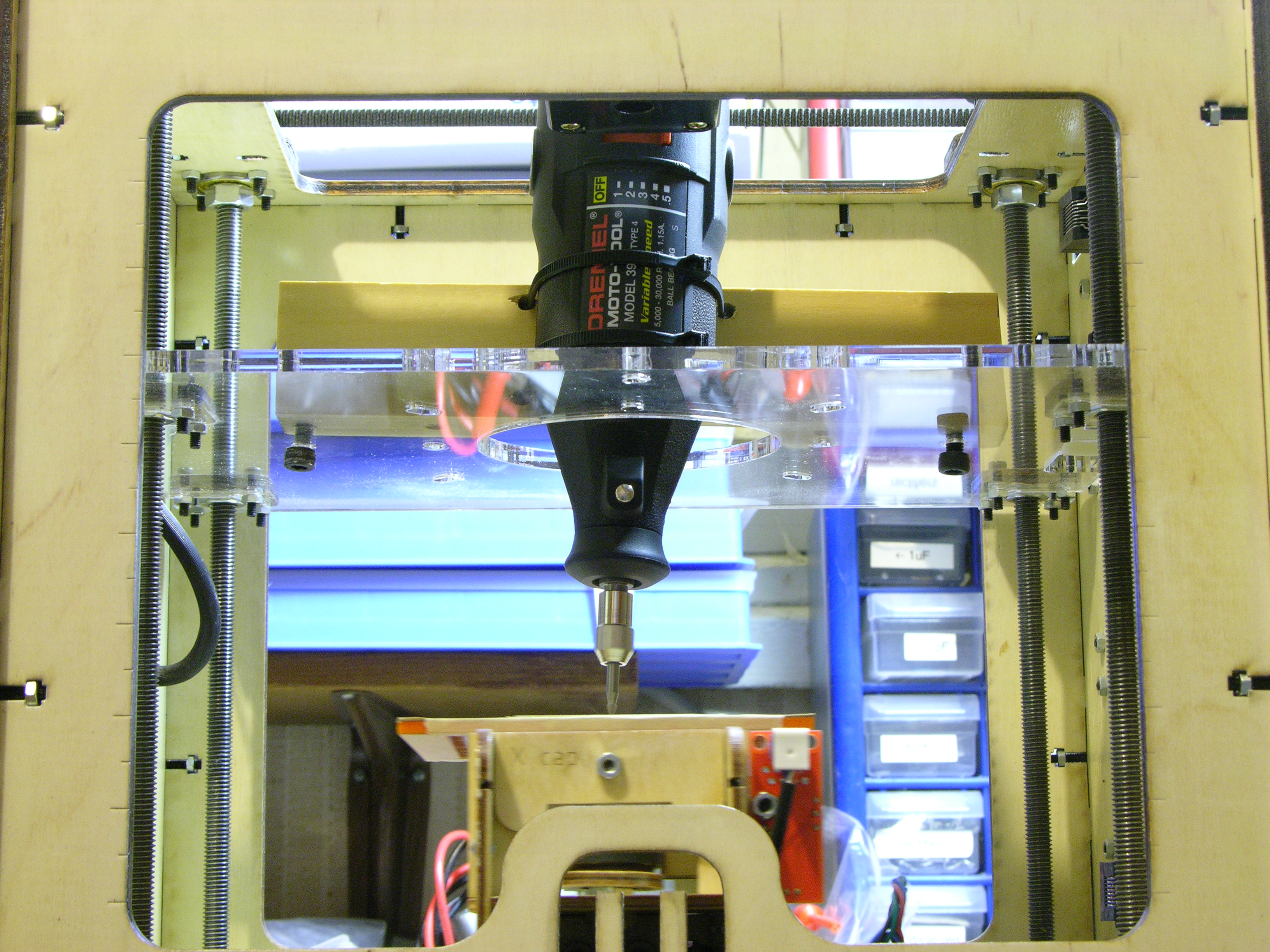
Scrounged up an SD card, copied the code to it, and printed from the card. No Unpause, no Stretch, no tricks. More than an order of magnitude better than any holes I’ve printed before.

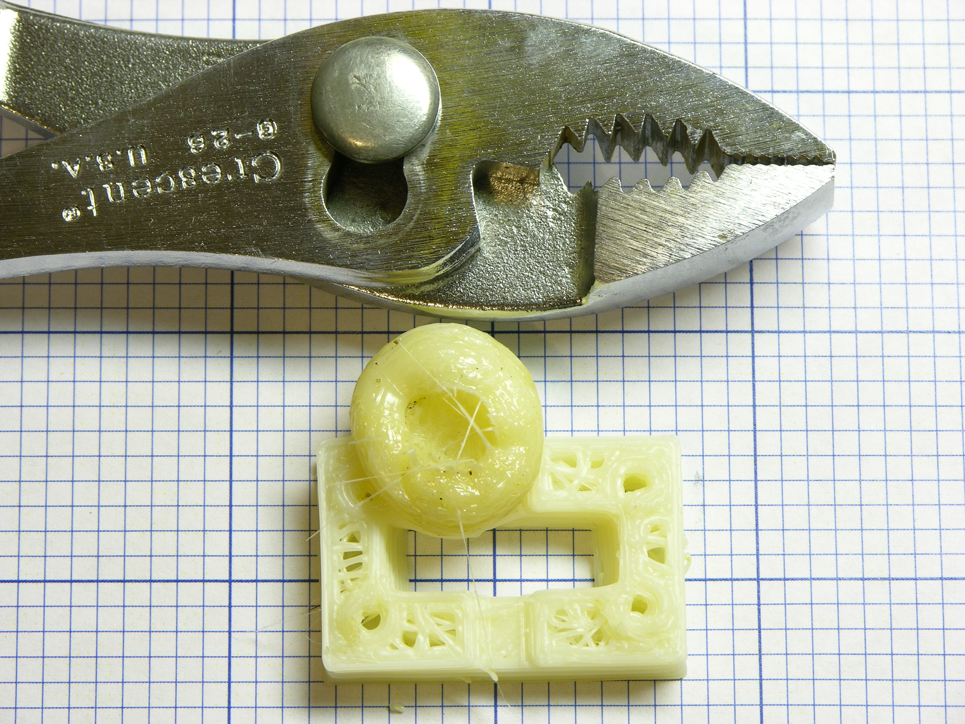
The bearing fits perfectly except where I impatiently squeezed the block too hard with pliers trying to pop it loose from the build platform too soon.

“Printing” the code from the MacBook to the card took 15 minutes. Printing from the card took 18 minutes. The similarity of those two times demonstrates that USB-serial transmission speed to the CupCake (and reception thereat) is much slower than I realized. It’s easy to see how the transmission becomes the bottleneck when sending many small steps around tight circles.

Given the widespread knowledge in the larger RepRap community about the advantages of designing (particularly) small holes as low-edge-count polygons instead of circles, I am genuinely surprised that Skeinforge doesn’t have a module to reduce tight curves, with specifications for things like maximum number of segments, minimum degrees of arc per segment, and minimum segment length.

Yes, I’ve had a couple of significant breakthroughs in my CupCake usability this weekend. I’ll cover them when I have a few moments.

Huge Blob

ABS blob created on MakerBot CupCake when laptop battery died

And a word to the wise: If you’re still printing directly from your computer, don’t walk away when your laptop battery is about to die.

Guest Post: LEDs and Ping-Pong Balls to Replace 10W Sign Bulbs

Friday, March 25th, 2011

My friend Cort Buffington doesn’t have an active blog of his own but is doing interesting things with 110VAC light bulbs and is looking for ways to migrate to LEDs.

Star Seq'r and disco ball

What follows is a write-up of his tests with LEDs and ping-pong-ball diffusers.

Cort’s Quest for 10W Sign Bulb Replacements

For some time I’ve been trying to figure out how to make an LED equivalent to a 10W colored sign bulb. Whether it be the G style intermediate base or the S style medium base. The big problem has been a diffuser. Sign bulbs are meant to be looked at, not to illuminate other things, so this is of paramount importance. I very quickly came across a LOT of information online with folks using ping pong balls, and Keith was just as eager as I to try this out. The initial tests with ping pong balls worked…. sort of. Ping pong (or beer pong if you’re in college) balls do work, but there are a couple of immediate problems:

(more…)

PCB Milling with the MakerBot CupCake: Aluminum Leveling Platform

Saturday, March 19th, 2011

Last weekend I got my Dremel rigidly mounted in my CupCake for PCB milling, but the platform holding the PCB was attached with double-stick foam and was being deflected by the milling bit cutting the copper, causing considerable deviation from the intended milling path.

Leveling platform in MakerBot CupCake

Last night Steve cut some more aluminum plate for me and today I assembled a rigidly-mounted leveling platform to replace the stock build platform. The lower plate has holes matching the machine screws attaching the top of the Y stage, and I used slightly longer screws to bolt through both the aluminum plate and the original wood top into the Y carriage.

Leveling screw with nylock nut, upper view

I drilled holes in the corners, tapped the upper plate, and enlarged the holes in the lower plate. The socket-head cap screws spin freely in the lower plate while adjusting the upper plate’s height (I used a continuity meter to check when the milling bit was just barely touching the plate in each corner); then the nylon-insert nuts lock the screws in position. The whole assembly is quite rigid once tightened.

A number of designs for leveling build platforms use only springs between the two plates. I was concerned that without a nut, the machine screws might back out under vibration. Also, when extruding, having a platform with some give reduces the damage if you miscalculate the Z position and gouge the platform; but for milling, the whole point of this replacement is to remove any play in the platform.

PCB milled in MakerBot CupCake

The results were not tremendously better than before (left board, top row of pads; right board from commercial mill for comparison), so I slowed the feed rate to .1″ per minute and let the mill finish the rest of the board for five hours, just to see whether I could produce usable traces. The traces cut at an outrageously slow feed rate are much better than previous results, but still a bit, shall we say, interpretive for my taste.

Having watched the Dremel bit trying to cut the copper and having tested it handheld out of the machine, I do recognize that it’s not the right bit for this job. I have some carbide engraving bits recommended by Pierre (exuinoxefr) on the way from Hong Kong, and I think they’ll make a significant difference. In April.

Meanwhile, note the three pads in the center of the board. Even at only one stepper motor step per second, the board took a very consistently incorrect path under the toolhead. Also note that the diagonal lines look like they were drawn with a left-handed quill pen — NE/SW lines are thicker than NW/SE.

I believe this is caused by the considerable play between the original CupCake bushings and the guide rods. Tighter bushings would cause more friction, so they were chosen for a bit of a loose fit. Even though the platform is now rigidly mounted on the Y carriage, the Y carriage wiggles on the Y guide rods and the X-Y carriage wiggles on the X guide rods.

I’m extremely interested in the Mendel-inspired replacement X-Y assembly by Thingiverse contributor “twotimes.” It replaces the bushings with sets of roller bearings spaced around the guide rods; the bearings can be tightened against the rods and still roll smoothly. I intend to get in touch and ask whether it successfully removes the play from the carriages.

Leveling platform in MakerBot CupCake, closeup

Although my immediate interest is whether I can use the CupCake that I already own as a PCB milling machine, the enhancements I’m making will improve it as a filament deposition machine as well. The lack of leveling in my heated build platform prevented me from printing larger models; I’ve already drilled my heated platform to fit interchangeably into this new system. Smoother X-Y action from a replacement carriage can only help, too.

PCB Milling with the MakerBot CupCake: Aluminum Z-Stage Supplement for Rigid Dremel Mounting

Sunday, March 13th, 2011

In my previous attempt to trace-isolation-mill a PCB with my MakerBot CupCake, the CupCake’s entire acrylic Z platform (intended to support the light weight of the filament heater and extruder) was flexing under the torque of the Dremel bit dragging through the copper layer of the PCB.

MakerBot CupCake with aluminum Z-stage reinforcement and Dremel mount

This week I picked up 1/4″ aluminum plate at the yard to reinforce the Z stage and support a more rigid Dremel mount. Steve Atwood printed the DXF of the MakerBot Z stage mechanical drawing for me, which I used as a template to drill and tap holes matching those in the acrylic (forgetting, unfortunately, to double-check the accuracy of the feed rate on Steve’s inkjet printer — but I compensated for the resulting aspect ratio problem with a file).

MakerBot CupCake with aluminum Z-stage reinforcement and Dremel mounted

I put together a good-enough Dremel mount with plastic from the visual arts scrap bin. Initially I lined the mounting hole with foam weatherstripping, but the Dremel was wiggling just a bit even with the clamp tightened down. It’s less wiggly without the foam.

Circuit board milled on MakerBot CupCake

The multi-pass milling looks like someone applied a GIMP randomizing filter to the original pattern, but at least the bit is consistently cutting the copper. The Dremel mount isn’t flexing any more — the irregularity is from the double-stick foam I used to attach the milling platform to the XY stage; the platform and board were swaying significantly under the bit.

PCB Milling with the MakerBot CupCake and a Dremel (Almost)

Monday, March 7th, 2011

Dremel mounted in MakerBot CupCake (lower view)

My Dremel’s spindle had much more solid bearings than the Handy Grinder, so I mounted it in the CupCake tonight to try milling with it.

Dremel mounted in MakerBot CupCake (upper view)

It fit even worse through the Z stage than the Handy Grinder, but I remember having said something about the drill not even needing to be vertical as long as the bit’s tip made contact with the workpiece.

Dremel milling PCB in MakerBot CupCake

The XY platform wasn’t quite level (deeper cutting on the right than the left); but the real problem was that the Z stage was flexing. Not lifting off the Z stage guides — I could feel the acrylic bending as the tool direction changed. This demanded backing off the Z axis to an extremely shallow, ineffective cut to keep the milling tip from tracking the cutting direction as it did with the Handy Grinder.

Increasing the rigidity of the Z stage by bolting a large plate to it while mounting the Dremel is my top priority for getting closer to usable performance.

PCB after milling attempts

Straight off the mill after a variety of different attempts on the same workpiece. Parts of it almost look usable …

PCB after milling attempts, sanded

But sanded, it’s clear that in most places the bit barely scratched the copper and wasn’t even close to scoring through, because of the obligatory shallow cut.

PCB Milling with the MakerBot CupCake (Almost)

Sunday, March 6th, 2011

I crave a CNC mill for trace-isolation milling prototype PC boards and I haven’t managed to get my CupCake filament deposition machine calibrated so I can use it. (Build platform leveling and filament feed are my current showstoppers. I’ll get back to it.)

I knew that someone had proposed mounting a Dremel in place of the CupCake’s extruder and that MaskedRetriever had modeled a mounting bracket; but curiously, I haven’t heard any more about using the CupCake for milling. Surely someone has done it; I just haven’t run across it.

Last night while I was asleep, the facts and the immediacy of the situation came together: EAGLE can output trace-isolation g-code and ReplicatorG reads g-code and drives the CupCake. Really??? PCB trace-isolation milling is that simple???

Yes. Yes it is.

Circuit board layout drawn with pen in MakerBot CupCake

(more…)

Hammond XB-2 Drawbar Decoding Diagnosis and Repair

Saturday, March 5th, 2011

A couple of weekends ago I took the two XB-2s that I had (at the time) over to Ron’s shop to have a little more room to spread out and test things. Like real Hammond tonewheel organs, the XB-2 has “drawbars” that represent different harmonics (or subharmonics) of the fundamental frequency of each key being pressed; you draw out the bars to mix different amounts of the different harmonics to get the timbre you want. This is additive synthesis at its most visceral.

Hammond XB-2 drawbars

On the XB-2, the drawbar positions (either live or recalled from memory) are displayed on an LCD below the manual (keyboard). In live mode, the bar graphs move in and out in synchrony with the physical drawbars.

Hammond XB-2 drawbar display

On one of the two XB-2s, the LCD bar graphs didn’t match the drawbars — a couple of drawbars appeared to work properly, but some didn’t work at all and others moved multiple bar graphs on the display. Since the drawbar decoding is a relatively independent section of the organ, it seemed like an easy repair to tackle first.

Hammond XB-2 drawbar schematic

The drawbar’s wiring harness plugs into the main board on J121, at the left of this section from the service manual. Each drawbar is a detented slide potentiometer, so variable voltages are arriving on J121. The section enclosed in the dotted line and marked not used truly isn’t populated on the circuit board, so I omit it from discussion.

The nine analog drawbar voltages are delivered to IC23 and IC24 (TC4051 analog multiplexers). The multiplexers receive their enable and select signals from the output of IC29 (74HC174 hex D flip-flop) which is latching signals previously delivered from the system data bus. (In other words, the 74HC174 is the drawbar select register; its own address is decoded elsewhere in the schematic.)

The chosen (enabled) TC4051 analog mux selects which input to pass to its output on pin 3, which is then op-amp buffered and delivered to the input pin of IC25 (BA9101 analog-digital converter). When selected (more system address bus decoding), the ADC writes the digital value of the drawbar’s position onto the system data bus.

Side note: For the drawbars only having nine detents (0-8), IC25 sure delivers a lot of bits of ADC resolution to the data bus.

I put a scope on IC23 (analog mux)’s output pin and I was able to view on the screen the time-division multiplexing of the drawbar positions (analog voltages) onto the single line going to the ADC. It mostly matched what I saw on the LCD, although there were some quirks with a few of the drawbar time divisions appearing narrower than others. Ignoring the odd widths and recording which drawbar occupied which time division:

Drawbar Time-Division Multiplexing Behavior
Drawbar 16 8 4 2 1 5 1/3 2 2/3 1 1/3 1 3/5
IC23 Pin 13 14 15 12 1 5 2 4 (IC24)
IC23 Input Good MB 0
(000)
1
(001)
2
(010)
3
(011)
4
(100)
5
(101)
6
(110)
7
(111)
(IC24)
Bad MB 0
(000)
1
(001)
7
(111)
7
(111)
0
(000)
1
(001)
7
(111)
7
(111)
(IC24)

On the working XB-2 motherboard, the drawbars were selected and sampled in numerical order. On the broken motherboard, as you can see, any time the analog mux’s select bit A1 was enabled, the mux behaved as though bits A2 and A0 were enabled as well. Further, select bit A2 didn’t work on command as it should when drawbars 4-7 should have been chosen.

4051 Address Pins
Name C B A
Function A2 A1 A0
Pin 9 10 11

It could be a bad 4051 mux; but as we had already replaced a leaky electrolytic capacitor in the neighborhood, it seemed worth another look at the circuit board first. The 4051′s select lines are on pins 9-11, and what’s this?!

Hammond XB-2 main board, drawbar section

I became suspicious of a damaged via on a trace that turned out to connect to pin 9 (A2). A continuity test showed that the via — even its top side — was no longer connected to IC23; the trace up to the via had been eaten away by the leaking capacitor. The via — even its top side — did have continuity to its next stop on the PCB, so the via itself was intact.

Ron heated the solder that had wicked into the via during reflow, inserted a piece of wire-wrap wire, and soldered the other end directly to IC23 pin 9. The drawbars now work perfectly. I suspect the floating select input on the CMOS mux was picking up enough signal from the PCB trace inductively coupled to its neighbor to trigger.

My hypothesis is that the previous owner put the keyboard away because of larger (ROM / CPU / Muse) problems; the capacitor leaked and damaged the drawbar multiplexer trace while it was sitting idle; and the owner never even knew about the drawbar problem. At any rate, it was easily fixed and the troubleshooting was a rewarding mental exercise.