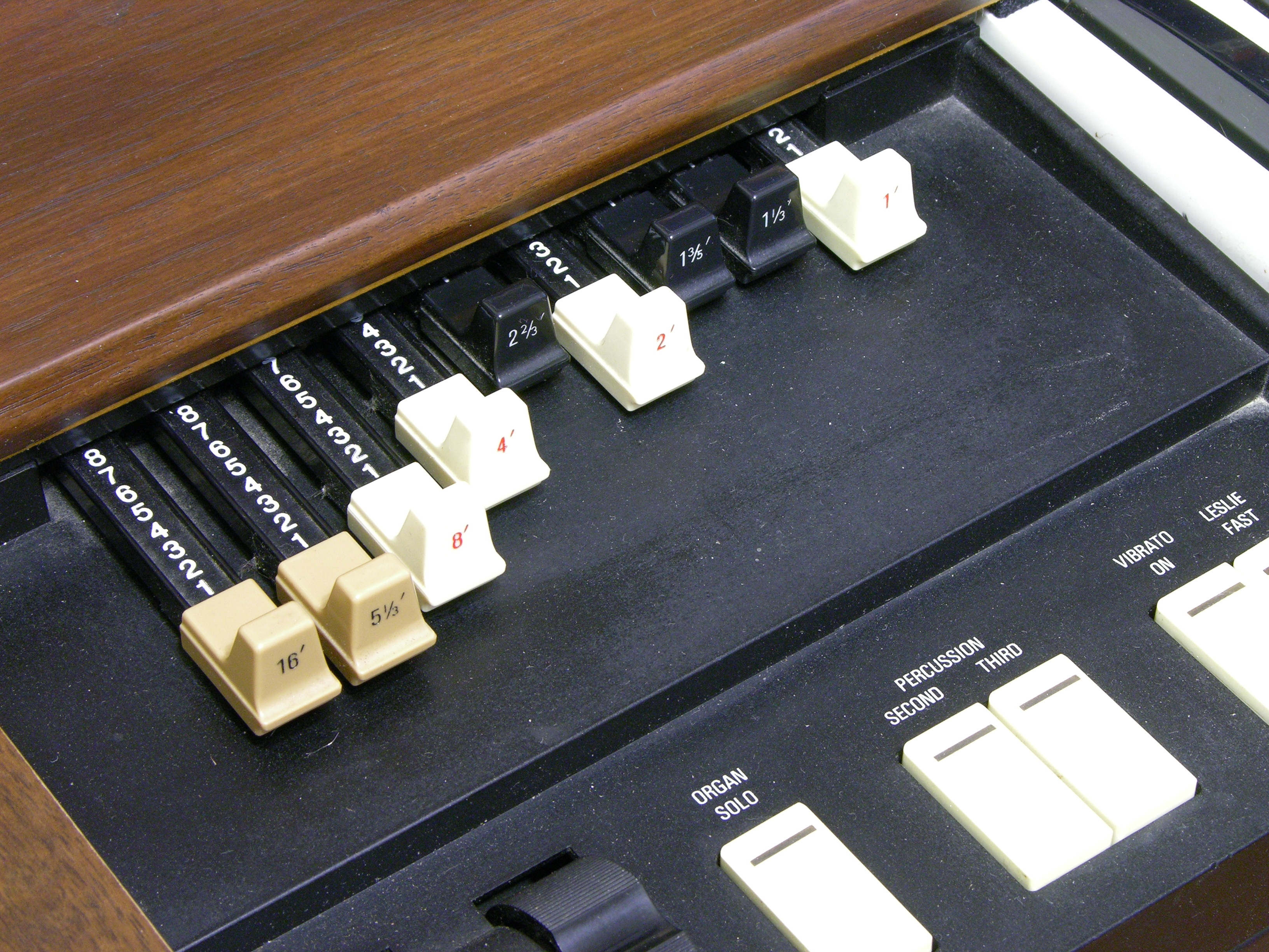
A couple of weekends ago I took the two XB-2s that I had (at the time) over to Ron’s shop to have a little more room to spread out and test things. Like real Hammond tonewheel organs, the XB-2 has “drawbars” that represent different harmonics (or subharmonics) of the fundamental frequency of each key being pressed; you draw out the bars to mix different amounts of the different harmonics to get the timbre you want. This is additive synthesis at its most visceral.
On the XB-2, the drawbar positions (either live or recalled from memory) are displayed on an LCD below the manual (keyboard). In live mode, the bar graphs move in and out in synchrony with the physical drawbars.
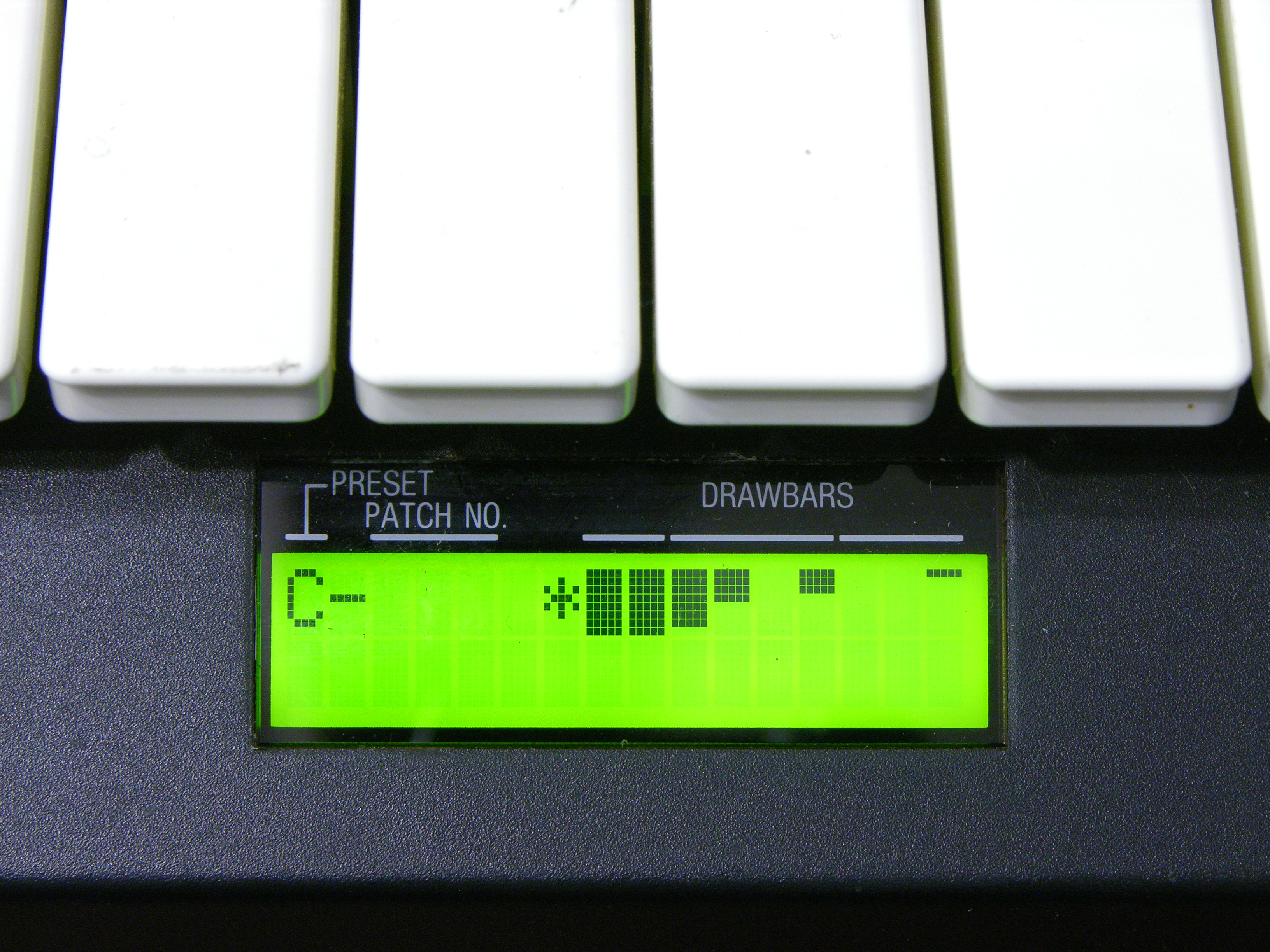
On one of the two XB-2s, the LCD bar graphs didn’t match the drawbars — a couple of drawbars appeared to work properly, but some didn’t work at all and others moved multiple bar graphs on the display. Since the drawbar decoding is a relatively independent section of the organ, it seemed like an easy repair to tackle first.

The drawbar’s wiring harness plugs into the main board on J121, at the left of this section from the service manual. Each drawbar is a detented slide potentiometer, so variable voltages are arriving on J121. The section enclosed in the dotted line and marked not used truly isn’t populated on the circuit board, so I omit it from discussion.
The nine analog drawbar voltages are delivered to IC23 and IC24 (TC4051 analog multiplexers). The multiplexers receive their enable and select signals from the output of IC29 (74HC174 hex D flip-flop) which is latching signals previously delivered from the system data bus. (In other words, the 74HC174 is the drawbar select register; its own address is decoded elsewhere in the schematic.)
The chosen (enabled) TC4051 analog mux selects which input to pass to its output on pin 3, which is then op-amp buffered and delivered to the input pin of IC25 (BA9101 analog-digital converter). When selected (more system address bus decoding), the ADC writes the digital value of the drawbar’s position onto the system data bus.
Side note: For the drawbars only having nine detents (0-8), IC25 sure delivers a lot of bits of ADC resolution to the data bus.
I put a scope on IC23 (analog mux)’s output pin and I was able to view on the screen the time-division multiplexing of the drawbar positions (analog voltages) onto the single line going to the ADC. It mostly matched what I saw on the LCD, although there were some quirks with a few of the drawbar time divisions appearing narrower than others. Ignoring the odd widths and recording which drawbar occupied which time division:
| Drawbar | 16 | 8 | 4 | 2 | 1 | 5 1/3 | 2 2/3 | 1 1/3 | 1 3/5 | |
|---|---|---|---|---|---|---|---|---|---|---|
| IC23 Pin | 13 | 14 | 15 | 12 | 1 | 5 | 2 | 4 | (IC24) | |
| IC23 Input | Good MB | 0 (000) |
1 (001) |
2 (010) |
3 (011) |
4 (100) |
5 (101) |
6 (110) |
7 (111) |
(IC24) |
| Bad MB | 0 (000) |
1 (001) |
7 (111) |
7 (111) |
0 (000) |
1 (001) |
7 (111) |
7 (111) |
(IC24) |
On the working XB-2 motherboard, the drawbars were selected and sampled in numerical order. On the broken motherboard, as you can see, any time the analog mux’s select bit A1 was enabled, the mux behaved as though bits A2 and A0 were enabled as well. Further, select bit A2 didn’t work on command as it should when drawbars 4-7 should have been chosen.
| Name | C | B | A |
|---|---|---|---|
| Function | A2 | A1 | A0 |
| Pin | 9 | 10 | 11 |
It could be a bad 4051 mux; but as we had already replaced a leaky electrolytic capacitor in the neighborhood, it seemed worth another look at the circuit board first. The 4051′s select lines are on pins 9-11, and what’s this?!
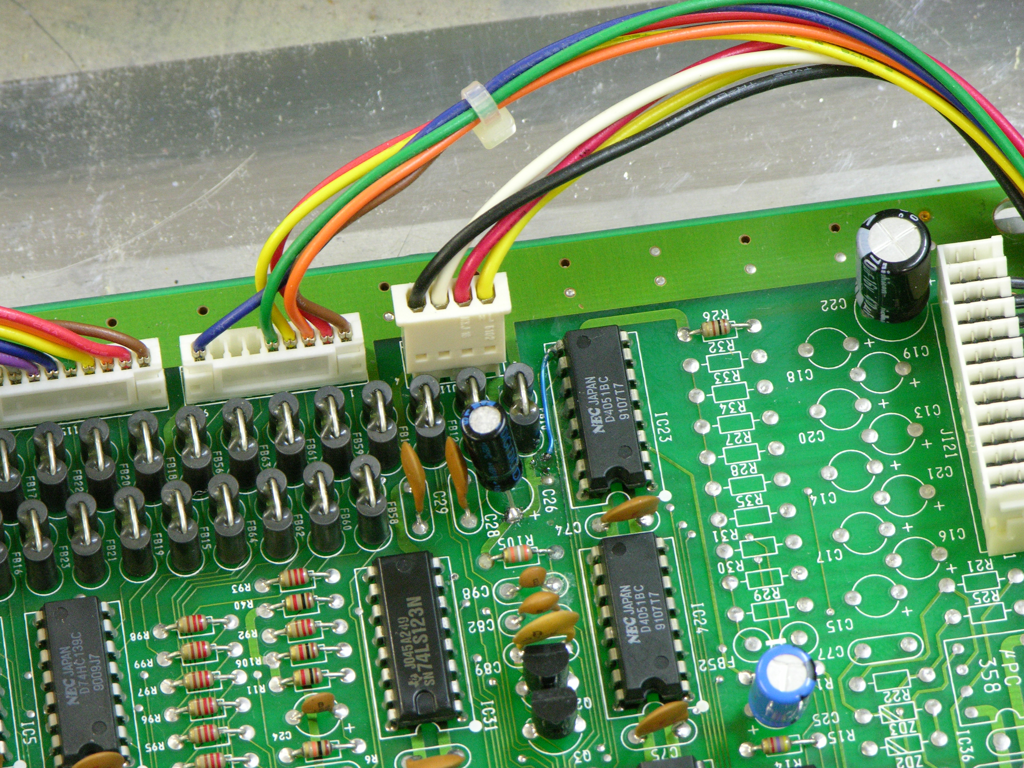
I became suspicious of a damaged via on a trace that turned out to connect to pin 9 (A2). A continuity test showed that the via — even its top side — was no longer connected to IC23; the trace up to the via had been eaten away by the leaking capacitor. The via — even its top side — did have continuity to its next stop on the PCB, so the via itself was intact.
Ron heated the solder that had wicked into the via during reflow, inserted a piece of wire-wrap wire, and soldered the other end directly to IC23 pin 9. The drawbars now work perfectly. I suspect the floating select input on the CMOS mux was picking up enough signal from the PCB trace inductively coupled to its neighbor to trigger.
My hypothesis is that the previous owner put the keyboard away because of larger (ROM / CPU / Muse) problems; the capacitor leaked and damaged the drawbar multiplexer trace while it was sitting idle; and the owner never even knew about the drawbar problem. At any rate, it was easily fixed and the troubleshooting was a rewarding mental exercise.
good find!!
found your site and had a question.
I have 2 Hammond XB-5′s
the processors have gone out from what i’ve been told and i looking for someone to help me fix at least one of them.
Is there anything or anyone you can suggest.
the XB-5 was my main axe and I”m really bumming about this.
thanks
Ted Andreadis
Ted, I’m not familiar with the XB-5s and don’t have any suggestions on how to go about getting them repaired, sorry.
I’m having a similar issue with my XB2. For me, my drawbars just aren’t working at all. I’ve checked to see if a connector came loose or if a capacitor went bad and I don’t see a single a single thing wrong internally. Would a similar approach have to be taken to getting the drawbars working again?
Hi I wonder if you could help, I have a Hammond xb2 series 1 Rev the display comes up I did a system reset and that all worked I also tested the draw bars and the display recognises them and displays when I ajust them also key data is registering via the LEDs on pcbs.
I have no sound output at all even the headphone socket.
Could you please advise I am a TVs engineer so I am very ok electronics and test.
Kind regards.
Martin.
In need of the main board for a Xb2, or the mother chip?
Any information to this part?
Thanks, Bill
I need the main board or chip for my Xb3
Any Help?
I have also a XB-2. Pressing the keys makes quick random noises but nothing near from a musical note. Drawbars looks fine.
I have expertise on Digital Electronics; got the keyboard on a flea market and would like to revive it as a hobby. It has ver. 2.0 Roms.
At this time I’m building an microcontroller circuit that at first produces the same sound (without effects) from the classical B3 via MIDI. Information about the circuit is available on the Internet. I’m highly interested in to know well how the XB-2 generates the sound, so I can diagnose the actual failure.
Anyway, if someone has some XB-2 damaged main PCB I would like to buy for parts if cheap; the first try is to make the XB-2 to live.
If it works, I could copy the roms to share.
Keith,
Have you worked or know about the protocol of the signaling waveforms between the keyboard and motherboard of the XB2 ?
I’m working on a interface for the manual keys board (MN50020PGV Gate Array IC) to use with a custom microcontroller.
CPU reads 7 data lines (KDB0..KDB6), also the KDSTB line.
CPU commands the MN50020PGV with 3 lines (KDTREQ, KDTACK and KRST).