Archive for February, 2008

Homebrew SMT Probe Tweezers

Saturday, February 23rd, 2008

Closeup of SMT probe tweezers in use

Some surface-mount resistors have their values printed on them, but all 1206 and smaller SMT capacitors that I’ve seen are completely blank. The only way to determine their value — after salvaging, that is — is to measure them.

My multimeter has a capacitor tester, but its connections are slots in the body of the meter rather than the regular probes, so it doesn’t work at all for SMT capacitors. (In fact, most salvaged capacitors’ leads are much to short to make contact with the meter’s sockets.) Lately I’ve been plugging a couple of long wires with tinned ends into the meter so I can use the other ends to check the values of SMT capacitors on my workbench.

This is a pain.

Ever since I started salvaging SMT components, I thought it’d be great to have a pair of tweezers wired as meter probes — grab the component, pick it up to put away, and check its value all at the same time. There actually are such things available, but the ones I’ve found start at $35 with a custom connector for that manufacturer’s meter. Not much to my liking.

I figured on building my own, maybe by finding a pair of plastic tweezers and gluing some kind of metal foil to the gripping surface. But what kind of metal? I was thinking about this on the drive to work Monday. Copper oxides rapidly and wouldn’t make good contact in the long term; so does solder. Silver would probably be okay. Gold would be perfect, but I have no idea where to get . . . wait a minute. Sure I do.

Circuit board about to be sacrificed

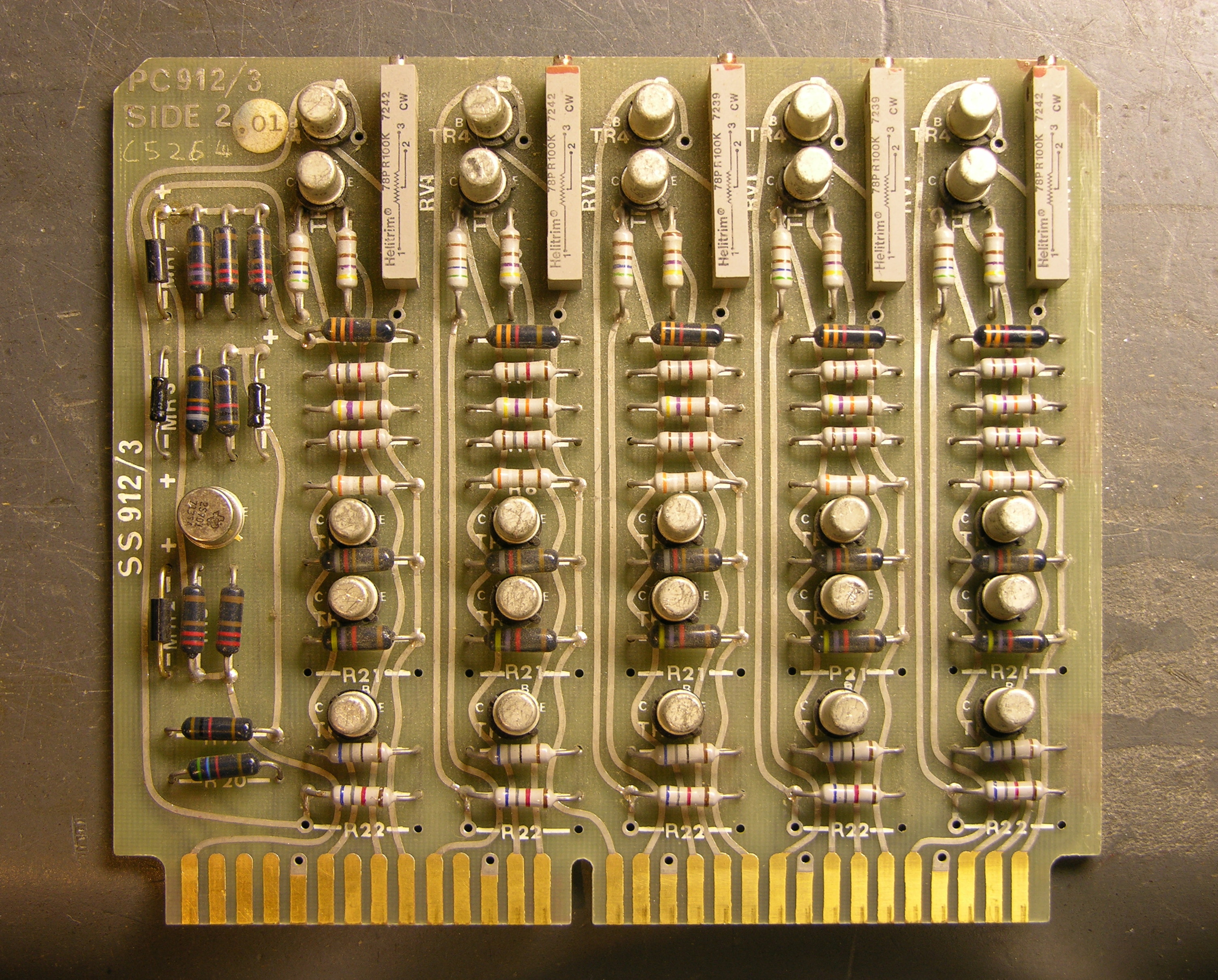
Monday night I sifted through my junk boxes and found a sacrificial circuit board with a nice, wide, gold-plated .156″-spacing card-edge connector on it. I desoldered everything from it the hard way — with a soldering iron — because this time it was about preserving the board rather than removing components as fast as possible.

Circuit board cut into strips

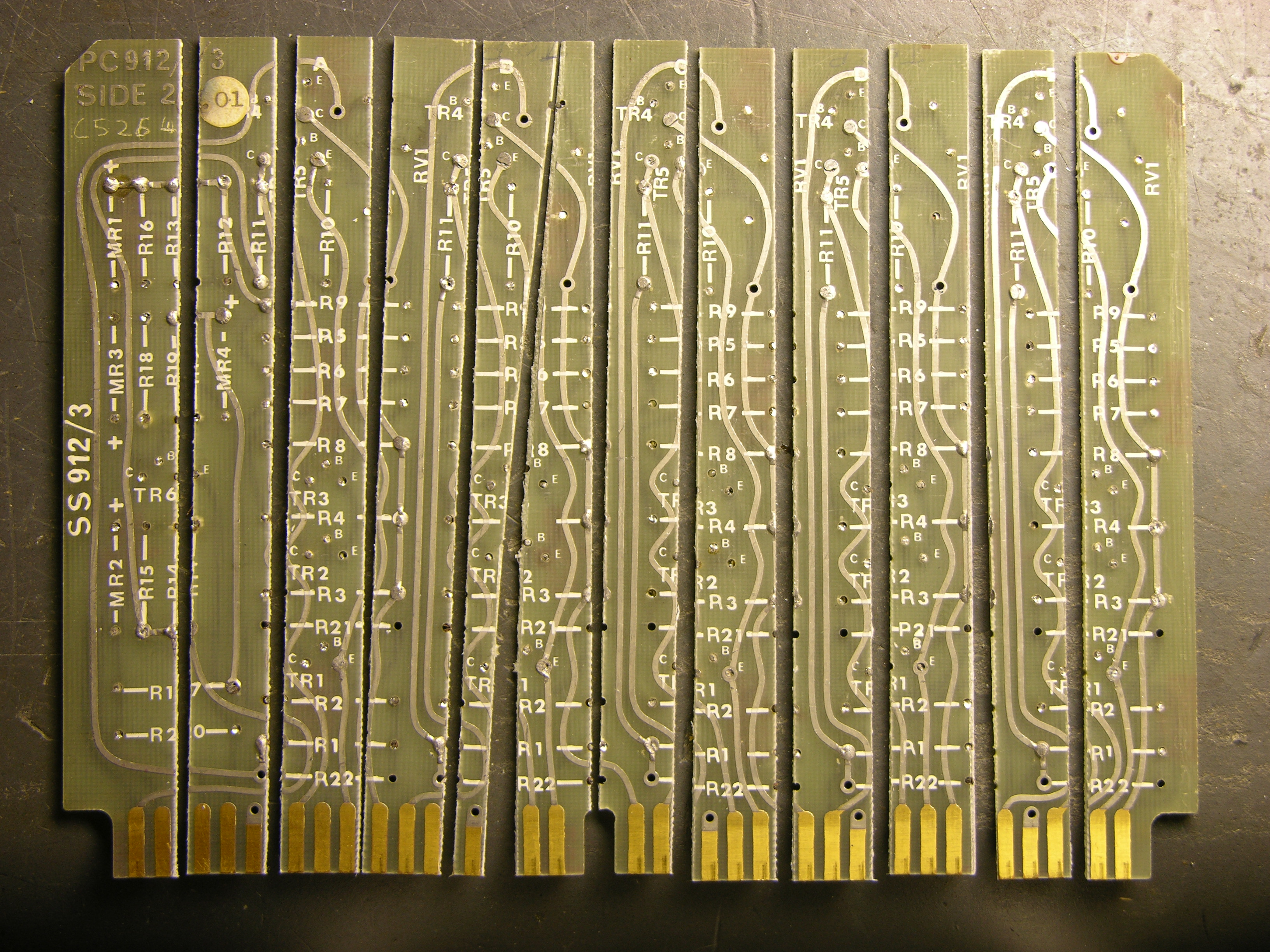
Tuesday I took the stripped board to the lab at school and used the PCB shear to cut it into strips, many of which are almost straight. That night I cut a pointed shape onto the end of two strips on my scrollsaw, doing a terrible job. I did slightly better on the next ones.

I used the bench disc sander to smooth them out and narrow the points to the width of the gold strips, then bevel the edges near the tips so the edges are sharp like a knife instead of thick like a PCB edge — it makes it easier to pick up very not tall SMT components. I also sanded the tip’s angle back from 90° to about 60°, since I’ll be holding these at an angle from my hand down to the workbench.

Two halves of SMT probe tweezers, wired

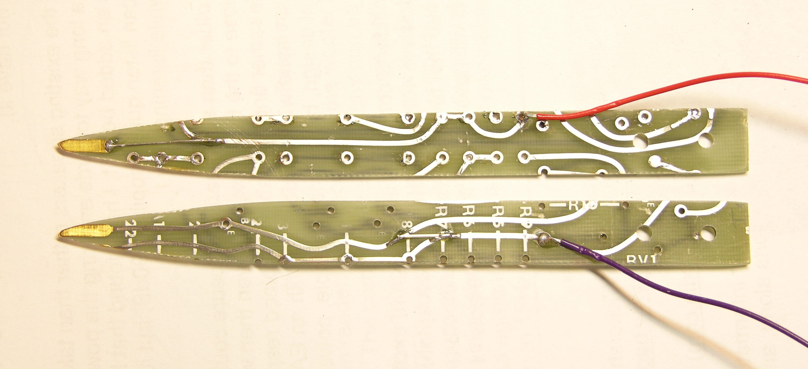
This afternoon I wet-sanded them very smooth, both faces and edges, then soldered a couple of jumper wires so I could use the existing traces to get from tip to handle, and soldered on two lead wires.

Completed SMT probe tweezers

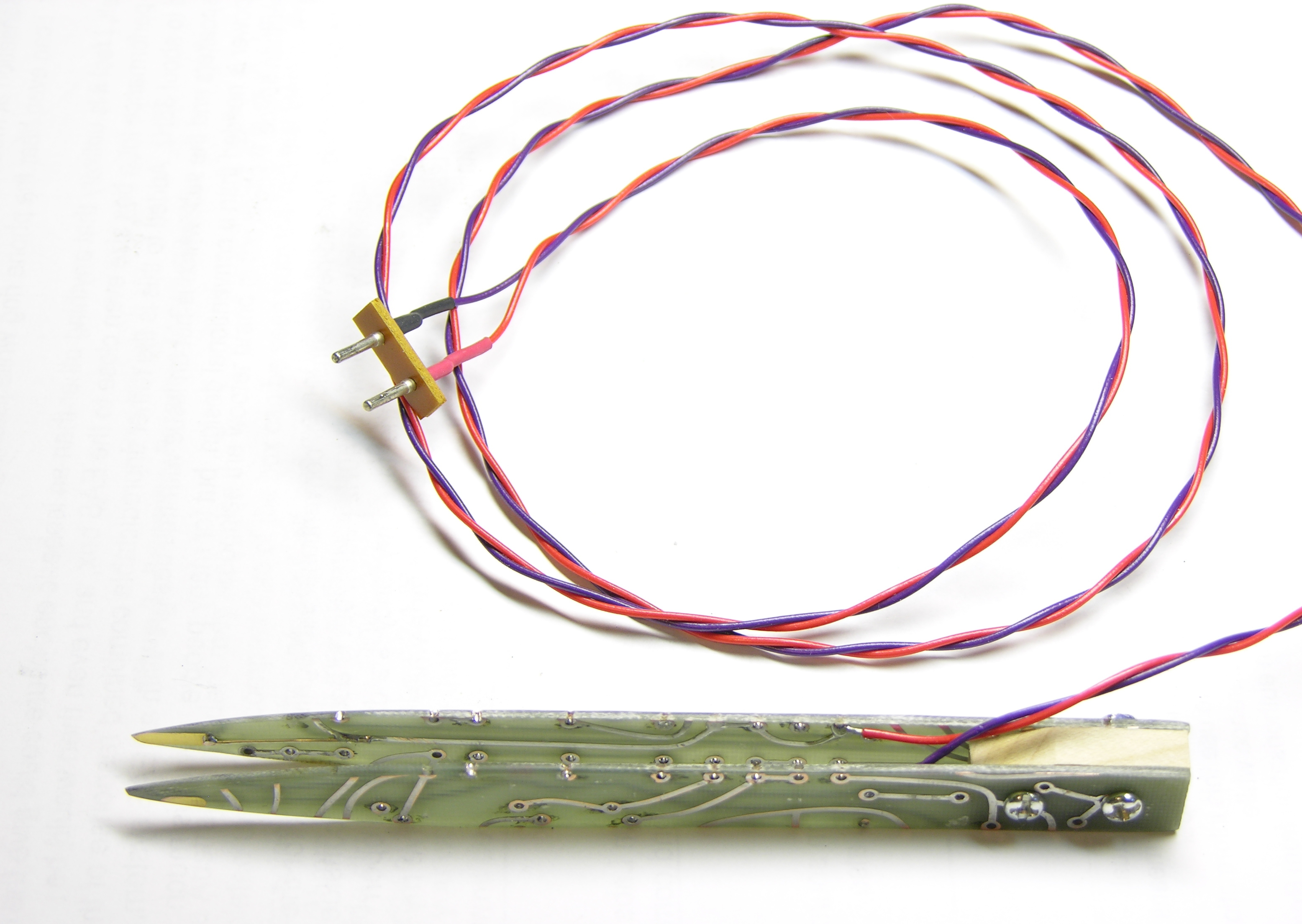
I taped the points together in alignment, clamped the handle end in a vise with a maple chunk in between, drilled holes through the works, and bolted it together. I had to cut one trace to keep it from contacting the bolts — it wouldn’t have shorted the two leads together, but I still didn’t want the bolts “live” on either side of the connection.

At the far end, I soldered to a salvaged plug (something from a CRT monitor yoke PCB, I think) to fit into the capacitor test slots on my meter.

SMT probe tweezers in use

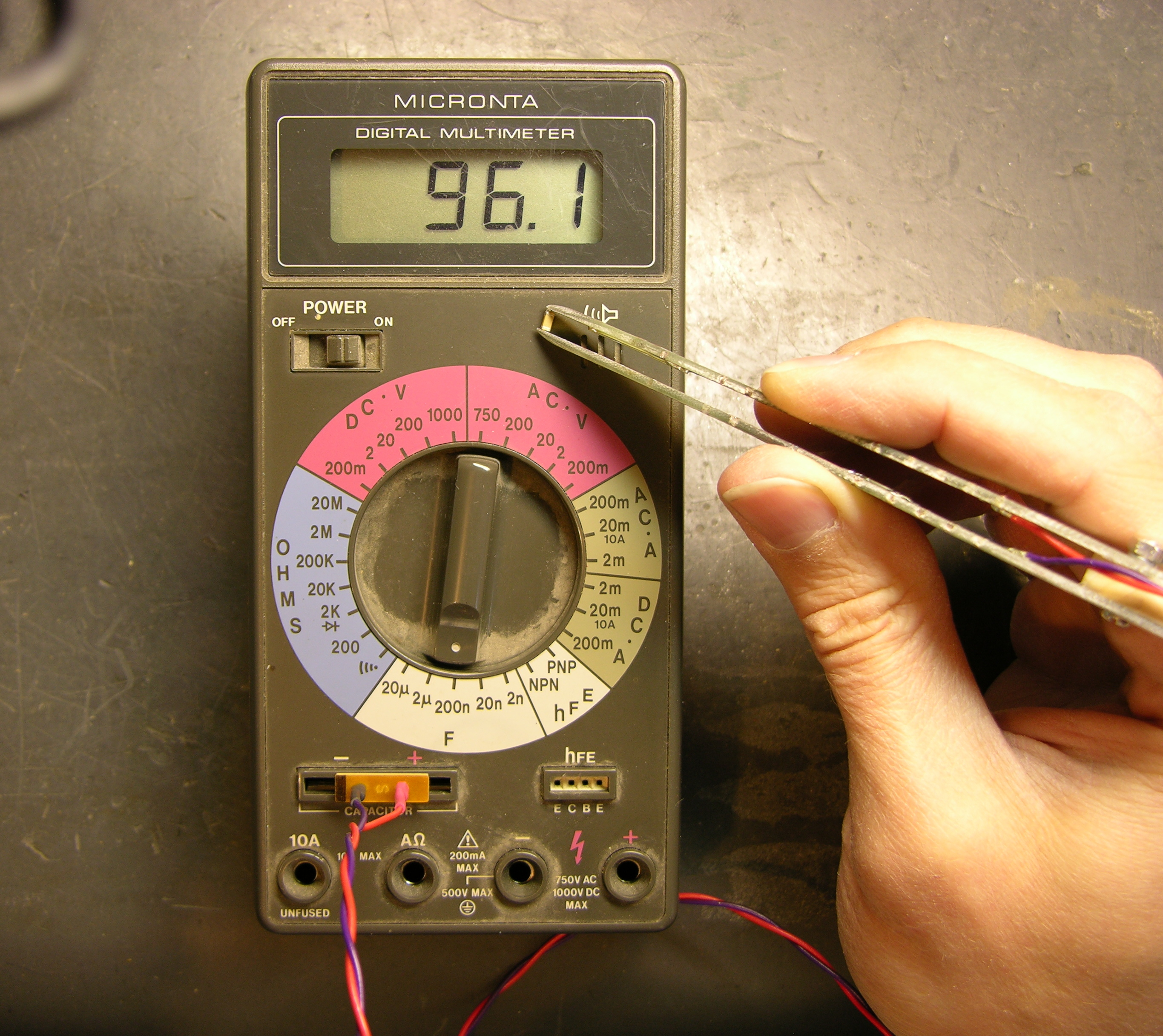
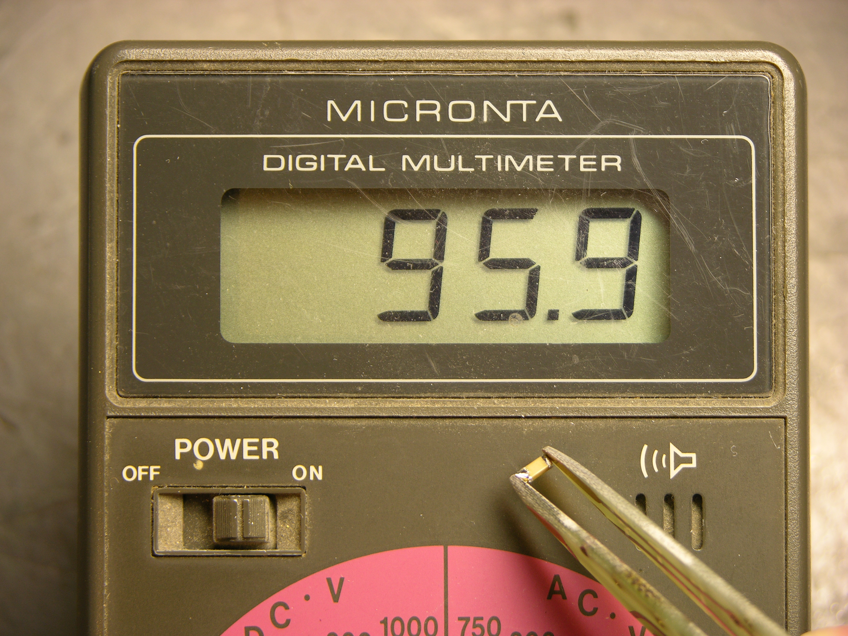
It works very nicely. The tweezer adds about 50pF to my measurements when it’s wide open, 60pF when I hold it as closed as I can without shorting; so probably 50pF when I’m holding a capacitor in it. That’s only a .05% error on the .1μF SMT capacitors I have in abundance, and I bet my meter itself is two orders of magnitude less accurate than that, so it really doesn’t bother me.

I think I have the jack that mates with the plug, and I want to build an adaptor to banana plugs so I can use this to double-check SMT resistor values, too.

Now I’m out of excuses not to put away all the SMT chips sitting out on my workbench. :-)

My First Arduino Shield

Sunday, February 17th, 2008

An Arduino “shield” is a PC board made to plug into the top of the Arduino, covering it (hence the name) and extending the Arduino signals to provide some extra functionality. Shields I know about are prototyping shields (“protoshields”), with a tiny breadboard on top; motor control, with H-bridge drivers to run motors, servos, and steppers; and ethernet, with a Lantronix Xport ethernet interface onboard. (I know there are shields from places other than Adafruit, but I really like supporting Lady Ada’s open-source hardware lifestyle, so I tend to look there first.)

After getting my Arduino, I had thought about getting a protoshield, but dismissed it pretty quickly — it seemed to me that the tiny breadboard on it would be too small to be useful for anything complex enough to be worth using the Arduino for. But Friday the Arduinos arrived for class, I agreed to do a demo/intro on Monday, and I realized it’d be a lot easier to do on a protoshield than on a separate breadboard.

With no time to order one before Monday, I had to construct my own over the weekend. I started with Lady Ada’s EAGLE schematic and board files (Creative Commons 2.5 Attribution Share Alike) and hacked them up for a single-sided board that I could etch quickly and easily. I took out her solder prototyping area, moved headers to align better with my tiny breadboard, changed up the LEDs and pushbuttons, and generally did enough work that I’m not sure I saved any time starting with an existing design. :-)

Homebrew Arduino protoshield

Here’s the result — ugly but very functional. I generally use breadboard wires cut and bent to length, so it matters to me that the header sockets are aligned with the breadboard columns and spaced a multiple of .1″ away. It works out very nicely.

Silkscreen Toner Transfer

Worth noting is that I used Cort’s idea of iron-on toner transfer for the silkscreen layer on the top side of the board.

Arduino protoshield PCB with iron-on silkscreen

After the copper is etched, the etch resist cleaned, the board tinned if you’re tinning, and the holes drilled, you print the silkscreen layer and do an iron-on toner transfer just like you would for etch resist. The main difference is that for appearance’s sake, you really want to get all the paper fibers scrubbed off of the toner — I probably spent half an hour in the sink with the toothbrush getting it clean.

I think the method is great; it’s just this instance that’s less than perfect. For one, this PCB is very dark, and the black toner doesn’t show up well; it’s much more readable on lighter boards. For another, the font is really smaller than is advisable for a toner transfer — I’m surprised it actually worked as well as it did.

It’s a very nice change to have labeled connections on a homebrew PCB.

Using It

I practiced my spiel tonight for class tomorrow, starting with the Arduino “Blink” sketch flashing the onboard LED, then:

  • plugging in the shield and jumpering in the green shield LED to blink as well
  • jumpering in the red LED and updating the sketch to alternate green-red-green, etc.
  • plugging a common-cathode RGB LED into digital pins 9-11 and updating the sketch to alternate red-green-blue-red, etc.
  • writing a pulse() function that uses analogWrite() (PWM output on pins 9-11) to fade an RGB color from dark to bright to dark and updating the sketch to pulse red-green-blue-red, etc.
  • wiring three more pushbuttons to digital pins 0, 3, and 6 (LOVE the ATmega’s internal pull-up resistors!) and changing the sketch to pulse a color dark-bright-dark on demand

It’s all pretty easy stuff, so the idea is that I’ll be able to do it while maintaining a stream of patter. We’ll see how that works out. :-) Still, it’s a nice introduction to a few of the capabilities of the Arduino and to how easy it is to just try things when you have a breadboard and a nice microcontroller development system.

So Do I Like It?

Using the protoshield tonight has convinced me that it’s great for a tiny demo, and too small to be useful for real work. :-| I’m not complaining, though; it’ll be fun to have around.

One thing that would help is the addition of a ground bus at the bottom — I waste a lot of column space leapfrogging ground to everywhere I need it. There’s room on my board that I’ll add a ground row on V2.

Credits

Original shield design by Lady Ada

PCB stock from Slim

Tiny breadboards from terminalcity

Iron-on toner transfer “silkscreen” method from Cort

LED Calculator Prototyped with LCD

Friday, February 8th, 2008

I still want to find a small LCD module for the LED calculator, so I can fit the whole thing into a box with a footprint about the size of a deck of cards. But for prototyping, I have a stack of 2×16 LCD modules about 3 1/2″ wide (viewable about 2 1/2″) from Slim, and Wednesday night I got one hooked up and working.

They’re Optrex DMC-16207 modules, and they seem to be using the Hitachi chipset that everyone uses, or at least an equivalent, although I didn’t know that at the time. Searching online, I had a hard time finding data on this exact module, but came across a mechanical drawing, a module user’s manual, and finally a full datasheet.

Interfacing the Arduino and LCD

I dived in and wrote my own LCD interfacing code. I found out in retrospect that there are several other Arduino LCD interfacing projects out there:

But all of them are using hard-coded delays to pause while the LCD processes commands, rather than checking the busy flag. To be sure, I’m doing the same thing right now in my first draft of the code; but I’m going to go back and clean it up to do it right.

Also, I haven’t checked all of them, but at least one is using digitalWrite() to manipulate each bit of the port register individually. Since I’m dedicating eight Arduino lines to the LCD’s I/O port, I can write the port register as a byte rather than twiddling individual bits, saving time and effort.

My goal will be to write a nice library module/class that encompasses these different approaches (8-wire vs 4-wire, busy flag vs hard-coded delays, read/write interaction vs hardwired write-only) and presents a clean interface to the programmer to select the options. Of course, for now, I just wanted to get it up and running.

I found this ATmega to Arduino pin mapping, which confirmed that Arduino digital lines 0-7 are PORTD lines 0-7. And the Arduino port register reference shows that DDRX and PORTX are defined as Arduino variables; so writing to a port is as easy as PORTD = $ff . It’s very nice that they left those low-level features exposed, even though in most cases it’s better to use the higher-level interface for portability.

Calculator Prototype

So here’s the work in progress.

LED calculator prototype with LCD on breadboard

The Arduino is getting power from USB and supplying 5V power to the LCD. The LCD contrast is hard-wired to ground. Although it actually looks pretty good right now, I’ll want to put in a potentiometer to adjust contrast. And I’m still using my bench power supply to run the LED circuit at 9V.

I don’t have a method built to select the voltage of the target circuit — the software is assuming 5V for now. The easy thing to do would be pushbuttons to bump the desired voltage up and down. It’d be kind of fun to do it with a spinny-wheel, although I’m not sure how much that would increase the cost, and I’m concerned about overengineering this thing if I really want to offer it as a kit. Maybe another potentiometer is a good compromise.

However the target voltage is selected, I need to determine the selectable range (which could of course be overridden by an owner with an AVR programmer). I’m thinking 3 – 15V in .1V increments. Is that enough?

LED Calculator Breadboarded

Saturday, February 2nd, 2008

After receiving some encouragement, I went ahead and breadboarded the measurement circuit for the LED calculator. Someone may suggest a better way to do it, but here’s what I’ve been carrying around in my head:

LED calculator drive circuit

R2, a 1KΩ potentiometer used as a variable resistor, controls the LED brightness. R1, a precision 100Ω resistor, limits the maximum LED current and acts as a sense resistor.

By measuring V1, we can calculate I1 = V1 / 100Ω. Since ILED = I1, we’ve determined the LED current. And VLED = V2 – V1, so we can determine the LED voltage drop as well.

The value of R2 isn’t critical. With a supply voltage of 9V and a very low LED drop of 1V, a 1KΩ variable resistor allows us to test LED currents down to (9V – 1V) / (1KΩ + 100Ω) ≈ 7mA, which is probably low enough for most applications. To be able to test lower, increase the range of R2.

Test Measurements

I built this much of the circuit and took measurements of a few different LEDs at a few different brightnesses, to make sure the potentiometer would really work the way I expected, and that I hadn’t made any stupid mistakes in the voltage calculations.

Color V1 V2 VLED ILED
green .71V 2.70V 1.99V 7mA
2.00V 4.04V 2.04V 20mA
3.45V 5.55V 2.10V 35mA
red .73V 2.55V 1.82V 7mA
2.00V 3.88V 1.88V 20mA
7.28V 9.24V 1.96V 73mA
blue .61V 3.61V 3.00V 6mA
1.12V 4.23V 3.11V 11mA
2.00V 5.27V 3.27V 20mA
5.56V 9.24V 3.68V 56mA

The measurements make sense — each LED’s forward voltage drop increases slightly as the current increases. If I remember my semiconductor theory correctly, that’s called the ohmic region of operation, in which a diode behaves like a very low-valued resistor.

Automating the Measurement

In a self-contained LED calculator, the voltages will need to be read by a microcontroller, which will also drive an LCD. For now, I used my Arduino and had it send results to the host computer.

Depending on the position of potentiometer R2, V2 can range up to the supply voltage of 9V (or whatever); and V1 can range up to the LED’s forward voltage drop less than that. I’m pretty sure the microcontroller’s A/D converters don’t like inputs over 5V, so I needed to divide V1 and V2 to lower their ranges before feeding them into the ADCs. I used two pair of precision 10KΩ resistors for that.

LED calculator measurement circuit

All put together on the breadboard, it looks like this.

LED calculator circuit, breadboarded

And with a little Arduino program running to read the inputs, scale from 1024 steps back up to a range of 5V and then double to compensate for the voltage division, and calculate all the values, I get this.

Output from LED calculator Arduino prototype

Putting It in a Box

I’ll probably program an Atmel chip directly, because I don’t need all the USB baggage. Even a Boarduino has prototyping parts on it that I don’t need here.

I need to think carefully about the LCD screen, to have enough room to display all the information and still be small enough to fit into a reasonable project box. A cell phone screen would be the perfect form factor, but really drives up the cost and complexity. I think about a 4×16 character display would be okay; 4×10 would be tight for the text and I’m afraid 4×20 would be too wide for the box.

LED 2.10V 35mA
DRV 8.4V 180ohm

Okay, 2×15 is a bare minimum. All Electronics has a 2×16 module that’s 4″ wide and another that’s 3.15″ wide, which suggests having to build the calculator in landscape mode. Not wild about that. Digi-Key has 4×16 starting at $27 and — hey! — a comparatively svelte 2.6″ wide 2×16 at $5.88.

Project Idea: LED Calculator

Saturday, February 2nd, 2008

When I want to know what value current-limiting resistor to use with an LED, the easiest thing to do is assume 5V supply / 15-20mA / old-school LED / 220-330Ω resistor, like we all learned from Forrest Mims in the 70s and 80s.

And then I tweak the resistor until the LED is as bright as I like, by trial and error.

Oh, most of the time I use my LED tester to estimate the current I need for the brightness I like. At $6-10, it’s indispensible. Also double-checks anode/cathode pinning and tells me if an LED is burned out.

LED tester

But running on a 7.2V supply (NiMH “9V” battery) with fixed current-limiting resistors designed for a 9V supply and low-forward-drop LEDs, it’s not really representative of what’s going to happen when I put a newer-chemistry LED with a 3.5-4V drop into my 5V circuit. So it’s back to trial and error.

I want a microcontroller-based LED tester/calculator that:

  • has a socket for the LED
  • has controls to set the target-circuit supply voltage
  • has a current knob to turn until the LED is at a brightness I like
  • displays on an LCD the target circuit supply voltage, the LED voltage drop, the LED current, and the value of resistor to achieve that current with that supply voltage
    (That is, all the facts about the LED I’m testing, and the resistor value I need to use in the target circuit)
  • is about the size of my existing LED tester

Note that the tester need not be running at the target circuit’s voltage; we can calculate resistor values for arbitrary voltages once we know the desired LED current. It does need to have a higher supply voltage than the forward drop of new-fangled LEDs, and I’m inclined to run it on a 9V for compactness and simplicity.

I’ve been kicking this around for quite a while, and I’d really like to make one. And publish the plans and code for DIYers and make circuit boards and kits for kitbuilders.

Is that the right feature set? I personally never put LEDs in series, but should the tester be able to calculate for that anyway? What else?