I now have a single digit prototype on my workbench counting away the seconds and flashing the colon. But it’s going to take a few posts to get there, starting with:
Making a PC Board (PCB)
Last week, I had got the PCB layout done (and redesigned to correct an aesthetic error) for a single prototype digit of the clock. Next, I needed to produce an actual board to see how well the design worked, and whether it actually looked right in operation. I’m not willing to spend $60+ on a 3″x4″ board, so commercial production was out. EAGLE has a User Language Program (script) to generate router instructions for milling away the copper around your traces (instead of etching it away), but Joel and I haven’t taken the time to figure out how to output a format that his drill machine can read.
That left me with etching the board myself. I’m used to drawing the traces by hand with a permanent marker, and having discovered EAGLE’s checkbox for printing a mirrored copy of the bottom-side traces would have made it a whole lot easier to draw all the traces correctly. I recently ran across another web page describing an etch-resist iron-on process using plain magazine paper (which unfortunately I didn’t bookmark), and I thought I’d give it a try.
Cutting and Drilling the Board
First, I needed a board with the through-holes drilled, because I’m pretty sure it’s easier to match the traces to the holes by hand than to align the traces correctly to drill the holes on the machine.
I needed a 3″x4″ piece of single-sided, copper-clad board. I have a huge piece of board from my friend/mentor Slim in Pittsburg, who was using it to keep the rain off of tarps in his back yard (or something like that):
When I need to make small boards, I cut a strip off of the end of the monster in some standard dimension (even inches), then cut the strip to length as needed. The carrier is bakelite and very brittle, so shears don’t work like they do with fiberglass; thus when I had cut off my 2″-wide strip, I used a hacksaw blade. It was very tedious, and I was looking for a better method, so Saturday I cut a 3″ strip by holding down a yardstick guide and scoring a snapline with the corner of a cheap chisel. I scored most of the way through before snapping, and it worked so well I cut the short pieces to length the same way, rather than on my scroll saw as I had done previously.
I actually had plenty of opportunity to practice, as I wanted to drill two prototype boards in case the first didn’t turn out, and I decided to drill the boards in a stack to save time, and I put them in the drilling machine upside-down (single-sided board, ‘member?), and I cut two more boards and got them right on the second try.
I’m only slightly ahead of myself here. Before making that particular mistake, I had generated an Excellon drill file out of EAGLE and took it to Joel’s house. DanCAM’s optimizer/translater didn’t like the format, so I compared it to another file I had drilled previously and hand-edited it into the same format. (This is on DOS using EDIT, mind you, because that’s what DanCAM wants to run under.) I think I’ve figured out how to make EAGLE generate DanCAMmable files directly, and I’ve written up the information on my EAGLE Circuit/PCB Layout Tips page.
Iron-On Decals
I knew you could purchase special “paper” that you could run through a laser printer, print the traces you wanted on your board, and then iron them onto the board and peel the paper away. In fact, Joel has a pack of this stuff that he’s been wanting to try for years, and asks if I want to test every time I’m building a complex board. I keep refusing, though, because I assume a sheet will only survive one trip through the printer, the boards I make are much smaller than the 8.5″x11″ sheets, I hate to waste the rest of a sheet, and I was leery of taping a smaller piece to a paper carrier.
So I was intrigued when I recently ran across postings describing a method I had heard of before: Print onto magazine paper (or overhead projector sheets). Supposedly the glossy paper releases the thermoplastic toner adequately when you iron it onto your clean copper board. With two (correctly oriented) copper boards on hand, it was worth a try. Plus I had a secret weapon: a stack of clean clay (glossy) paper salvaged from when I took out the trash and waste at a printing press, clear back in high school.
The first step was to clean the PC board that I was going to iron. I scrubbed it with 600-grit sandpaper to clean the surface and knock down the rough spots around the drill holes, then with 1500-grit to get it as smooth as possible.
I then printed the trace and pad pattern onto the clay paper, put it against the drilled board, and held it up to the light to align the pattern with the drilled holes. It turns out that my printer–an HP LJ 4M+ workhorse from Boeing Surplus that I’ve been using for years–prints slightly smaller than actual size, regardless of what kind of paper I have in it (so it’s not just slipping the rollers on my glossy paper). So the holes didn’t line up from end to end, and I had to cut the paper into three sections to get it to align well enough. I taped the sections onto the PC board so they wouldn’t slip, and I was good to go.
I ironed the paper onto the board as well as I could. In retrospect, I should have put a solid block or board underneath to support it from tipping and sinking into the ironing board’s pad, because the edges didn’t iron on nearly as well as the center. Although this picture is out of focus, you can see how large sections of traces are missing from the edges.
I found it intriguing that the only the front side of laser toner is black–the back side is white, as you can see on most of the traces above. Ha. Ha. That’s the surface of the paper carrier, of course, which stayed adhered to the toner even after soaking in water long enough to slip the rest of the paper off.
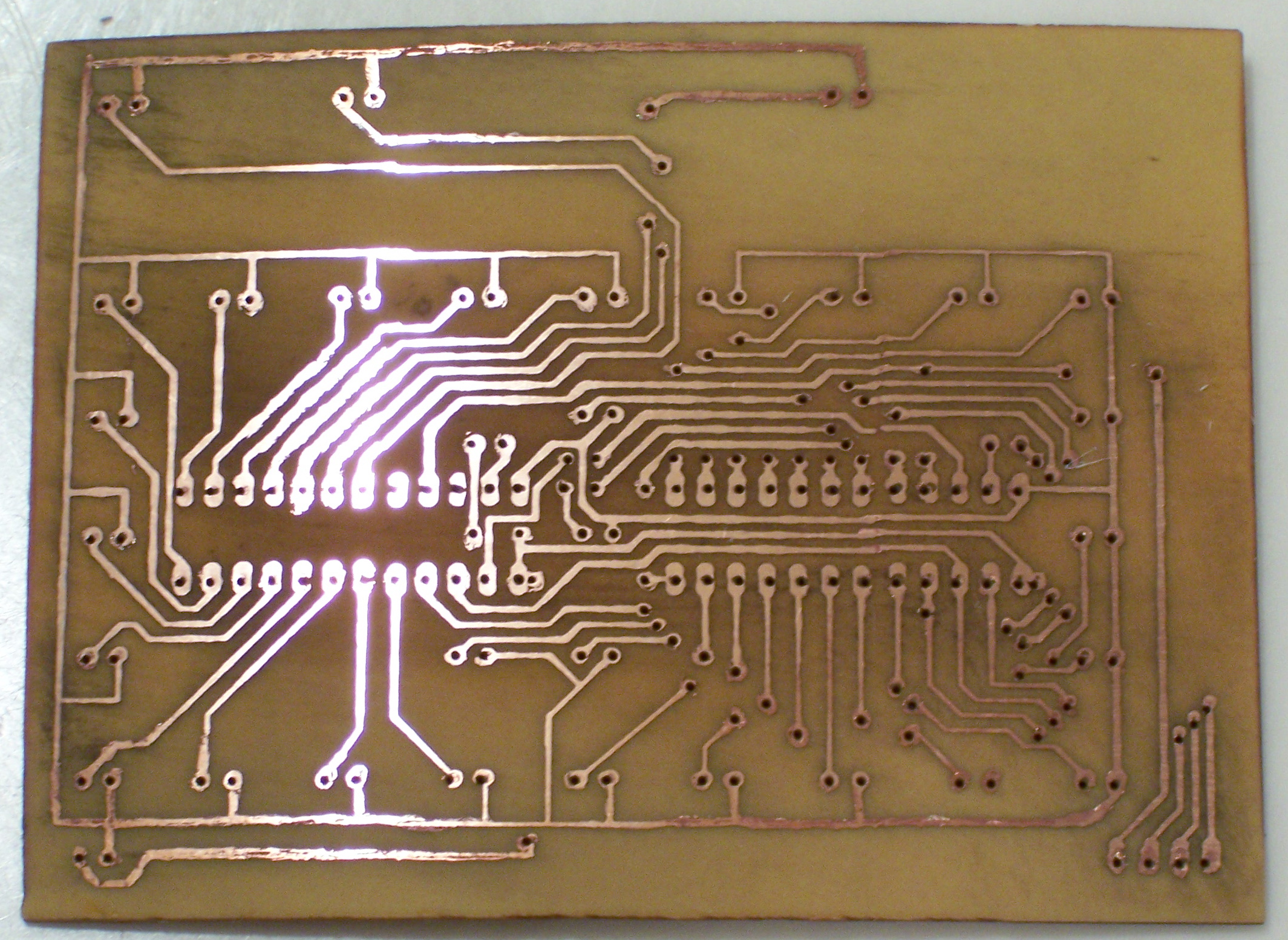
I drew in the missing traces with my trusty Staedtler marker, including touching up the gaps between the sections of paper I had cut apart. I etched in FeCl for about an hour, rinsed the board and touched up the marker traces again (the toner traces were still fine), etched a while more, and ended up with this, a fairly respectable little board.

Acetone takes both permanent marker and laser toner right off:
And it was time for assembly.