After knowing that the Voron 2.4′s Z limit switch and Z probe produce repeatable results, we’re almost ready to begin calibrating the heated build platform for optimal first layers. But since the goal is to achieve the right temperature for different filaments (at the very least, radically different temperature for ABS vs PLA, and quite likely somewhat different from brand to brand and even color to color), I’d like to know that the printer is setting the surface of the build platform to the temperature I’ve asked it to.
One could — and I will — empirically test the best temperature setting for different filaments. But done without knowing how accurately the printer is achieving the temperature that has been set, the results will be unique to that printer. I’d like to tune my filament temperature settings to work reliably across all my printers (for a given build surface).

Apparently this will require some compromise, as the steady-state temperature between the center and edge of the build platform varied by 6°C when the setpoint was 100°C, a considerable amount given that first layers are often printed with the platform 10°C hotter than remaining layers and this 10°C is believed to make a difference.
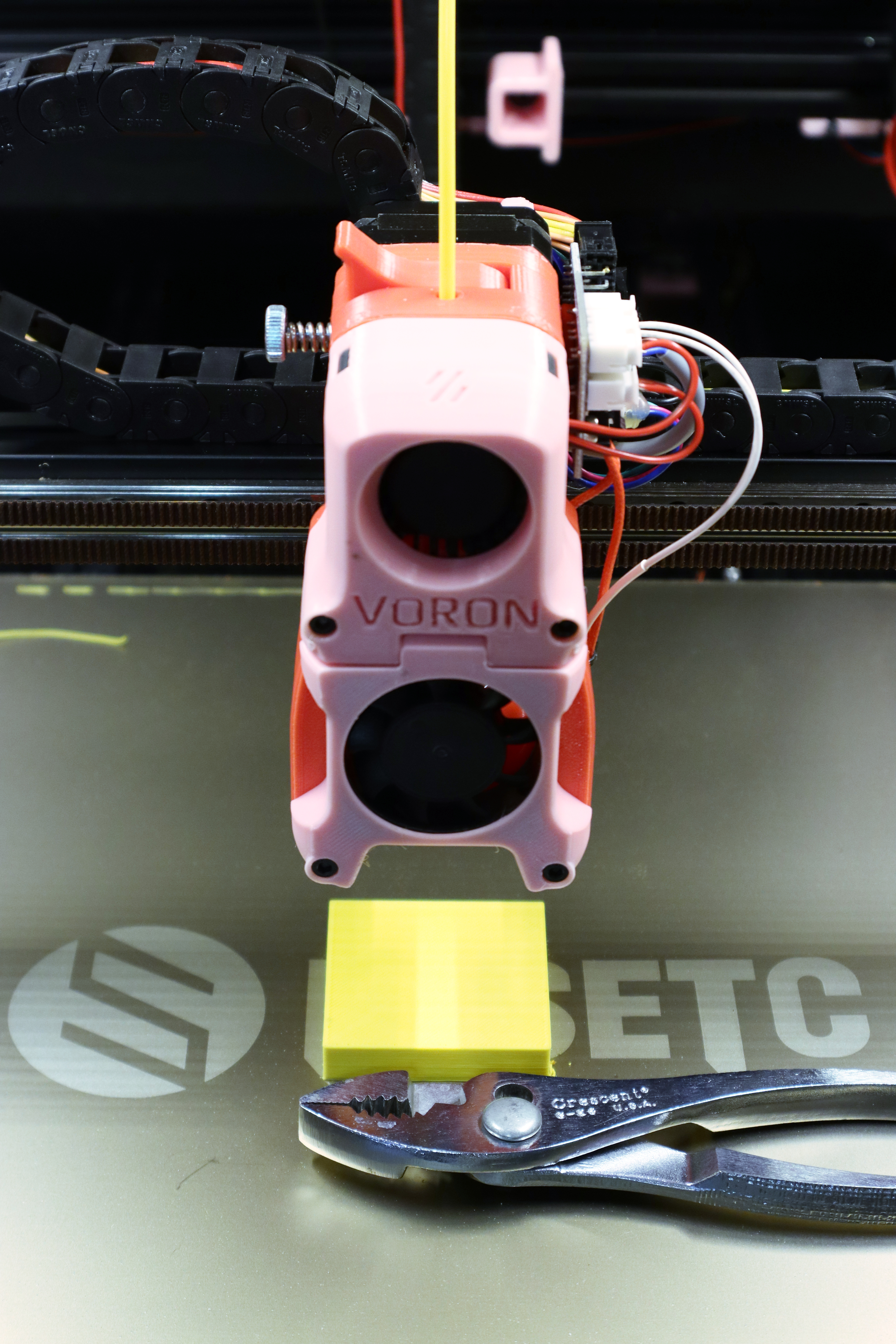
Let’s see how the platform temperature behaves with a Fysetc kit in factory configuration.