Archive for December, 2007

Arduino USB Auto-Reset Hack

Monday, December 31st, 2007

Older Arduino boards like mine have two annoyances associated with uploading software to them. First, you have to press the reset button (physically) to trigger the bootloader to expect new software from the host computer. Second, the Arduino waits allegedly 6-8 seconds (actually about 10 on mine) on every boot before starting your program, in case you might want to be uploading new software to it.

Small annoyances, to be sure, but they add up quickly when you’re trying to tweak a timing constant in a program and uploading software repeatedly. Thus in designing the latest Arduino, the Diecimila, the team addressed these two issues.

On the Diecimila board, they added a capacitor between the USB-serial chip’s DTR line (active-low) and the microcontroller’s reset line, so that the host computer can trigger DTR and pull down the reset for a moment, relieving you of pressing the button. In the new version (10) of the IDE, they added code to support that new functionality. And in the bootloader burned into the ATmega168 microcontroller, they shortened the boot wait time to a second or less.

All of that comes prepackaged for Diecimila owners; but owners of older Arduinos are resourceful and found how to adapt their own boards as well. The NG can be hacked by soldering a capacitor across two adjacent pads that appear to have been put there for that purpose. The Arduino serial can be hacked by stringing a capacitor between the serial connector and the reset line.

Arduino USB hacked for auto-reset, top side

But I have an Arduino USB, the first version to support USB and not yet a “next generation,” and I haven’t been able to find instructions on modifying it. It doesn’t have the pads already broken out like the NG; in fact, it doesn’t even have the same package USB-serial chip. So I muddled through, found the right pins, and did it myself. Works (mostly) great!

Finding the Right Pins

The page for the NG hack simply shows you physically where to put the capacitor on the NG board and doesn’t describe what it’s connecting electrically, which didn’t help me, as I needed to figure out where to put it on the physically different USB board. Fortunately, the page for the Arduino serial hack gives the critical information:

The retrofitting process consists on soldering a 0.1uF disc capacitor between the DTR pin [of the serial port or USB-serial chip] and the Reset signal [of the microcontroller].

Good enough!

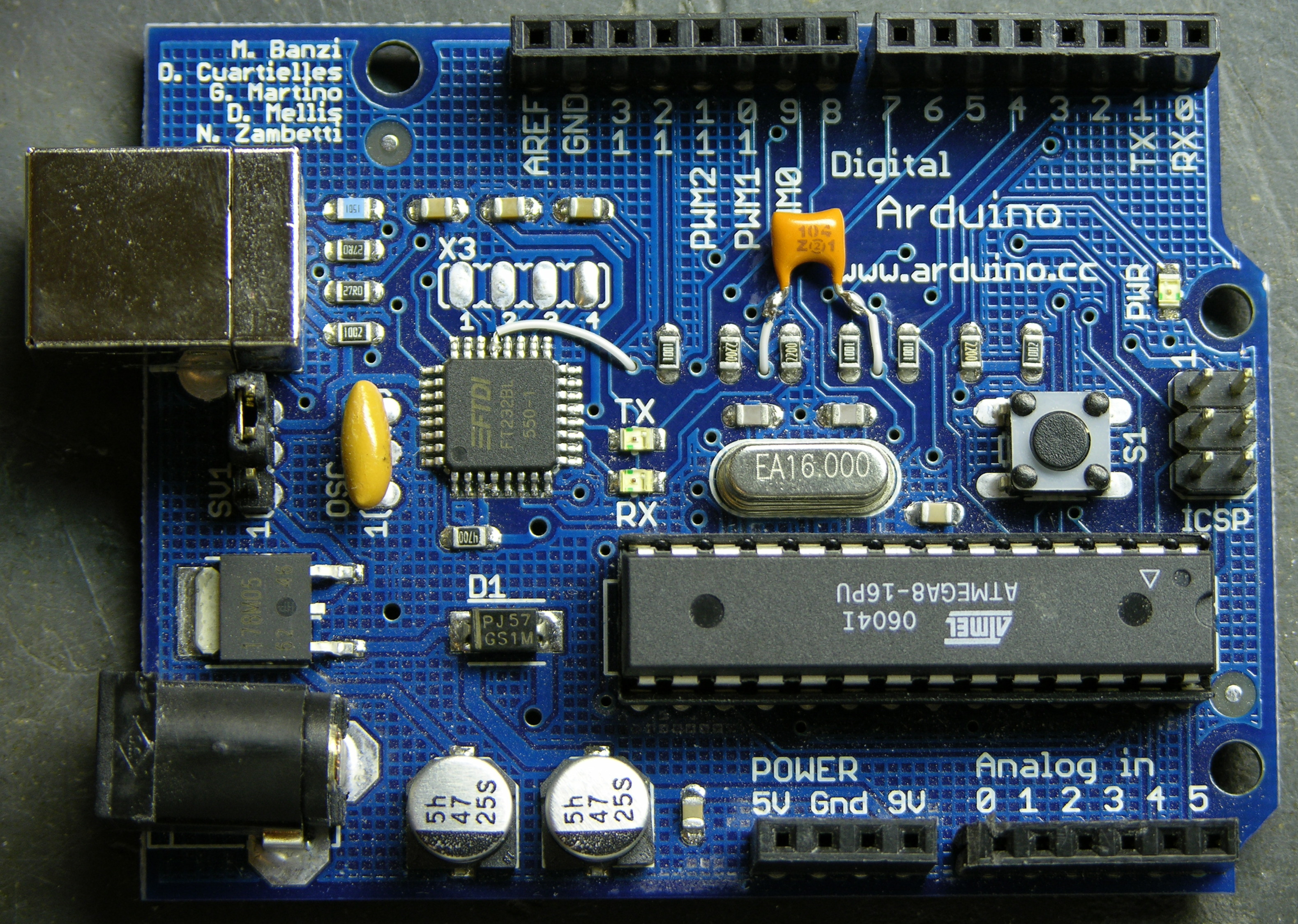
I got the datasheet for the FTDI FT232BL USB-serial chip, and for a moment got my hopes up higher than I should have. The DTR line is in the row toward the top of the Arduino board, and it looked as though it might already be broken out into the unpopulated, .1″-spacing X3 header. Nope, nope, it’s about the only line on that side that’s not already broken out. I was going to have to solder directly to the chip.

Given that it’s a 7mm-square LQFP with .8mm (.03″) lead spacing, I should perhaps have set it out with a thimbleful of Special Sheep Liniment to entice the Nac Mac Feegle to solder for me. But I have no dearth of hubris, and soldered it myself. Twice, in fact, the second time after cutting the other end of the wire too short to reach the capacitor.

top-side zoom

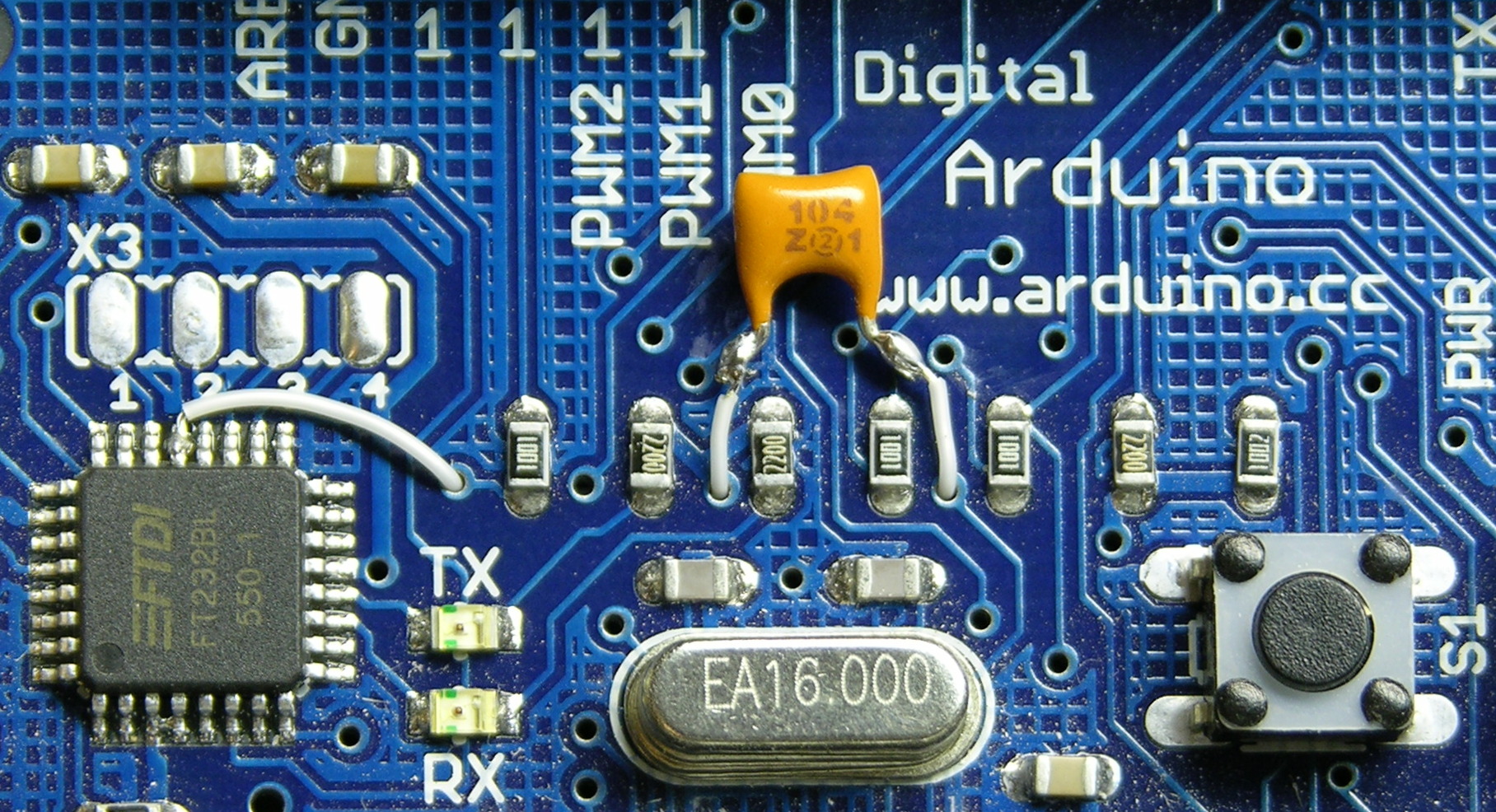
One side of the capacitor connects to the DTR line of the USB-serial chip, the fourth pin from the left on the upper edge. The other side connects to the reset line, which appears to be available only on the microprocessor, the ISP header, and the reset button. I chose the reset button on the underside of the board.

I could have used a capacitor with long leads, sleeved them, and connected them directly to the pins at both ends as in the serial board hack; but I thought it looked better to use wire-wrap wire.

bottom side

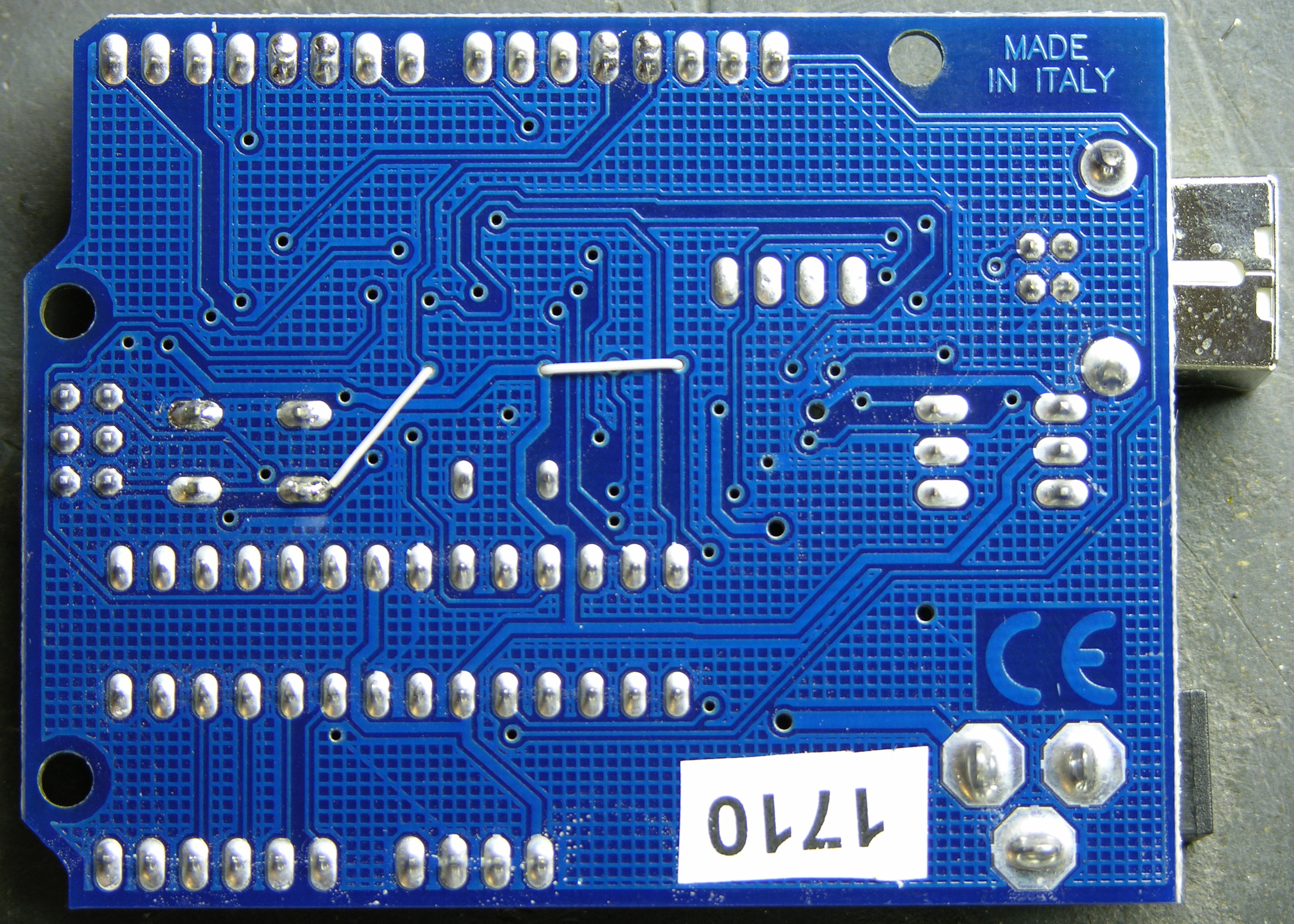
I laced the (insulated) wire-wrap wire through open vias in the board to keep things tidy and the capacitor snugged down. A few dots of glue would have done the same had I wanted to keep all the wires top-side, but this felt a little more artful to me. Plus it seemed easier to solder to the underside of the reset switch rather than the top, so I was feeding a wire to the back side of the board anyway.

IDE and Auto-Reset

I upgraded the integrated development environment to version 10, which adds the DTR-triggering, and tried it out. The host computer does indeed now reset the Arduino, and I can upload software to it without pressing the button! Hooray!

But there’s still about a 10-second delay after a boot, reset, or upload before the software starts running. Boooo!

Bootloader and USBtinyISP

One of the hacking guides suggested that the Arduino bootloader would need to be upgraded in order to reduce the reset delay, which makes sense. The IDE includes the ability to burn a new bootloader, for which the bootloader web page gives instructions. Burning the bootloader, unfortunately, can’t be done through the Arduino’s serial interface; it requires a separate AVR programmer.

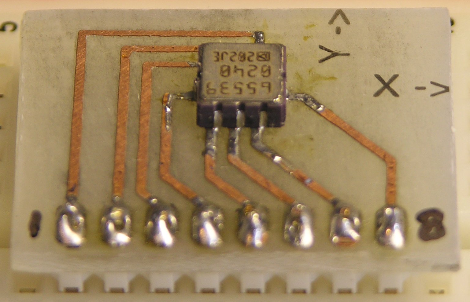
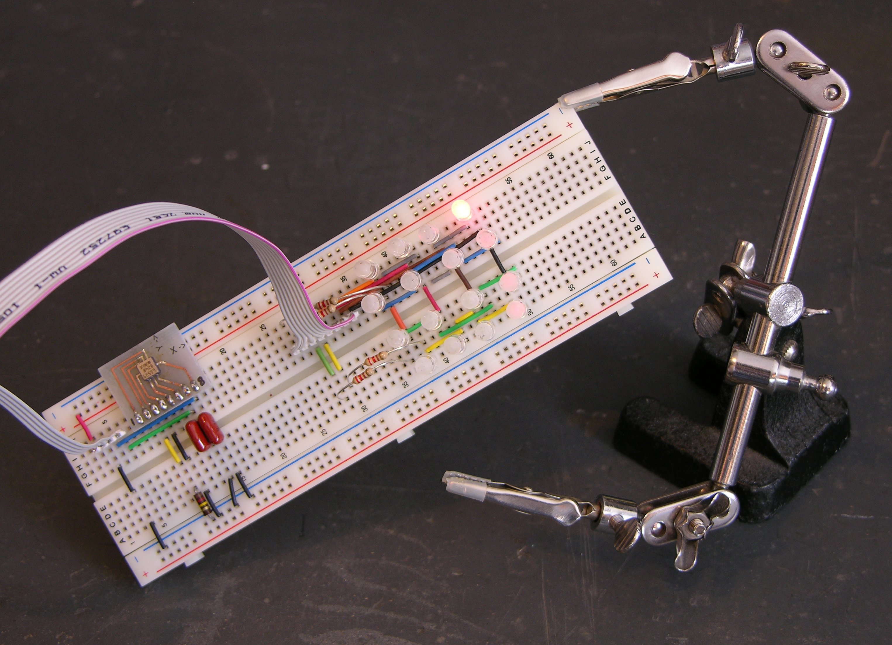
Thus it was time to assemble my USBtinyISP kit from LadyAda.

USBtinyISP PCB

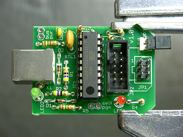
I bought it a while back in order to be prepared for programming ATmegas outside of the Arduino board. It’s an Atmel ATtiny chip interfacing directly between a USB connector and two cables for in-system programming. The board is nicely made, the instructions are clear enough for absolute beginners, and it was a joy to solder.

USBtinyISP

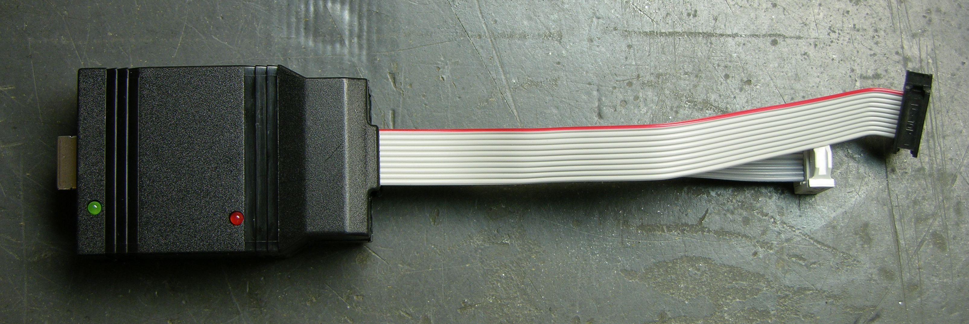
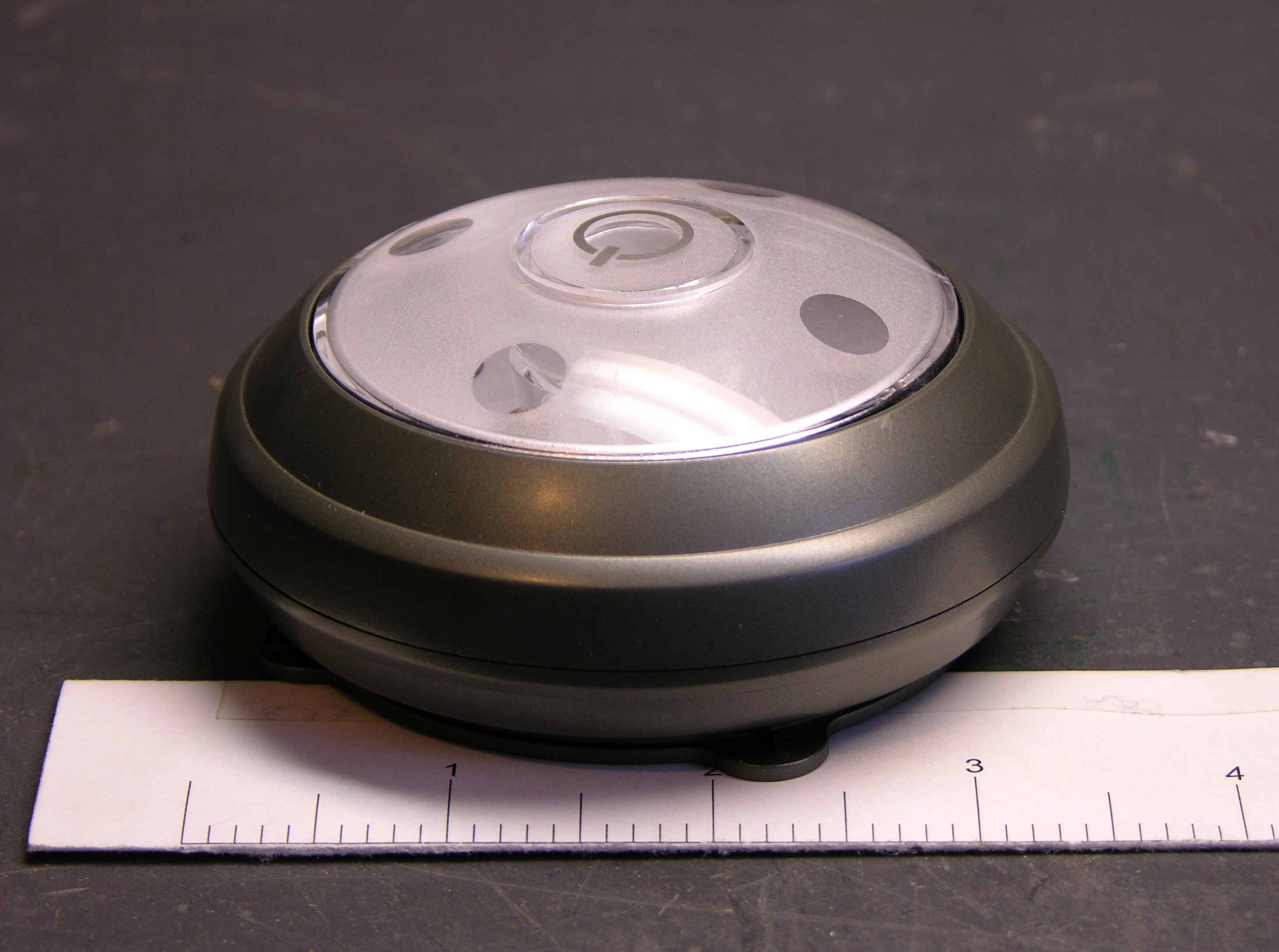
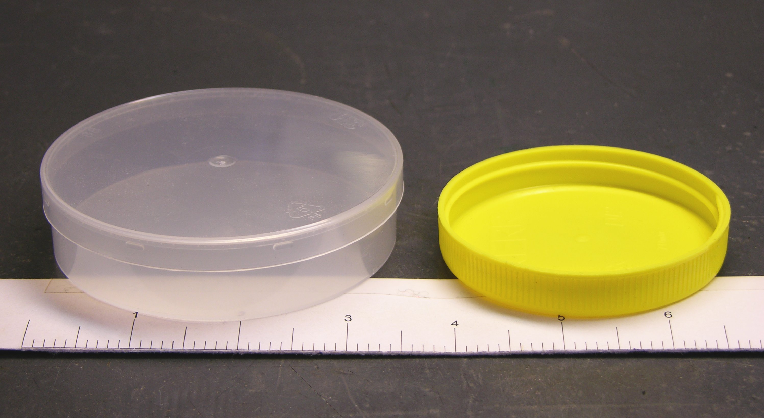
Fully assembled, it lives in a shell that makes me think of old serial line drivers; but the shell is somewhat customized to fit the USBtinyISP board (and vice-versa).

I read recently and have since forgotten the name of the little “columns” built into plastic enclosures (like toys) to hold PCBs in place; but no matter, since my point is that this case doesn’t have them. The USB end of the board had a lot of room to move and was a bit wibbly-wobbly, but I took the foam that the chip shipped in and packed it between the USB connector and the top of the case, which secured the whole thing nicely.


The term is mounting bosses, seen at Near Future Laboratory.


That done, I unplugged the Arduino’s USB connector, plugged the USBtinyISP into the Arduino’s ISP header and into my iBook’s USB, and burned a new bootloader. I went to the Arduino IDE’s Tools / Board menu and selected Arduino NG or older w/ ATmeta8, then Tools / Burn Bootloader / w/ USBtinyISP. The USBtinyISP’s programming light went on and IDE told me it was burning and would take a minute. Twiddle twiddle.

Finished. Disconnected the USBtinyISP and reconnected the Arduino. It didn’t seem to have my program on it any more, which I guess makes sense that doing low-level AVR programming would wipe the whole memory. I uploaded my code again; and when the upload finished, it took about 10 seconds to start the code. Hrm. Pressed reset, and it took about 10 seconds. HRM.

Arduino Bootloaders and ATmega8

My Arduino is so old that it has the ATmega8 instead of the ATmega168. I don’t know whether that’s true of all Arduino USB boards, but it’s certainly true of mine.

It would appear that the ATmega8 bootloader image has not been updated for the auto-reset. Poo.

The bootloader source code is available online, but the ATmega8 code looks unusable. By that I mean that large sections of code are commented out, including the part that makes timeout after n seconds. (Yes, I’m saying it appears that it would wait forever for a software upload before starting your program.)

It looks to me like it’s been half-***ed patched with updates that have been made to the ATmega168 bootloader, but that parts that would have taken any effort to fix have been commented out rather than updated. Yes, I’m bitter.


See the comment from David Mellis, a developer of the Arduino, below. The timeout value is still present; I just didn’t look carefully enough. The ATmega8 bootloader code probably is what’s in the IDE, and it should be possible to recompile it with a shorter timeout. I’ll provide a further update once I get that worked out.


Interestingly, the ATmega168 bootloader code includes conditional compilation for many different ATmega chips, including the ATmega8. It seems likely that I could build it for the ATmega8 and get it to work. However, the bootloader web page says that the ATmega8 bootloader is only 1k rather than the newer bootloader’s 2k, an important savings given the ATmega8′s mere 8k of FLASH.

Fix the abandoned ATmega8 bootloader code myself? Sacrifice an extra 1k of program space by using the newer bootloader? Sigh.

Another option would be to buy Lady Ada’s preprogrammed ATmeta168 microcontroller. Of course I’d check first, but I think the ATmega8 and ATmega168 are pin-compatible. If that’s the case, I could pop in a 168 (preprogrammed from her, or straight from the factory and program it myself with the USBtinyISP) and be done with this. But it really grates on me to replace hardware when a software fix is perfectly viable.

And of course I could just try lying to my IDE about what chip I have and burning the ATmega168 bootloader into my ATmega8. But looking at the source code, there are enough differences between the ATmega168 and ATmega8 sections that I’m leery of doing this. I wouldn’t mind if it simply didn’t work, but I don’t know enough to be sure it wouldn’t damage the chip somehow. I’d rather live with the delay (for now) than destroy the only chip I have (for now).

To Sum Up

The capacitor-reset hack was easily adapted to the Arduino USB, if you don’t mind a little fine-pitch soldering. Yay! That plus an upgrade to v10 of the Arduino IDE allow the host computer to reset the Arduino when uploading new software, relieving you of pressing the reset button each time. Yay! But I don’t yet have a solution to reduce the reset delay on a board using the ATmega8 microcontroller. Boo!

LED Puck: Tilt Prototype

Thursday, December 27th, 2007

My wife isn’t interested in electronics. She doesn’t do electronics, she doesn’t understand electronics, and she really doesn’t want to hear me ramble on at length about electronics. (I say this all in a very good-natured way, of course. Identical interests were not a prerequisite for our marriage.)

So when my wife asks my why I keep soldering chips onto boards in the wrong direction, I know I have a problem.

Oh, and the ADXL202 is a hardy little sucker.

Prototype Puck I/O Board

Over the weekend, I laid out and built a prototype of the I/O for the puck — just the LEDs, their driver, an accelerometer chip, and a pushbutton. I expect to use the Freeduino circuit for the microcontroller and will still need to add it to the board (as well as battery-charging circuit and all that other good stuff); but I wanted to get started programming the actual LEDs and tilt system.

LED puck I/O prototype PCB, cleaned and cut

I laid out the board in EAGLE; and believe me, it’s a bit of a challenge routing nice curves as traces. The V+ circle around the edge wasn’t too bad; but I wanted to route the LED drive traces as concentric arcs and just couldn’t find a way to do it.

I had a few SMT A6276 LED driver chips around, so I was able to make most of the board SMT already. The A6276 will want to be on the underside of the board (shown here) so its pins are in the same order as the LEDs it drives. I’m not sure where the other chips should be, but it was easy to make a single-sided board for this prototype.

I worried that I was packing the traces too closely together; but they came out well enough (iron-on toner transfer), I think I could have made them smaller. And having to run to headers to go off-board to the Arduino complicated the routing; if the microcontroller were on the other side of the board, each of those signals could have gone through on a via wherever it was convenient rather than having to converge to the two headers at the top and center.

Tinnit

I tried plating the board with Tinnit, because I had such good results last time — that board was incredibly easy to solder. Alas, five-month-old eighteen-year-old Tinnit apparently doesn’t work very well. After forty minutes at 110°F with no plating appearing on my traces at all, I gave up, washed the board clean, and dumped the rest of the Tinnit.

I still think it’s great stuff and I intend to use it again. I just need to be sure I’ll be making enough boards for it to be worthwhile.

I did learn something else, though. After cleaning the board, it sat out for a few hours, and I noticed that it was already oxidizing — the copper was considerably less shiny than when it was fresh. Before soldering, I polished it with wet 600-grit sandpaper, and it took solder beautifully — completely unlike untinned boards I’m used to soldering.

Lesson: If a copper board has been exposed to air for even a few hours, polish it with wet, fine sandpaper before soldering.

Assembly

I soldered on all the SMT components first. I was pleased that I was actually able to find all the resistors and capacitors I needed in my salvage bin. I’ve desoldered a number of SMT boards (heat with heat gun, then bang on the bench vise and the components come flying off; or pluck them off with tweezers for a more orderly approach), and I think these came from a dead Cabletron hub.

LED puck I/O prototype, SMT components soldered

The resistors were all labeled, so they were easy to search for the right values (if you call picking through a bag of grains of rice easy). The capacitors were a bit more challenging — they were completely unlabelled, so I had to dump them out on the workbench and use the meter (tweezer-style) to find the values I needed.

LED puck I/O prototype, copper side

I placed all the LEDs with their cathodes facing clockwise (as viewed from the top) for simplicity — so I wouldn’t have to think about which way each one goes. Although parts of the puck are obviously asymmetric, I prefer to think of the puck as a whole having at least rotational symmetry, and I wanted the LED orientation to reflect that as well.

LED puck I/O prototype, LED side

The jumper wires are a bit scabby, particularly the one running halfway across the board at an odd angle; but again, they’re at least partly due to routing challenges with not yet having the microcontroller on board, as I mentioned earlier.

I should stop to add that laying out an SMT board is really refreshing, in that you can fill both sides of the board with components and traces, and not worry about through-holes impacting the routing on the other side of the board. As long as you don’t need to hop to the other side and back to cross one trace over another, each side can be completely independent of the other.

That’s not illustrated well by my single-sided SMT board; but I mention it because I’m really looking forward to laying out the microcontroller (probably on the top side) and cleaning up some of these traces and jumpers.

Two Mistakes on the Accelerometer

First: absent-mindedly running the resistor that sets the PWM output period to the self-test pin by mistake. Second: soldering the accelerometer to the board 180° from its proper orientation.

When I first powered up the board, I was most interested in testing the LED driver, since I had already tested the accelerometer on the breadboard. The lights didn’t come up (I had forgotten to manipulate the output enable line in my program), but I also smelled hot electronics. I fixed the program, the LEDs worked, the accelerometer didn’t, and I realized my mistake.

On the EAGLE PCB layout, I had a marking for the accelerometer orientation, of course. But the marking was on the silkscreen layer, and I didn’t make a silkscreen layer when I etched the board at home. Then because the components are on the bottom side, I got myself confused about which end of the accelerometer was which.

Lesson: Copy IC orientation markings to the copper layer for homebrew boards.

Rework

Last night I waved my soldering wand and cast a spell of devious reparo on the accelerometer chip; but apparently it backfired, because it ended up looking like this.

Closeup of LCC and stacked SMT capacitors

I actually used solder wick to remove the errant PWM period resistor — it did a nice job of sucking up solder, heating both ends at the same time, and then scooting the resistor off its pads so it wouldn’t stick back down when the solder cooled.

I used solder wick to suck up all the solder I could from around the accelerometer; but I didn’t have a way to heat the whole thing at once, so I couldn’t scoot it away. I need a hot-air pencil and looked at several DIY designs, but didn’t want to take the time out to build one. There was little enough solder left, I was able to twist the chip off the board with a pair of pliers.

I lost a couple of pads in the process; but when I soldered it back down, one was NC and the other I was able to bridge with solder. Then I needed to move one of the resistor traces from the left pin to the middle . . . and the easiest way to do it was to solder one end of the resistor directly to the chip.

Yes, I’ll fix it right in EAGLE for the next board.

BTW, notice the stacked SMT capacitors on the right. I couldn’t find anything in the .1uF – .2uF range in my bag, so I paralleled a couple of 75nF. Nasty!!! :-)

Proto-Puck

The upshot of all this, if I can finally get to the point, is that I have a working proto-puck.

Arduino and puck

I have ribbon cables connecting it to the Arduino for power, LED output, and tilt input. The LED driver works perfectly, and (miraculously) the accelerometer works now that I’ve reoriented it. And that means I’ve been able to start writing code.

This isn’t much yet — it only detects whether the tilt is inner or outer, and which quadrant it’s in — but I think it gives a flavor of things to come.

Project Idea: Household Pager

Sunday, December 23rd, 2007

When we’re doing several other things at the same time as baking, it’s easy to forget to check the oven, and things get burned. When we’re watching a movie and the phone rings, it’s annoying to have to go to the phone to check the caller ID to see whether it’s worth interrupting for.

I want a household pager that vibrates and has a single-line alpha display. Range limited to my house, and integrated with everything.

Set the oven timer; when it goes off, the pager says “Oven timer.”

Incoming phone call, pager shows the caller ID. Doorbell could show “Doorbell,” in case we were upstairs where we can’t hear it.

Washing machine, dryer, or dishwasher finishes running, pager lets you know.

Integrated with everything in the house, I think it could be incredibly handy. Sensor modules could be serial-numbered, so you assign text to functions in the base station rather than at each sensor. Of course, the trick is integrating with everything in the house.

LED Puck: Tilt Video

Friday, December 21st, 2007

Many thanks to John Harrison for showing me how easy iMovie is to use.

YouTube must by default pick the middle frame of the whole video for the thumbnail screen? I’ve updated it to use a different frame, but they say it can take six hours to take effect. Meanwhile, here’s a great video apparently about hysteresis!

YouTube has synced my change for which frame gets used for the video still, so the joke about the hysteresis video doesn’t work any more.

LED Puck: Need an Inexpensive Accelerometer

Wednesday, December 19th, 2007

I thought I’d seen an accelerometer chip recently that retailed for $3-5, but the cheapest I can find on Digi-Key is $7-9. I’m really worried about the puck price climbing out of control. Anyone know of cheap accelerometers?

LED Puck: Concept Drawing

Tuesday, December 18th, 2007

LED puck concept drawing

Hm.

(Click above for unsquished version. Well, unsquished graphic. The design is still too squished.)

LED Puck: Parts List Draft

Monday, December 17th, 2007

If I don’t make a list of everything I need to get, I’ll end up waiting on a parts order before I can finish a prototype, or worse, leaving something off the design entirely.

ICs:

  • Atmel Atmega8 or Atmega168 for Arduino/Freeduino
  • USB interface chip?
    maybe only if USB is going to be externally accessible; could use LadyAda’s FTDI USB cable if willing to get inside to reprogram
  • voltage boost / regulator
  • battery charging controller
    maybe LM3622 used in the WaveBubble
  • Allegro A6276 16-bit LED driver
  • digital resistor for LED current reference and dimming?
    or could PWM A6276′s enable line — I probably like the PWM idea better
  • accelerometer / tilt sensor
    sample the cheapest one I can find and make sure it’ll work — probably a thermal
  • Dallas RTC
  • temperature-compensated crystal oscillator for RTC
  • *PROM for fonts for POV mode?
  • EEPROM for saving configs and POV text?
  • LM34 Fahrenheit temperature sensor?

Other:

  • ultrabright 5mm LEDs with > 30° viewing angle (15° half-angle) and prefer > 10,000 mcd
  • very slim high-energy-density battery
    16 LEDs * 25mA/LED = 400mA, so well over 400mAh for an hour of runtime at full brightness
  • coin cell and holder for RTC chip and oscillator
  • watertight mini-USB connector for tethered charging and reprogramming???
  • photoresistor or LED for light detection (maybe several around the edge?)

I’ve kind of dropped connectors for remote wired control, and wireless for a keyfob control. How much do those matter?

Project Idea: Solar Sidewalk Melter

Sunday, December 16th, 2007

Our driveway is on the northwest side of our house, and the sidewalk beside it stays shaded and icy even when the front walk has melted dry.

Put a 2′ diameter mirror on the west edge of the roof to reflect sunlight down onto the sidewalk, with servos to aim. Photosensors could detect whether the sky was clear enough to be worth tracking the sun, or it could just do it anyway. Sweep back and forth along the length of the sidewalk on a one-hour period, to melt and dry the whole thing evenly.

It could use solar declination and time of day to calculate aim totally open-loop, or use photovore behavior to track the sun and then calculate the appropriate angle to aim at the sidewalk, or put sensors beside the walk to run as a remote photovore, or put a camera by the mirror and watch where the bright spot is. Or recognize that I only need it to work in the winter, assume a known solar declination, and write a fixed program for solar tracking and sidewalk sweeping.

Two addenda:

I’m talking about a flat mirror, not a solar death ray. One sunlight is enough to clear the front walk; that’s all I want to add to the driveway walk.

I’m not a mechanical engineer and I can’t quite picture it, but it seems to me that it might be possible to make one motorized photovore to track the sun, one motorized sweeper to move a pointer back and forth aimed at the sidewalk, and attach the mirror to a geared angle-splitter that bisects the angle between the two.

LED Puck: Tilt Menu Demo

Sunday, December 16th, 2007

I have a working prototype of the tilt menu system for the LED puck, albeit square instead of round, and missing the select button.

It started a couple of weekends ago at Cort’s house, where we made some breakout boards for two Analog Devices ADXL202 MEMS accelerometers I have. Sparkfun used to have a great-looking breakout board for them, but it had the filter capacitors on board and I really wanted them off-board for easier prototyping and testing different signal bandwidths.

ADXL202 breakout board, etched

We did iron-on toner transfer etch resist, using Cort’s heat press. We also did toner transfer for the silkscreen-layer labels.

ADXL202 breakout boards

The boards came out very nicely, although the straightness of my hacksaw job leaves something to be desired. Besides indicating the positive directions of the X and Y axes, the silkscreen layer also had labels for the individual header pins; but they didn’t stick at all well going up and down the edges of the copper traces, so I scraped ‘em off. Ditto the pin-1 indicator for the LCC chip.

ADXL202 breakout board, top view

Here’s the board I’ve assembled, with header pins hand-labelled.

ADXL202 breakout board, LCC soldering

I used the Sparkfun SMT soldering method — slop solder on and wick off as much as you can. It leaves enough between the chip and the traces to make good contact, while eliminating solder bridges.

This was a bit interesting to position while soldering. Because it’s an accelerometer / tilt-sensing chip, I wanted its orientation as closely aligned as possible with the orientation of the carrier board. Absolute position doesn’t matter; but if it were rotated relative to the board, its readings wouldn’t align with the tilt of the project it was part of.

I knew I wanted to hold it securely in place while soldering, rather than tacking down a corner and hoping it was rotated about right while soldering the remaining pins. I thought about using a hemostat, but Cort’s was way too strong and would have crushed the chip. I ended up using a needlenose vise-grip, backing it off far enough to just barely grip the chip. I still worried about crushing it; but I was careful enough, as the accelerometer still works.

Tilt Menu Software and Prototype

The whole idea of tilt-menu-based control comes from reader Kevin Reid‘s suggestion:

Accelerometer-based control!

1. Press single control button.
2. Tilt puck such that the LED indicating the relevant function is lit.
3. Release button.

I don’t know whether that’s the exact mechanism (press/release) I’d like to use, but I love the overall idea. To clarify one point, the top of the puck will be rounded/domed, so tilting the puck will light the LED that’s “on top,” like an air bubble floating inside a liquid-filled dome.

With the accelerometer breakout board completed, I was able to prototype the system.

Tilt menu prototype

The Arduino at the bottom is the brains. The accelerometer is at the left end of the breadboard with fairly large signal-filtering capacitors — I sized them for about 50 discrete readings per second, which I think should be more than enough (and is still far fewer than the device is capable of). Note that I’m using the accelerometer’s analog outputs and the Arduino’s A/D inputs; I didn’t feel like measuring pulse length from the ADXL’s digital outputs.

The LED matrix at the right end of the breadboard is kind of ugly, at least to implement on a breadboard (as well as hard to see in this picture). I intend to use an Allegro MicroSystems A6276 16-bit serial-in, parallel-out, constant-current LED driver for the real thing . . . but I can’t find where I put mine, so I just hacked together a row/column drive straight out of the Arduino.

The Arduino code is nothing special, but here it is:

tilt_menu_demo.pde

It reads the analog inputs to get the X/Y tilt, translates from the scale of the A/D converters into the size of the LED matrix, and drives the row/column outputs. I added hysteresis that (although simple) does a fantastic job of keeping the LEDs from flicking back and forth when you’re on the fence between two adjacent ones. And I used tristating on the LED matrix drive because it made more sense to me to float unused lines than to flip them to the opposite value.

Tilt menu demo, flat

Here’s what it looks like sitting on a flat surface. One of the four center LEDs is lit — it turns out to be always the same one, as I haven’t calibrated the accelerometer readings for perfect level yet and it lists a bit to one corner. Note that one of the envisioned modes for the puck is a bubble level; and in that mode, I think I’d flash the four center LEDs to indicate when the puck is perfectly level.

Tilt menu demo, upper right

Tilted a little bit, a different LED is “uppermost” and lights.

Tilt menu demo, far upper right

Tilted dramatically, the corner LED is “uppermost” and lights. Note that the amount of tilt required is set by the TILT_MIN and TILT_MAX values, so it’s easily adjustable for dome shape and/or user preference.

Not Really a Square Matrix

I indicated early on that I pictured LEDs around the perimeter of the puck angled slightly out for good dispersion, so the square matrix I made this weekend was just for a quick demo. I’m actually thinking of twelve LEDs around the perimeter (analog clock mode!) and four in a square surrounding the center, totalling the 16-LED capacity of the A6276 driver chip. I’m working up some very simple drawings of what it might look like, which I hope to post soon.

LED Puck: Comparison Shopping and Assignment

Saturday, December 15th, 2007

Maeve had several of these battery-operated, white LED accent lights, and let me borrow one until the next visit.

Commercial LED puck

It was a good opportunity to test a few ideas about the LED puck. If a commercial product was already on the market, albeit for a different target audience, maybe it’d be good enough and I wouldn’t need to design my own. More likely, I could identify and clarify design differences between their product and my own ideas, which is what turned out to be the case.

First, the LEDs in the commercial puck are pretty directional. When placed on a nightstand pointing at the ceiling, it illuminates about a 2′ diameter area. I’d like the puck to be much more omnidirectional, casting light as evenly as possible throughout a hemispherical area.

Second, it’s not bright enough. Used like a flashlight and pointed directly at a book, it provides more than enough light to read; but pointed upward, the diffusely reflected light isn’t quite enough to read by. I specifically want to be able to read by the light of the puck, and I’d need several more LEDs and somewhat more power to be able to do that.

Third, it’s too bulky, specifically, too thick. I could never carry it in a pocket. I have been carrying it back and forth to work in my laptop satchel, but I realize I’d like the puck (or one version of it) to be small enough to carry with me in a pocket all the time. What’s the point of having cool toys if they’re never with you when you need them?

Commercial LED puck, tilted

The light portion of the commercial puck tilts so it can be aimed, and the light portion is actually plenty small to carry around in a pocket. The whole enclosure is larger both to accommodate the tilting action, and because it houses three AAA cells.

The space needed to accommodate a power source concerns me. I’d like to find a flatpack LiPo battery, skinny like a cell phone battery; but I fear that power may be the driving constraint on overall puck size.

Homework Assignment

For anyone reading who’d like to build their own puck, or anyone amused enough by the idea to humor me, I have a homework assignment for you.

Find something round, (*) about the size that you envision the puck being, and carry it with you for a few days. Post a comment about what you used, its dimensions, where on your person you carried it, how comfortable/convenient it was, and whether you’d carry something that size with you all the time.

* (I envision the puck having a rounded profile like a drop of liquid sitting on a horizontal surface, rather than being an untrimmed cylinder. Rounding off the top would slightly improve the comfort of carrying it in a pocket, but cylinders that I’m able to find are good enough for a first test.)

Electrical tape container and peanut butter jar lid

I’ll start:

  • I’ve been carrying the commercial LED light in my laptop bag for a week. It’s 3 1/2″ d and just over 1 1/2″ thick. It’s way too thick to fit into a pants pocket; it fits fine in my laptop bag, but then so would a hardback book. I would always have it nearby, although never on my person.
  • My first inspiration for the physical form factor of the puck was the empty container from a roll of 3M electrical tape. It’s also 3 1/2″ d but only .9″ thick. It’s still the size that I think would look best for a puck, but it’s uncomfortably large to carry in a pocket, and I haven’t even tried. I would definitely carry it with me in my bag.
  • The peanut butter jar lid is 3″ d and 1/2″ thick. I’ve been carrying it in my back jeans pocket since last night, and I hardly notice it’s there; I’d notice it even a little less if the top edge were rounded. This would be a great size for carrying with me all the time — but there’s no way to fit both battery and outward-angled 5mm LEDs into that thickness.

Maybe two puck sizes will be needed — the original puck, in the electrical tape container size, and the porta-puck, in the jar lid size.