Archive for August, 2007

Elastomeric Connectors

Tuesday, August 28th, 2007

A reader named Dave posted a very well-informed comment that what I’ve been referring to as an anisotropic strip (connecting an LCD to a PCB) is more specifically called an elastomeric connector. I thought it was interesting enough to be worth pulling up into a new post:

The anisotropic strip on the LCD is technically known as an elastromeric connector, but usually referred to as a zebra strip. If you examine it closely under a strong magnifying glass or a low power microscope, you’ll see alternating bands of conductive and insulating material, usually something like graphite loaded rubber for the conductive material and unloaded rubber for the insulating material. The graphite loaded rubber gives that portion of the strip a darker colour. Thus, you have alternating light and dark bands, similar to what a zebra looks like. :-)

Dave

Thanks for the detail!

Welcome, Make Readers!

Wednesday, August 22nd, 2007

Wednesday afternoon:

I never expected this kind of web traffic to my blog, and my current image hosting solution isn’t up to the job.

I’m mirroring right now; images should be back up within a couple of hours.

Wednesday evening:

Images for recent posts should be back up. The remaining images from 2007 are almost done mirroring to the new server, and earlier images will get mirrored if there’s still time while traffic load is still high.

Thursday morning:

Everything seems to be mirrored and working!

Letting the Smoke out of an A3977

Wednesday, August 22nd, 2007

A3977 stepper motor driver breakout boards

What’s the difference between these two boards?

  • The one on the right is prettier.
  • The one on the left has the driver chip soldered in the correct orientation.
  • The one on the left still has the magic smoke.

Tinnit

Monday, August 20th, 2007

Tinnit is a tin-plating solution for coating copper PC boards. It dissolves in water and plates boards without electricity (which standard electroplating requires). The silvery coating prevents the copper from oxidizing, and also takes solder more easily than even clean, bare copper.

I’ve had an unopened package in my PCB-making kit for about eighteen years now. The problem is, once mixed, it has only a six-month shelf life, and I’ve never expected to make enough boards within six months to be worth using up the package.

Yesterday I finally took the plunge, and I’m rather impressed. Everything I did all day worked out pretty well . . . so let me get to the Tinnit in my usual roundabout way. :-)

Stepper Driver on 24-30V

I borrowed a DC power supply from the class lab to test my stepper driver on 24V and 30V load supply. I had got up to 2300 steps per second on 18V, and I hit 2700 steps per second at 24V and ran out of speed on my controller. I’m not using the Arduino’s PWM outputs yet, and 2700 steps / second seems to be about as fast as my program goes using software-based stepping.

I’ve been running the motor in half-step mode because it’s noticeably smoother, at least at lower speeds. But that also means I only get half the motion for each step signal I send. For the sake of testing top speed, I rejumpered the driver board for full-stepping and tried again.

The motor was immediately jerky and twitchy, like it had been with inductive sense resistors. Not only was the top speed drastically lower, but it took great care to ramp up to the top attainable speed. I jumpered back to half-stepping — and the problem didn’t go away. I checked all my connections, measured parts of the circuit, swapped the motor, put a scope on the sense resistor terminals — no go.

I broke it. Still don’t know how.

I’d been planning to build another driver board soon anyway, to drive a second axis prototype. With my first board misbehaving, I could also use the second board to help troubleshoot the first.

I also had a list of changes to make — things that were inconvenient about my first A3977 breakout board. I updated my layout Saturday with (among other things) nice jumpers for option settings, better grouping of signal inputs and outputs, and less reliance on having to solder leads on both top and bottom sides to carry signals through unplated vias.

Hand-Drilling and Etching the PCB

PC board stock, copper pattern, and center punch

Normally I’d use Joel’s CNC machine to drill my board, but the timing didn’t work out this weekend. Instead, to prepare for hand-drilling, I taped together two sheets of my thin double-sided board stock with a printout of the top-side copper pattern and used a center punch to mark the holes.

Alas, I was a bit overzealous with the center punch.

PC boards, holes overpunched

The dimples went through both boards in the stack. Yeah, thin board stock.

I drilled the holes carefully with a #71 bit, then used a hammer to flatten the dimples on the anvil surface of my bench vise. Apparently I did a good enough job, because I made a nearly flawless two-sided iron-on transfer on glossy paper (not even bothering with Press ‘n’ Peel Blue), using the paper towel between the iron and the board again to distribute the pressure.

Etched PC board

The board came out as nicely as any I’ve done. I used 16 mil traces and 40 mil isolation, so it wasn’t particularly challenging. Still, it etched very cleanly.

Etched PC board with pockmarks

I did have a little trouble with pockmarks in some of the large copper areas. They don’t impact the performance — just the appearance. I could perhaps have sanded and polished the board to make it prettier; maybe next time.

Tinnit

On each of the last two PC boards I made, after partially populating the board, I really wished I had tried using the Tinnit. And I’m making more boards now — I know I’ll make at least one more stepper driver board (for the third axis), and probably lots of other things, in the next six months. So it seemed like a good time to try it.

The instructions say to mix the Tinnit powder package with 12 oz of hot water, then add enough water to make a pint. To plate a board, heat the solution to 120-140°F in a pyrex container, then dunk the board for 35-40 minutes, agitating every five. Store the leftover solution in a metal-free container.

Well, my package had two smaller powder packets in it, and it wasn’t clear whether that was two doses or two parts of a single dose. Nor could I find any help online. I took a chance and poured in both packets; and when the second packet caused it to start foaming, it was clear that they weren’t the same and both packets were in fact required.

Tinnit solution in glass jar

I mixed the solution in a glass candy jar that I got from a vendor about eight years ago. The jar was just big enough to dunk yesterday’s PC board, so I sidestepped a search for an appropriate separate pyrex container for heating the solution. I put the whole jar (minus the lid) onto a stove burner turned to low and checked the temperature and stirred frequently (with a plastic spoon). It’s not obvious from this picture, but there’s a flaky white precipitate at the bottom of the jar that only went fully into solution at about 130°F.

Tinned PC board

The board started turning silvery almost immediately, and coverage didn’t change visibly from about ten minutes in solution until forty minutes when I took it out. I washed and scrubbed it pretty thoroughly, and it still smells like salts.

The result is very shiny and silvery. The pockmarks are still visible — Tinnit (and electroplating in general) doesn’t cover to enough depth to smooth a rough surface — but the board looks pretty good.

PLCC soldered to board

I’m particularly impressed by how much of a difference it makes in soldering. I know it’s easier to solder tinned components, but clean copper takes solder reasonably well. Still, this was amazingly easier to solder. When I built my first A3977 breakout board, I was flowing solder across multiple PLCC leads and cleaning up solder bridges; last night, I was able to solder individual leads with my SMT soldering tip.

PC board with monochromatic components

As I was stuffing jumpers and headers, I noticed how monochromatic the board was without the resistors and capacitors installed yet. I finished all the black, silver, and white components and stopped for the evening. Tonight I expect to add the passives and hopefully get the board up and running.

A3977 Stepper Driver and Higher Load Supply Voltage

Wednesday, August 15th, 2007

According to the explanation in my previous post, the Allegro A3977 stepper motor driver should be able to run motors faster with a higher load supply voltage. Naturally, I was eager to see this for myself.

Yes, yes it does.

Throwing Together an Unregulated 18V Power Supply

I’d been using my benchtop PC power supply for both 5V logic and 12V load supplies. After swapping the sense resistors this weekend and improving my step rate from 600 steps per second to about 1450, I was really curious how much of an additional improvement I’d get from a higher load supply. The 3977 is rated for a 35V load supply, but some forum posters recommend going no higher than 30V, so I was looking to try out 18-24V.

Joel just dismantled a photocopier with 20V motors; but after looking at the power supply boards, it wasn’t obvious which of the several power supplies was the one providing 20V. Plus they were switching supplies, and I don’t know whether they had integral loads or whether I’d have to provide a minimum load externally . . . bluck.

So I hacked together my own ~18V supply.

18VDC 3A unregulated power supply

From left to middle to top, that’s a brand new Radio Shack 12.6V 3A transformer, 4A bridge rectifier from a dead PC power supply, and a 18000μF capacitor out of a workhorse Accel printer from a former employer. The line cord is from a broken coffee grinder, the five-pin socket came with the capacitor and the plug from Slim, and the remaining wires and connector are from the PC power supply.

Side note: I’ve seen a few big capacitors in my day, but these impress me. When servicing these printers, I once vaporized a chunk out of my pocketknife’s screwdriver blade when I discharged the big capacitor by accident. I know personally that the last time this capacitor’s printer was powered on was no more recent than 1998. On a lark, after getting the capacitor out of the printer, I put a voltmeter across it, and it still had 3V on it. Ran an LED for a couple of minutes while I was draining it. I screwed a 1KΩ resistor across it to drain it a little faster in my power supply, so I don’t have to worry as much about hurting myself.

Power Supply Calculations

I have never kept the formulas for different rectifiers in my head, so I’ll run through the numbers for this one here. The transformer’s secondary (V2) is 12.6VAC RMS, and the peak voltage of a sine wave is RMS * √2, so the secondary peak voltage (VP2) is

VP2 = V2 * √2 = 12.6V * √2 ≈ 17.8VDC

The peak DC output of a bridge rectifier (VP) is the peak secondary voltage minus the two diode drops, so

VP = VP2 – 1.4V = 17.8V – 1.4V = 16.4V

The output of a capacitor input filter is the same as the peak DC value of its input, minus load-dependent ripple, so I should be getting about 16.4VDC out of this setup. Measured about 17.1, so I’m in range. The transformer is rated for 12.6VAC output at 3A, so it’s almost certainly putting out a little higher voltage with such a light load. If I weren’t so lazy, I’d go measure it, but that’s out of the question. :-)

And there’s no regulator. Linear regulators convert electricity into heat, and I need neither less electricity nor more heat. The A3977 is effectively a switchmode regulator for the motor coils anyway; so by regulating its input load supply voltage too carefully, I’d just be duplicating effort. Especially for a test. Note that I’m still running the logic supply voltage from the well-regulated 5.0V output of my PC power supply — the red and black wires in the photo above are picking that up and adding it into the four-pin supply jack.

With my scope across the capacitor terminals, I estimated .2V peak-to-peak ripple when running one motor at full speed. That’s pretty lousy ripple for most digital or analog circuits, but by all appearances just fine for this application. Especially, as I intend to keep pointing out, for a test. :-)

And Yes, the Motor Runs Faster

The motor is running noticeably faster before losing steps — up from 1450 steps per second to about 2300 steps per second. That’s an improvement from 2.8 seconds per inch of linear travel to 1.7 seconds per inch — a considerable difference for something as simple as changing the load supply voltage.

I want more, of course. I still want to see what happens at 24V and at 30V, so I bought a bargain 24V power supply on eBay today. When it gets here, I’ll give it a shot.

It’s worth noting that as far as I can tell, I don’t need to change anything in the A3977 circuit to adapt to the new load supply voltage. The sense resistors determine the maximum current that should flow through the motors, and the whole job of the 3977 is to keep that the same regardless of supply voltage. And I provide VREF from a divider on the logic supply voltage, so that’s also independent of load supply. Slick.

A3977 Stepper Driver REQUIRES Non-Inductive Sense Resistors

Monday, August 13th, 2007

The stepper motors I’m using to build my CNC machine are rated for 2.5A. Now, when they’re holding one position, it’s easy to deliver 2.5A of current. But when the motors are rotating, their coils are being energized one at a time in sequence.

The coils are inductive, and inductors resist changes to current. So when a coil is first energized, it takes a moment for the current to build up to capacity. As a result, with a simple stepper driver, the faster you turn the motor, the less of the time each coil gets full current, and the weaker the motor gets.

The Allegro Microsystems A3977 stepper driver chip I’m using to control my stepper motors overcomes this by running at a (much) higher supply voltage than needed to deliver 2.5A, and by using sense resistors in series with the motor coils. When it’s time to energize a coil, the A3977 delivers the full supply voltage and watches the sense resistor. When the desired amount of current is flowing through the resistor (hence the motor coil), the A3977 shuts off the voltage (briefly), then ramps it up again. The result is the delivery of the desired current on average, but with a much more rapid start due to the higher supply voltage.

Buried within Allegro’s A3977 FAQ is the recommendation that the sense resistors should be non-inductive. Since the values required are the sub-ohm range, commonly-available resistors are in big sand packages — and as noted by Jeff Mann in a comment posted about my control board, are internally wirewound and inductive.

Sand resistors and non-inductive sense resistors

I had already bought Ohmite non-inductive sense resistors from DigiKey, which are also much smaller and more manageable than the big sand resistors. (The cross-section of the sand resistors is about 1/2″ square.) I hadn’t worked on the stepper driver in quite a while, though, and I hadn’t put in the noninductive resistors yet.

Did that Saturday. The difference in performance is amazing.

Performance Gains

The last time I did a speed test of my stepper motor controller, I was able to get about 500-600 steps per second before the motor started losing steps and stopped turning. Additionally, it growled and twitched when it was idle, and grunted and jerked at low speeds, smoothing out only at higher speeds.

A3977 stepper control board

With the non-inductive resistors installed, all the growling and twitching went away. (Someone should look at non-inductive resistors for bulldogs, but I digress.) I’m able to ramp the motor up smoothly from a stop to full speed.

And full speed has increased from about 600 steps per second to over 1450 steps per second, just from installing non-inductive sense resistors. With my 200 step/revolution motors and 20 tpi all-thread, that’s an improvement from about seven seconds per inch of linear travel to about three seconds per inch.

That’s still running on 12V out of my spare PC power supply, and I’m trying to rustle up a 24V supply to test with, which should increase the speed further. That’s also without tweaking the A3977′s component values — I hear there are some tricks to play there, too.

Executive summary:

Inductive sense resistors with the A3977 make the motor growl and jerk when idle and at low speeds, and limit maximum speed. Non-inductive sense resistors with the A3977 make the motor smooth and quiet at all operational speeds, and dramatically increase maximum speed.

Z Axis Completely Assembled

frame

I have the drill sled mounted in the frame, the motor properly mounted, and the joystick controlling it at variable speed. Next step is building the Y axis around the Z frame.

Credit Where Due

Many thanks to Jeff Mann for his original comment, which drew my attention back to replacing the sense resistors, and for our followup conversation, which helped me understand and think through how the PWM driver makes the motors work better at higher voltage without going over the rated current.

Rewiring a Game Controller’s Joysticks

Monday, August 13th, 2007

When the CNC machine is finished, it will of course be controlled by a computer. But during development, it’ll be handy to test it with other controls, like joysticks. I had in mind to use analog joysticks, so I could control motor speed as well as direction.

Unfortunately, I couldn’t find the analog joystick element that I bought from All Electronics. (That this happened something like nineteen years ago may have a little to do with why I can’t find it right now.) Fortunately, a poll of my friends for an analog joystick I could borrow yielded this game controller that Jeremy had already brought me in a batch of electronics junk:

USB game controller

In his own words:

Didn’t like it because it was crappy. The retractable cord (while an OK idea) was too short and stiff. Its real downfall was that the buttons were sticky. They wouldn’t pop back up immediately when pressed so rapid tapping was impossible. More frustrating than useful.

So, perfect for me to butcher for my own purposes.

Inside the Game Controller

My first thought was to extract the analog joystick elements, so I opened the case and dug in.

Game controller with case open

Here you can see all the guts that make it work. The upper half of the picture is the bottom side of the case, with the retractable USB cable recessed under the PCB, and wipers on the PCB to make contact as it spins.

In the handles near the bottom of the picture are small motors with eccentric weights for “force feedback,” and directly above them at the center of the picture are the pushbuttons on the forward edge. The tan PCB has contacts for the pushbuttons, LEDs, and pseudo-joysticks on the top face; and the green PCB is the brains of the outfit.

Game controller, main board

The main board holds the analog joysticks (the solder pads surrounding the silk-screened circles in the lower left and right) and the USB interface (in the black blob).

Game controller, joystick mounting

Flipping the main board makes it easy to see how joysticks work. Each is a clever cage with a gimbal mechanism for the stick, connecting to two potentiometers (visible above and to the right of the right stick). These joysticks also have pushbutton action (like clicking the scrolly-wheel on a mouse), so there’s a stick coming out the lower side to a switch housing.

I had actually completely desoldered one of the joysticks when I stopped to think about how I was going to mount them — loose, to a board, what? How about . . . in a game controller case. Duh.

Rewiring

So I soldered the joystick back in and started to look at the circuit. The USB interface was useless to me since I wanted direct access to the analog controls, but I could still use the board as a carrier for the components.

The controller had the potentiometers wired as variable resistors (the wiper tied to one leg, probably for the blob to measure resistance with an RC timer), but I wanted potentiometers so I could measure voltage with an A/D converter on my microcontroller. So the first order of business was cutting traces.

I used a knife to cut through the traces tying the potentiometer wipers to the legs, and the continuity meter to makes sure I’d cut thoroughly enough. Then I identified which direction I wanted to be 0V and which 5V (moving the joystick to the upper right should deliver 5V on each axis), labelled potentiometer terminals with + and -, and started jumpering together pads that hadn’t previously been connected, to distribute power and ground to all the potentiometers.

And that’s how far I got in May, when I last worked on it. I picked it up again this weekend and finished the job.

Game controller, rewired for direct access to analog joysticks

I severed all the connections around the processor blob, since I didn’t need it and didn’t want it getting confused by the new arrangements. And I soldered on wires from a supple new cable Joel gave me (salvaged from who-knows-what). I provide 5V and ground on the grey and black wires, connected joysticks on brown-red-orange-yellow, and have blue and green left over for pushbuttons when I figure out which ones I want to use.

On the loose end, I soldered a header pin to each wire, to fit nicely into prototyping sockets, and heatshrunk each solder joint. I also heatshrunk logical pairs of wires together, to make it easy to remember which wires go together to a potentiometer. You can see that end in my previous post on the Arduino.

I made one mistake, which I had to go back in and correct: I wasn’t thinking straight about which potentiometer was the X axis and which was the Y. The one across the bottom, of course, is the X axis, and the one on the side the Y — but that’s not how I wired it. I swapped the brown and red and orange and yellow wires from what’s shown in the shot above.

And it works great! I have it reassembled and the right joystick controlling the prototype Z axis of my milling machine . . . which I’ll talk about next.

Arduino First Impressions

Sunday, August 12th, 2007

I’m back to working on my CNC machine and wanted to hook some joysticks up to a microcontroller to run the motors back and forth during development, before I have the whole thing running under computer control. I realized that the PIC18F232 (LogoChip) has only two PWM outputs and I have three motors to control, so the LogoChip isn’t going to be ideal for this.

The Atmel has scads of PWM outputs, so I finally busted out the Arduino I bought a year ago from SparkFun Electronics. The Arduino is, to snip from their own description, an open-source prototyping platform based on a couple of Atmel microcontrollers.

Arduino with joystick, LED, and stepper controller attached

The Arduino folks really shined up their Macintosh dev system install procedures since the last time I looked — I downloaded a zip file, double-clicked a USB driver installer and rebooted, double-clicked the IDE icon, and I was in.

I played with the Arduino Friday night. It’s really, REALLY nice to be programming in C again. I had come to the conclusion earlier from looking at the language that it was C with some microcontroller-specific libraries provided, and that’s exactly what it is. The documentation even mentions that it’s using avr-gcc underneath.

Here are my first impressions:

  • The early Arduino board I have requires you to press the reset button each time you want to download code. This is a huge pain. The newest boards have reset magic built into the USB circuit.
  • It waits about seven seconds after power-up or reset to see if you’re going to download new code to it before it starts running your program. That’s a long delay waiting for something to happen, especially if you’re not even connected to it. I expect that could be shortened by tweaking the bootloader, but I suspect you’d need a real Atmega programmer for that.
  • Taking power from the USB port is really cool, particularly during the development phase when you’re constantly tethered anyway.
  • I don’t like the GUI-based text editor in the integrated environment — but then I never do. I understand there’s a way to do all this stuff from the command-line (so advanced developers could edit with vi or emacs), but I haven’t looked up how to do that yet. (Remember, first impressions.)
  • PWM frequency is fixed by the firmware. There’s example code to change it, but the frequency is probably controlled directly by a hardware timer, and I don’t know if there are enough timers to run three PWMs at different frequencies. So the Arduino may not be any better for this application than the LogoChip was. :-)

So overall, it’s super easy and fun for geeks with programming experience. Proooobably not a good introduction to microcontrollers for visual arts students, though.

Auto Power Sequencer for SAE A502 and A202 Amplifiers

Tuesday, August 7th, 2007

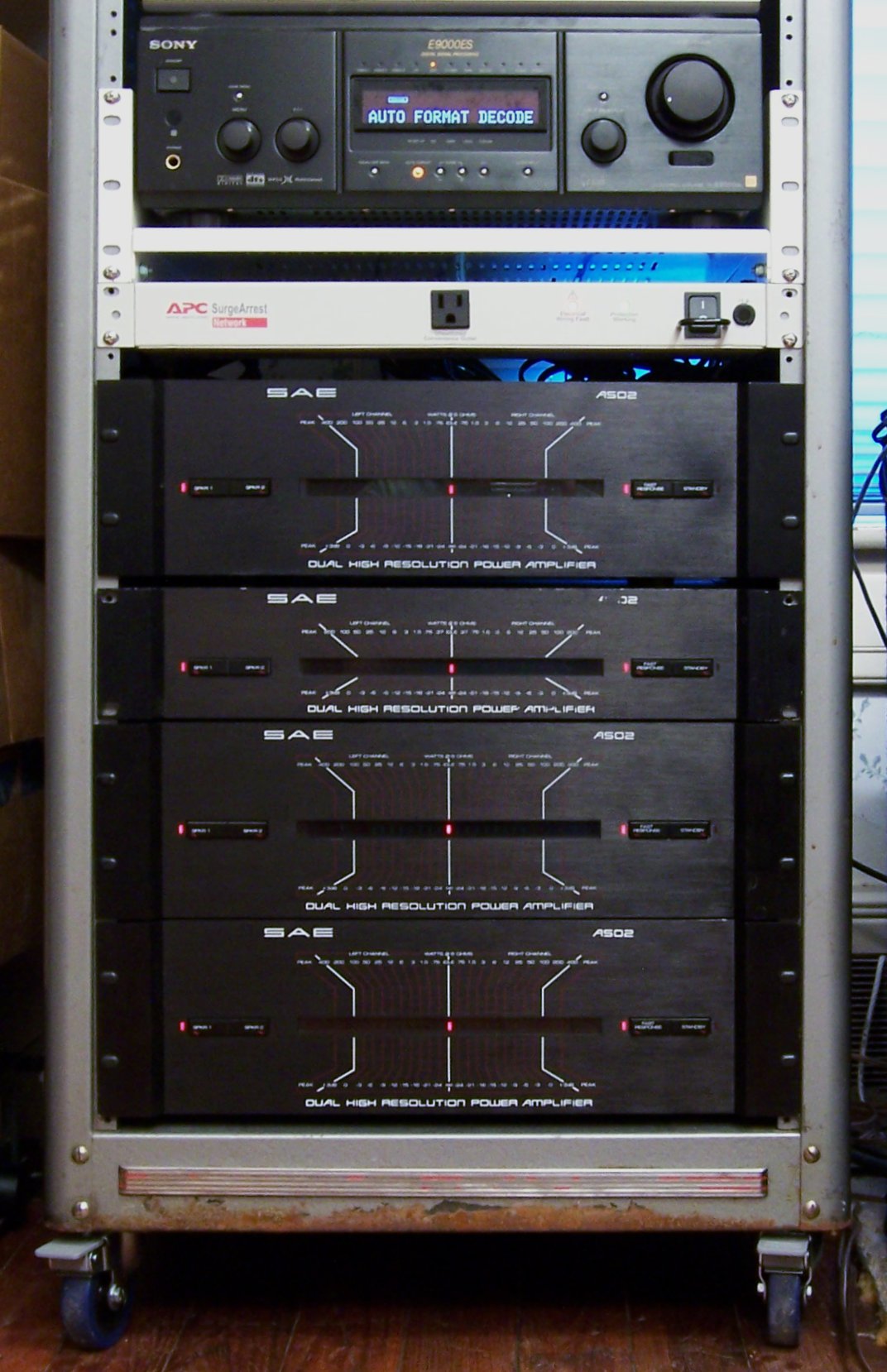
The project I’ve been working on lately is a power sequencer for my SAE A502 and A202 amplifiers. I bought my first A502 with summer job money when I was in college, and recently I’ve bought a few more on eBay. They’re big and beefy and I love ‘em.

My stereo rack, with Sony preamp and SAE amplifier stack

Their only drawback is that they have to be switched on and off manually — they’re not tied to my preamp. This is particularly annoying to my wife who hates all things electronic — she just wants to watch TV or a movie, and she has to fiddle with all these buttons to get the sound to come on.

Well, not any more.

Standby Circuit

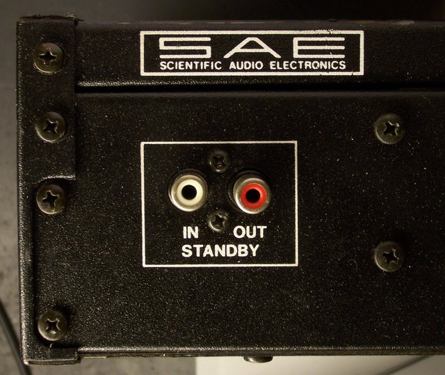
Many of the SAE amplifiers, particularly including the “02″ series, have standby inputs. The SAE preamplifier puts out a signal telling the amplifiers when to turn on and off, and the whole stack is controlled by the preamp.

SAE amplifier standby input

Which is great if you have an SAE preamp and you just want to listen to stereo audio — but SAE went out of business long before the advent of home theater surround sound, much less 5.1 surround. If you want surround, you’re not using an SAE preamp; and if you’re not using an SAE preamp, you’re turning your amplifiers on and off by hand.

I’ve long dreamed of building a box to do that for me, and now I’ve done it.

The first step was determining how the standby signalling is done. The owner’s manual isn’t much help; it doesn’t list the details of the protocol, but only describes (in rather roundabout language) that you need to manually turn the amp on and let the preamp turn it off.

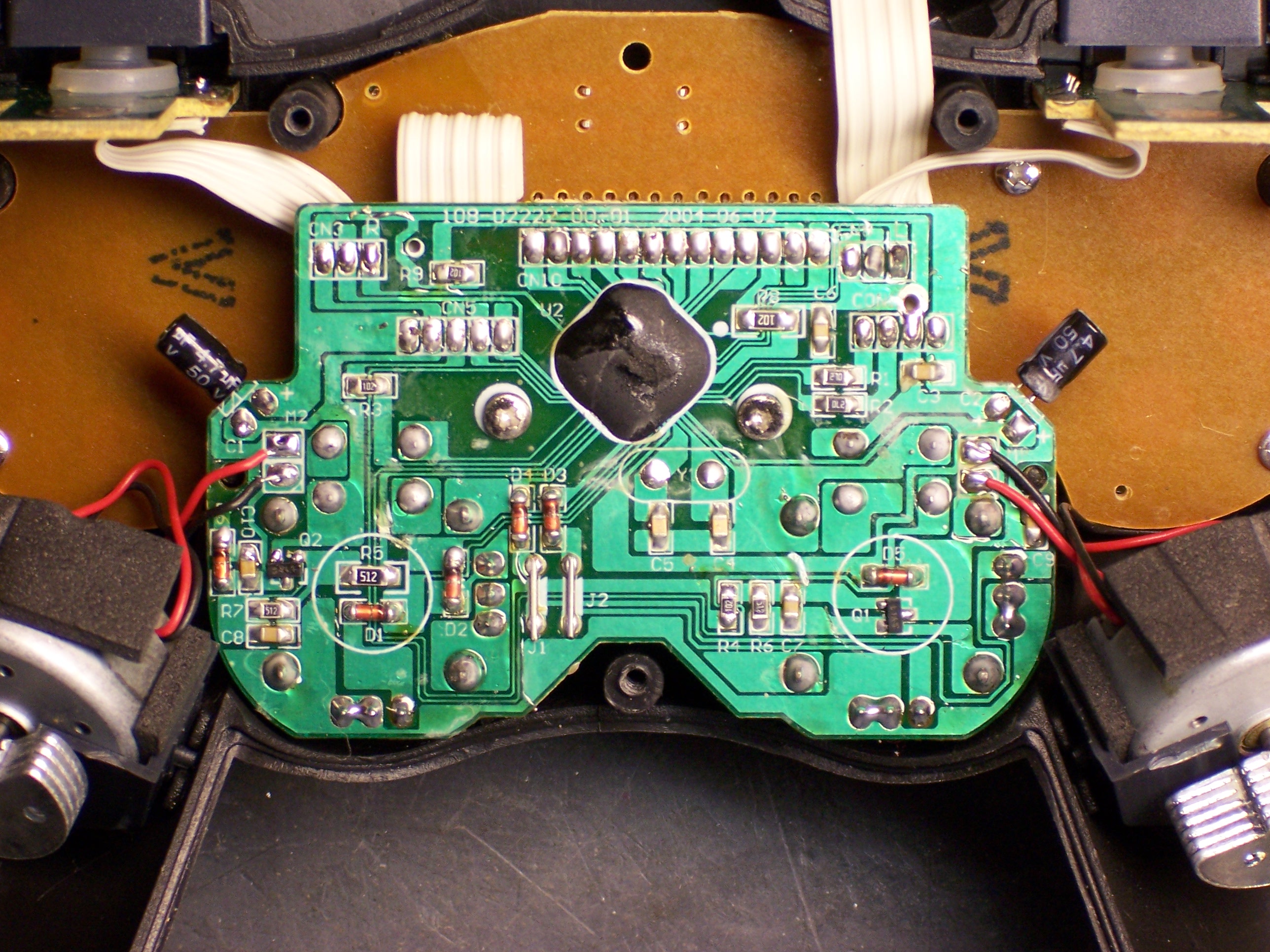
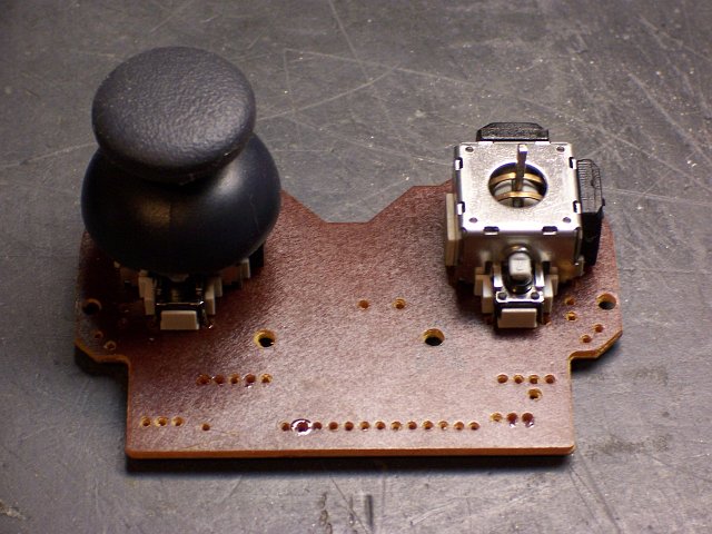
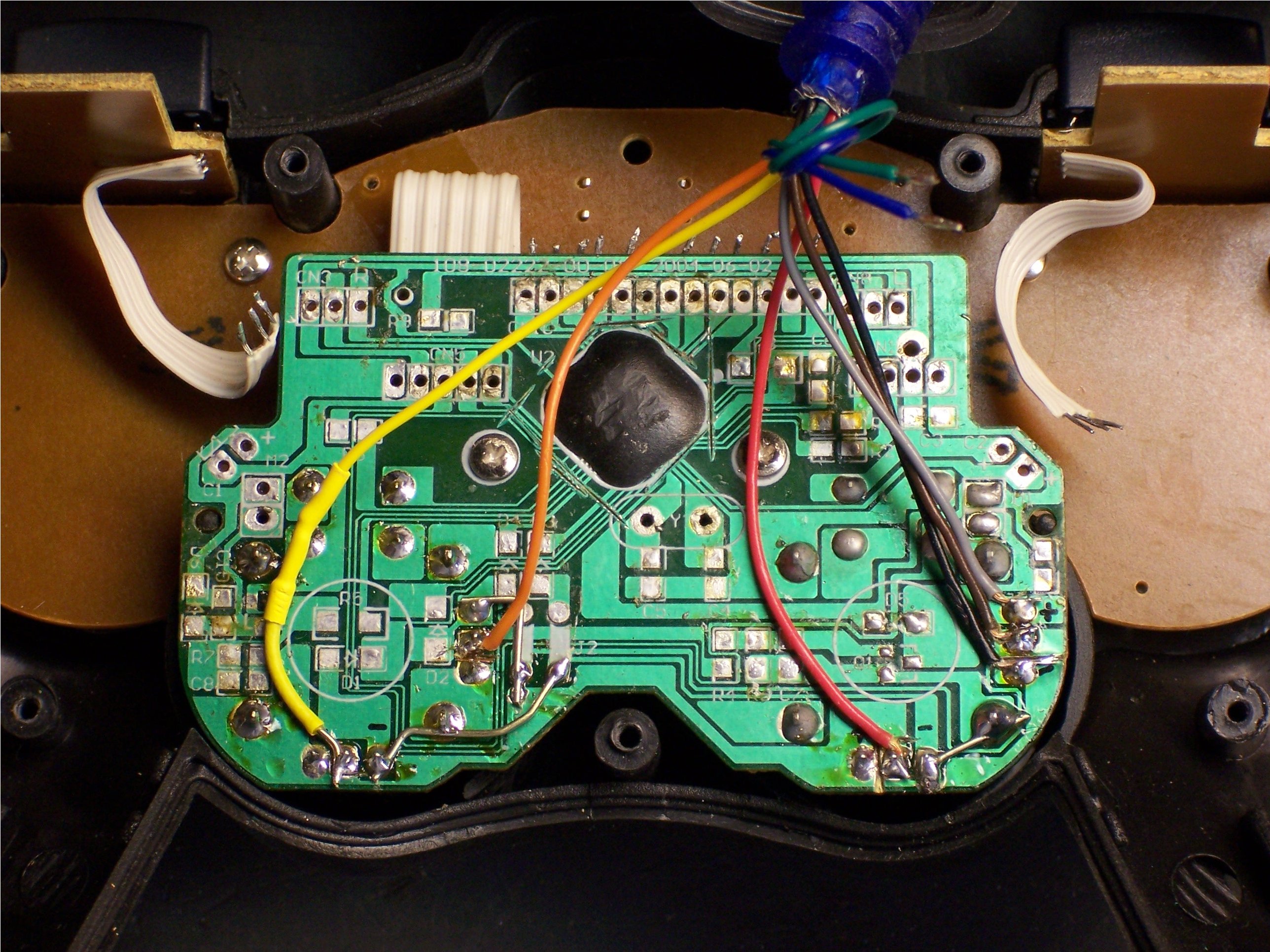
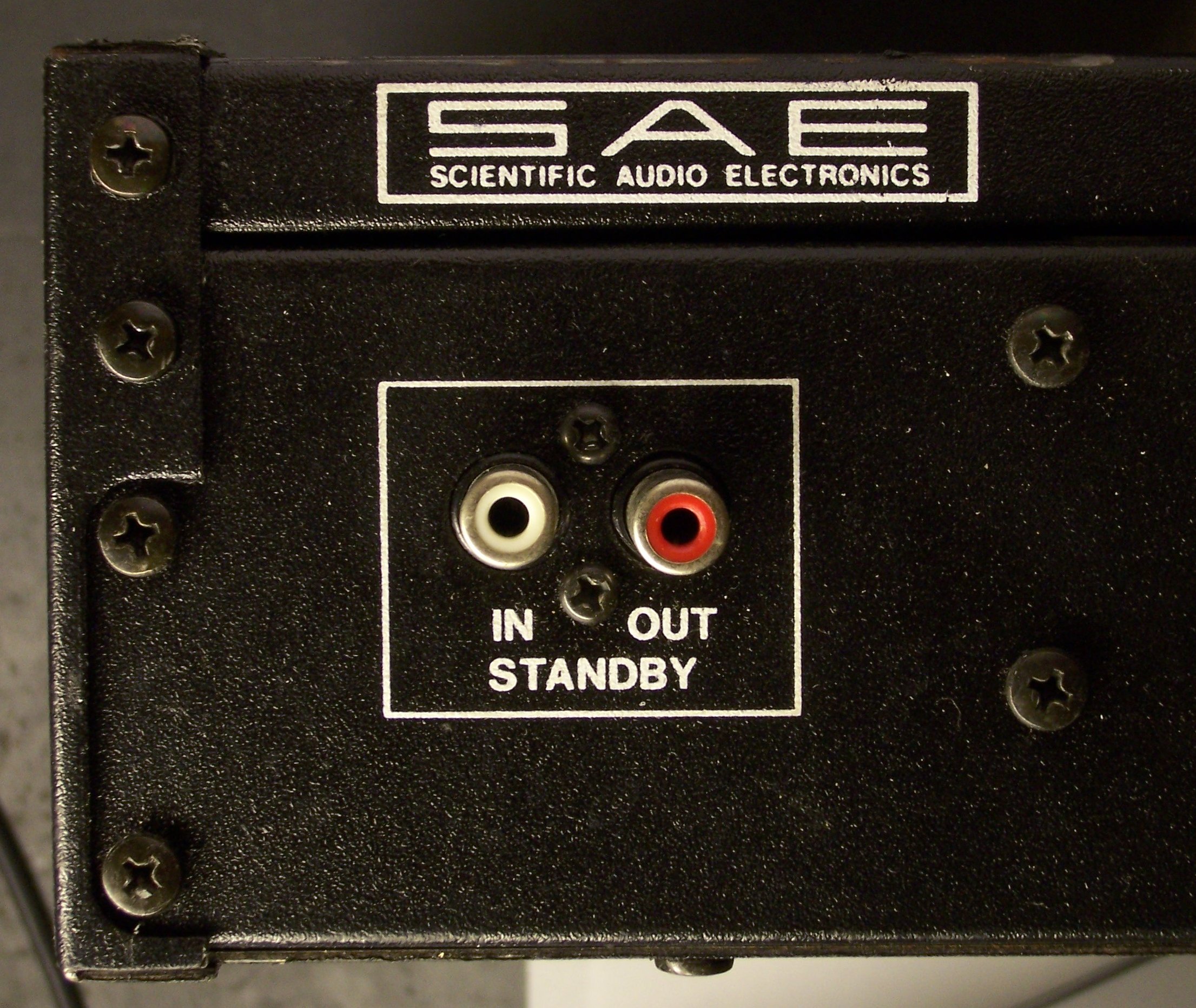
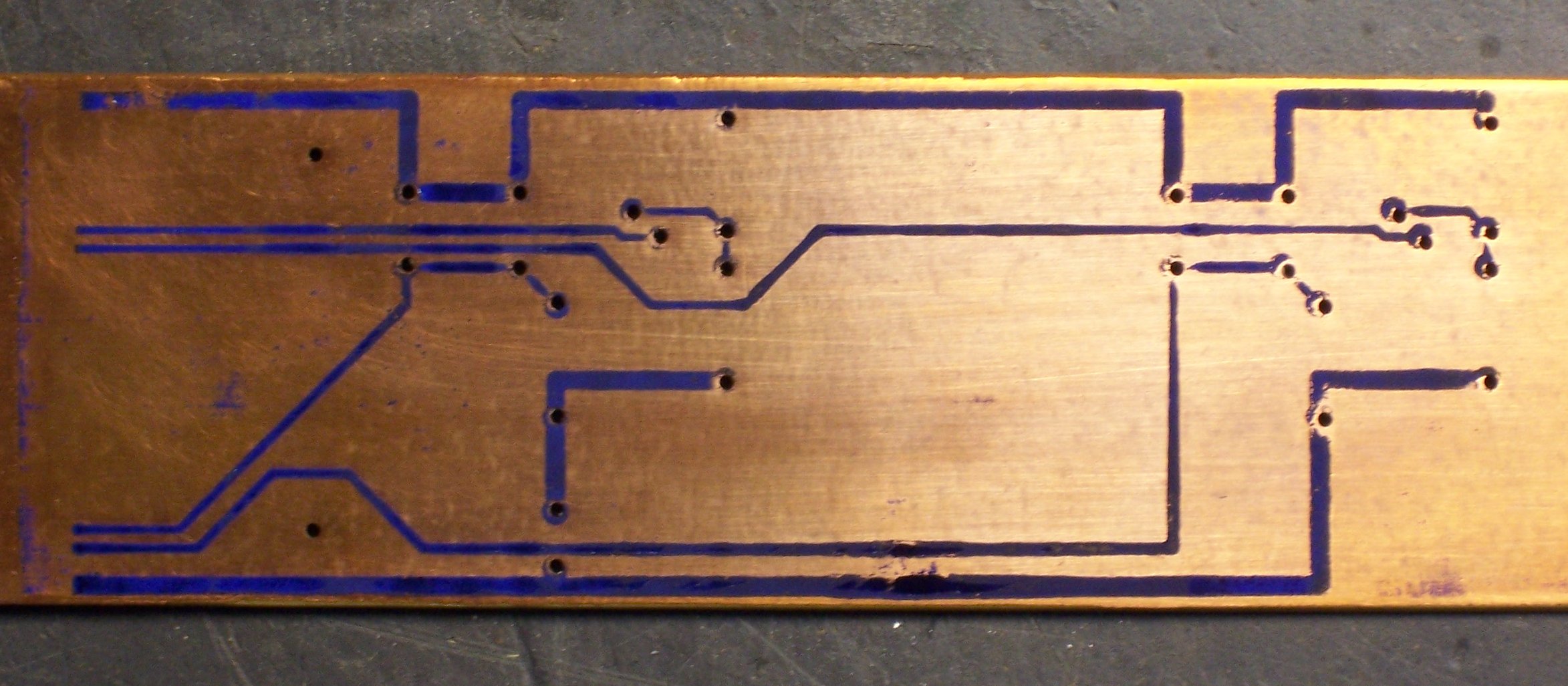
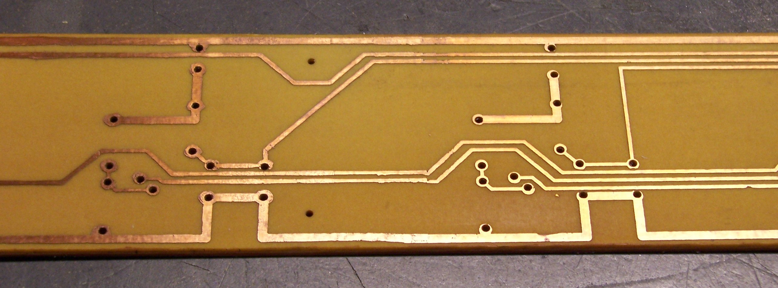
So I opened an amplifier and looked at its standby board. The circuitry is very simple, and I’ve since confirmed my schematic against the amplifier’s official schematic.

SAE amplifier standby circuit

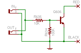
The “input” and “output” jacks are identical and tied directly together, with the tips feeding the base of an NPN transistor. Put a small amount of current through the tip and the transistor will shunt the red wire’s voltage to ground.

Inside the amp, the red wire connects to the base of a Darlington pair that drives the main power relay. Steal its base current and the relay can’t switch the main power on; hence the standby is an override to keep the amp off, as the manual described.

Knowing that, it’s very simple to build a device to control the amplifiers.

Watching the Preamp

The question that remains is how to know when it’s time to turn on. In my case, since I have an A/V preamp, I thought the preamp put out a video signal any time it was on (even if it was just a bluescreen when no inputs are active). It turns out I was wrong, but this was still a productive train of thought.

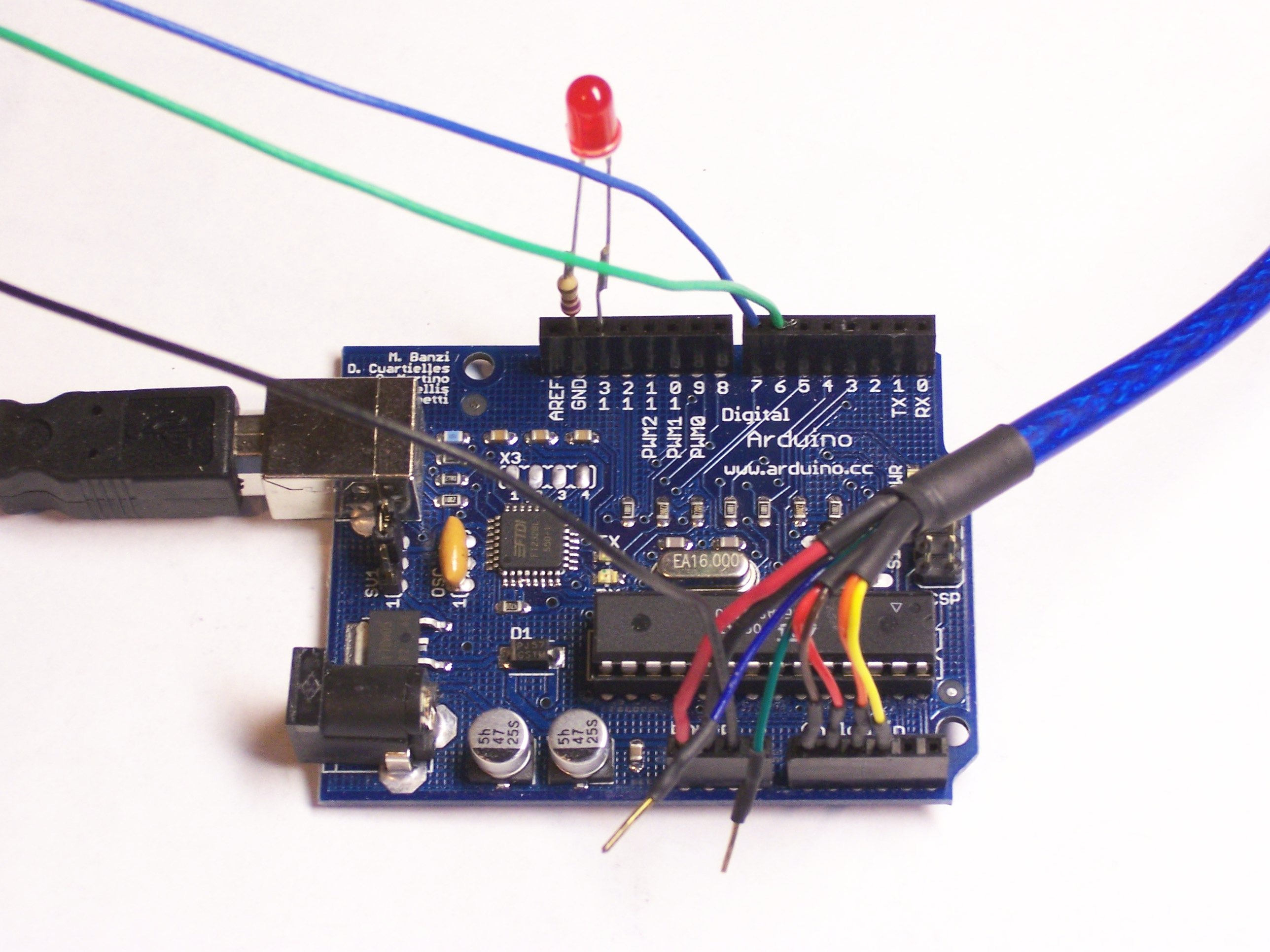
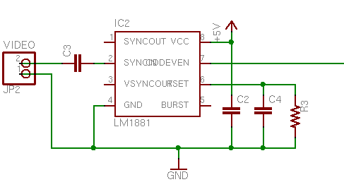
I used an LM1881 video sync separator chip to watch a video connection. The chip ends up generating sync signals if none are present, so I couldn’t use its sync outputs to detect the presence of video; but it has a logic-level odd/even frame output that oscillates at 30Hz whenever an interlaced video signal is being received. Repeated rising (or falling) edges == video present.

LM1881 video detection circuit

I had already built and tested the circuit before I discovered that my preamp most certainly does not output video when it’s on, unless it actually has a video input on as well. That was very disappointing, since I don’t want the system dependent on a third device that supplies video — it should work whether I’m watching a movie, listening to a CD, or listening to 8-track.

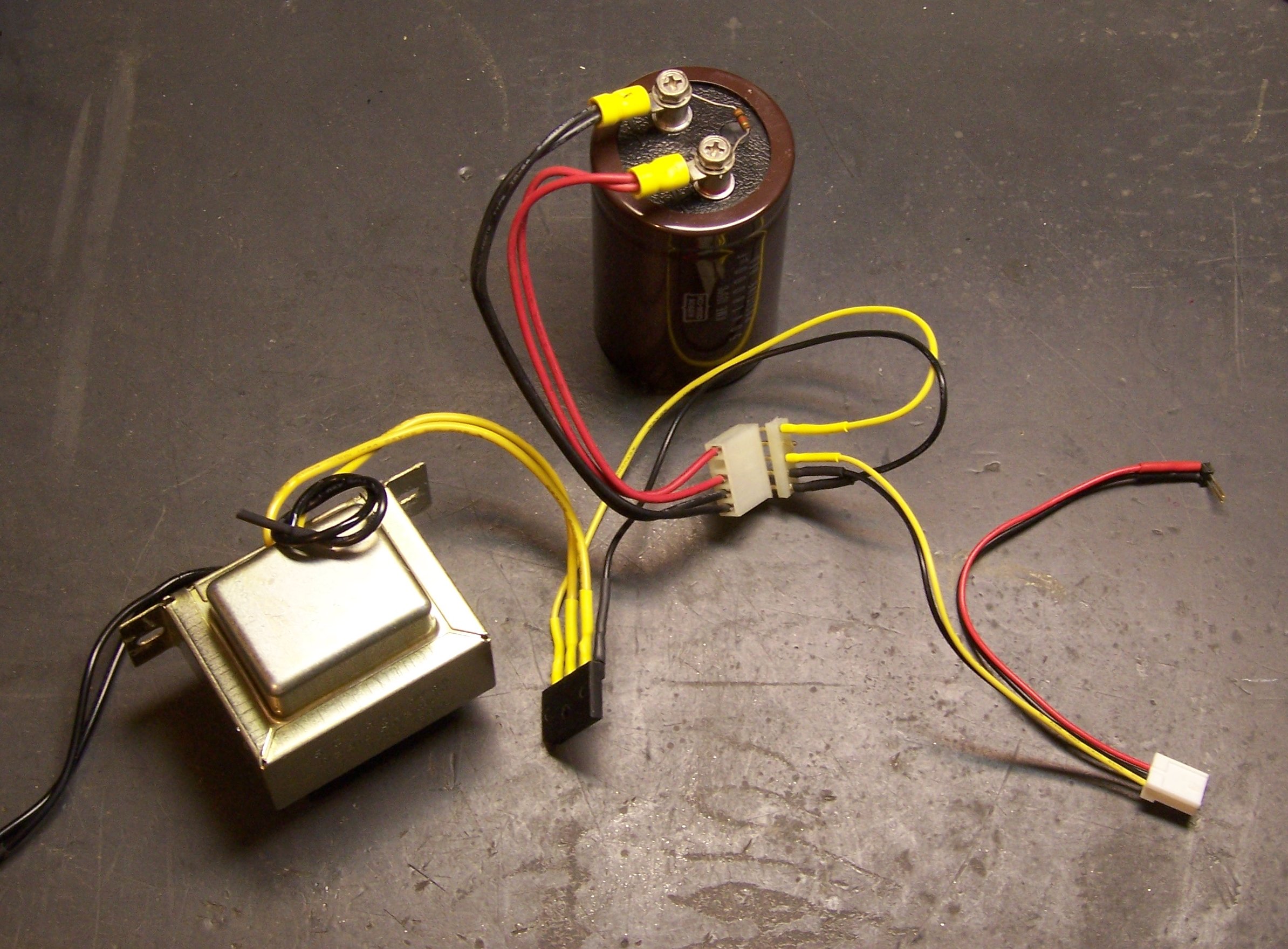
Skulking around for alternatives, the best I could come up with was the switched outlet on the back of my preamp. I bought a slim 5V wall wart to plug into the back of the preamp and added another detection circuit to rectify and regulate an arbitrary low-voltage input.

Switched power detection circuit

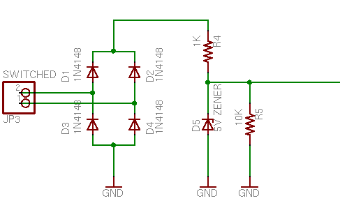
The preamp powers up, the switched recep comes on, 5V feeds into the bridge rectifier, and a logic high feeds out. The input would do just as well detecting a low-voltage AC wall wart . . . if I had remembered to put a capacitor between the diode bridge and R4. Duly noted for the next version.

Control Logic

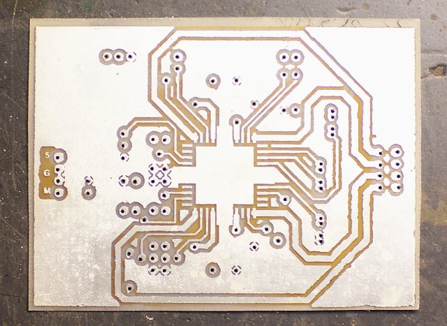
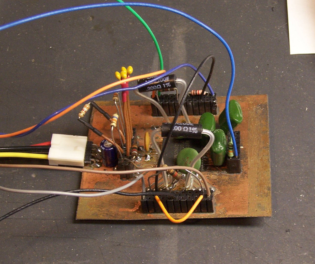
Cort was saying that I should have built the whole circuit out of discrete TTL logic, and I could indeed have done so, for a little retro charm. However, I wanted additional control that would have raised my chip count too high, so I built the control with a PIC.

When the preamp comes on, the sequencer turns on all four amps, one at a time, to spread out the inrush current. (Could have used a clock and a shift register.) But all four amps are only needed when watching movies — listening to music requires only the front and sub channels, not the center and rear. I wanted manual override pushbuttons so I could turn off the unused amps. (Could have used S-R latches.)

Additionally, when Cort and I were discussing what should happen to manual selections when the preamp eventually turns off, he suggested having a fully manual mode that ignores the signal detector inputs and heeds only the front-panel pushbuttons. (Could have . . . naahhhhh.)

Ultimately, I ended up using every available I/O pin on my PIC18F232:

  • 1 capture/compare input pin to watch the video signal
  • 1 input pin to watch the switched power signal
  • 2 output pins to run the bicolor power/mode LED
  • 4 input pins to watch the front-panel pushbuttons
  • 4 I/O pins to run bicolor amplifier status LEDs using the tristate trick
  • 4 output pins to control the amplifier standby inputs

I wrote the code in LogoChip Logo, with subroutines to service the input modules and a state machine to control the different modes. All of the timing is done in software, including the delay between turning on consecutive amps, and a loss-of-video countdown timer to keep short glitches from bouncing the amps.
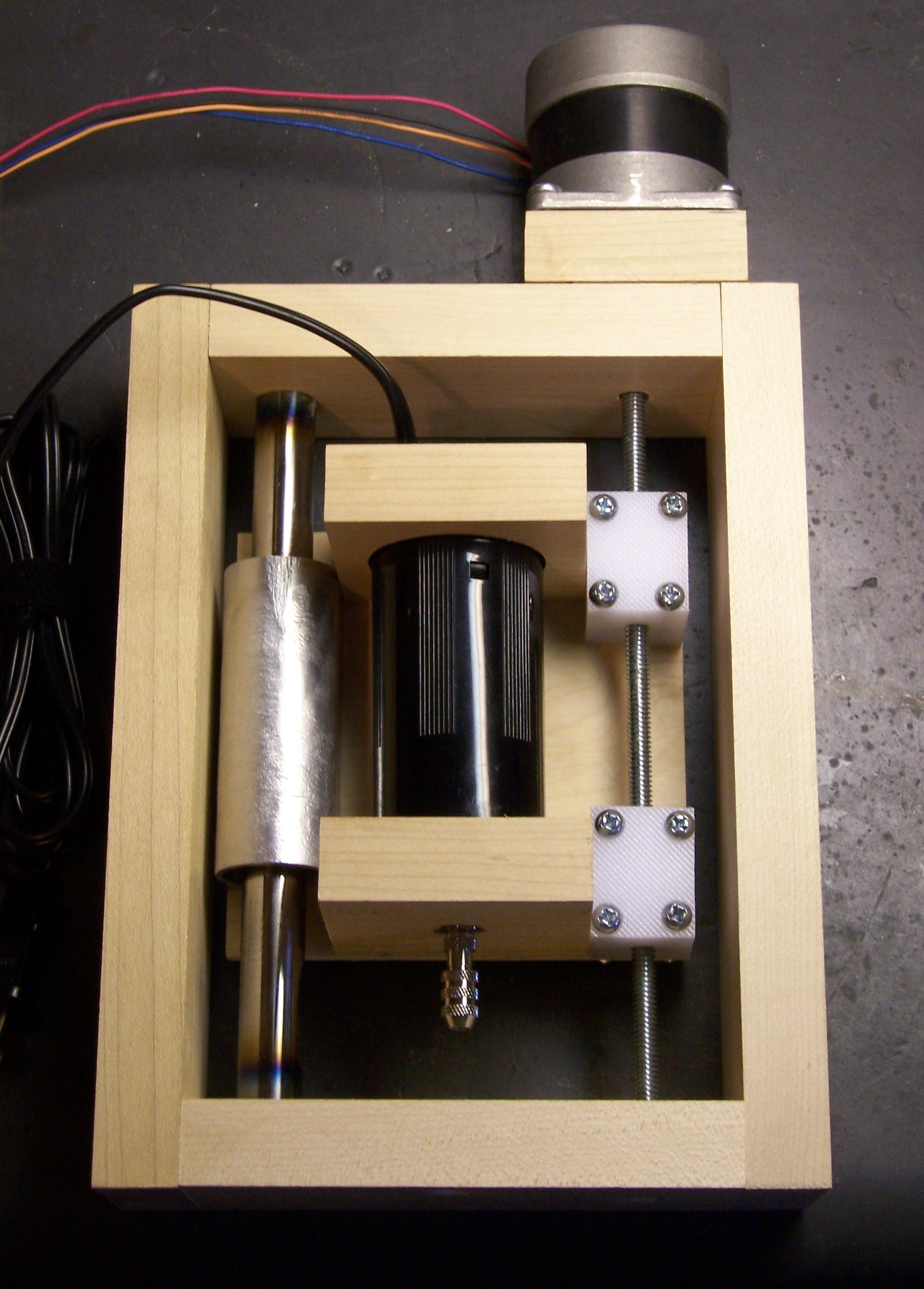
Sequencer in Action

The video detector wasn’t a waste; I plugged a spare output of my DVD player into it, so the amps come on when the DVD player is turned on or the preamp is turned on, whichever comes first.

Here’s a video of me turning on the DVD player and the sequencer (just above the amp stack) turning on the amps, then turning off the DVD player and the sequencer turns off the amps after a delay. If you have audio turned on, you can hear the amps’ relays clicking in sync with the sequencer LEDs, then later clicks as the delayed speaker relays engage.

This is really slow to load; I’m working on migrating this to YouTube.

These are too slow to load and are causing problems with my browser. You’re welcome to paste in the URL and try them if you like.

embed src=”http://www2.neufeld.newton.ks.us/images/electronics/2007/08/06/100_3046.mov” controller=”true” width=”480″ height=”656″ kioskmode=”false” autoplay=”false” pluginspage=”http://www.apple.com/quicktime/download/”>

There’s one little snag — the standby circuit on my top amplifier isn’t working, so I’m still turning it on and off manually. I just bought an SAE preamp on eBay and should receive it within a week or so, at which point I’ll hook it up and see whether it has magic juju that my sequencer doesn’t, or whether I need to troubleshoot my amp.

Here’s a nearly identical video of me turning on the preamp and the sequencer turning on the amps.

embed src=”http://www2.neufeld.newton.ks.us/images/electronics/2007/08/06/100_3047.mov” controller=”true” width=”480″ height=”656″ kioskmode=”false” autoplay=”false” pluginspage=”http://www.apple.com/quicktime/download/”>

Kits for Sale

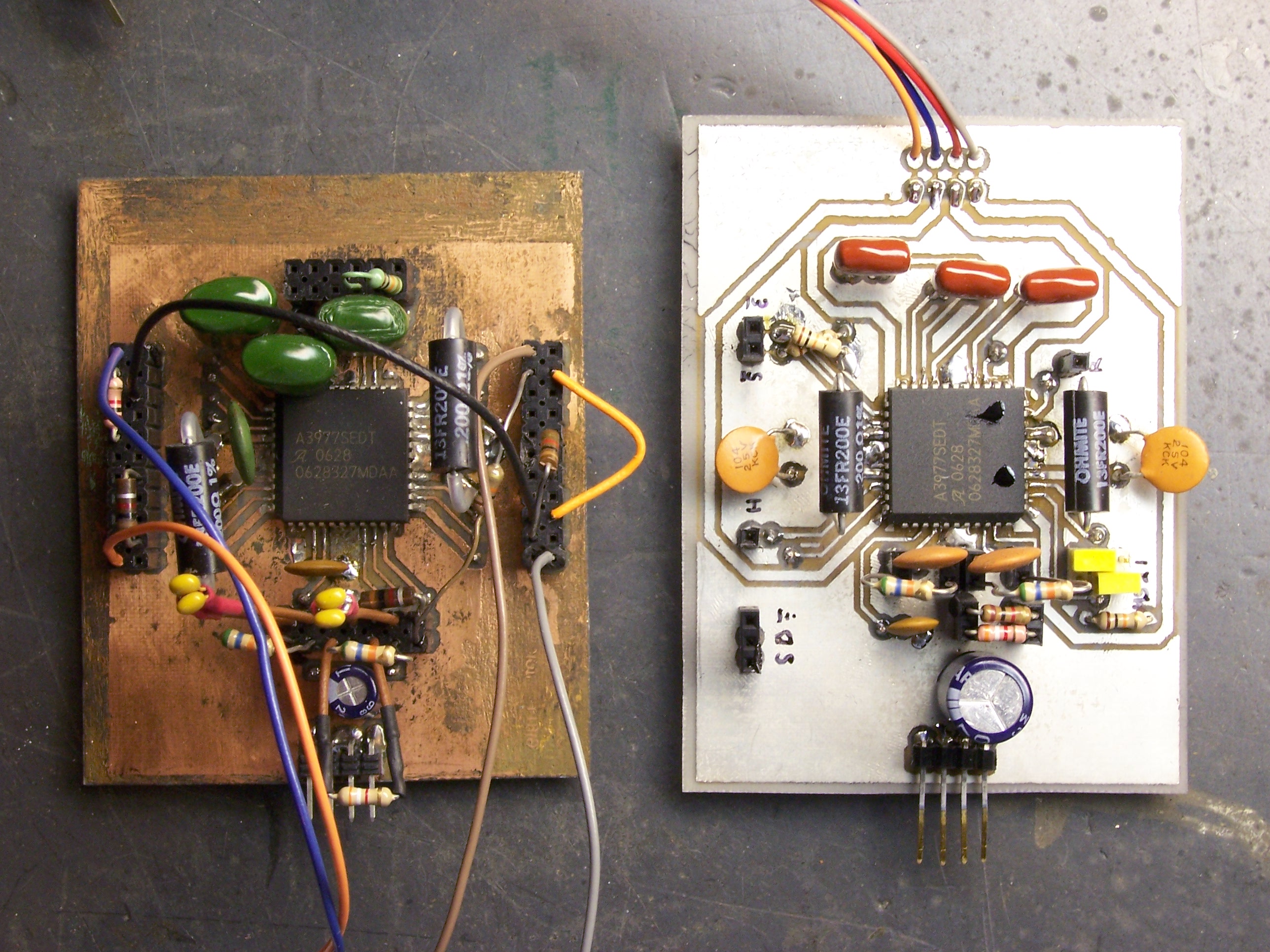
Well, not yet, but I’m interested in pursuing it. There’s a pretty active community of SAE equipment owners, and I have to believe there’d be other folks in the same position, using SAE amps with non-SAE preamps. After I work through a few issues, I’d like to offer the power sequencer in both kit and appliance form and see if I can sell a few.

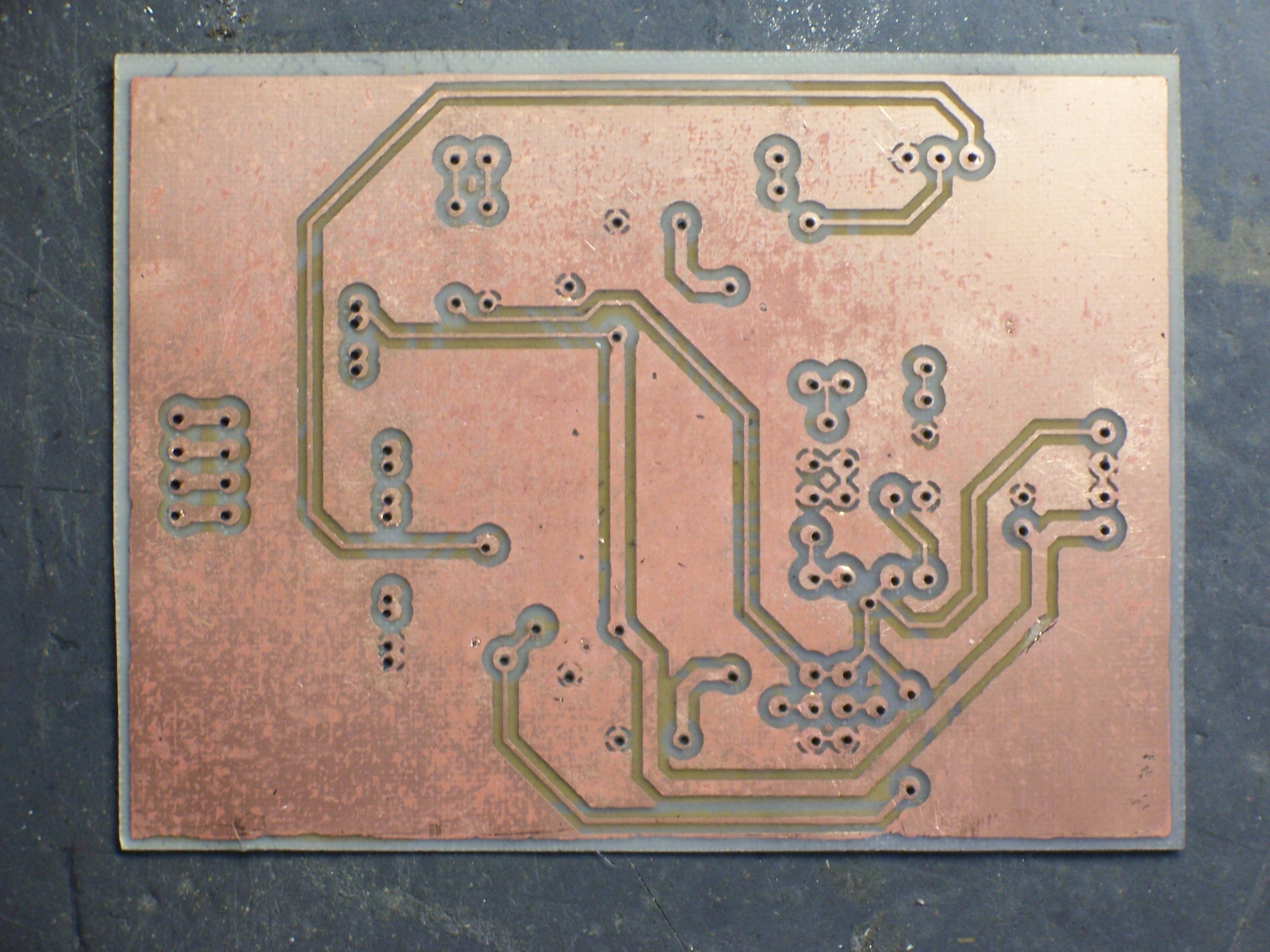
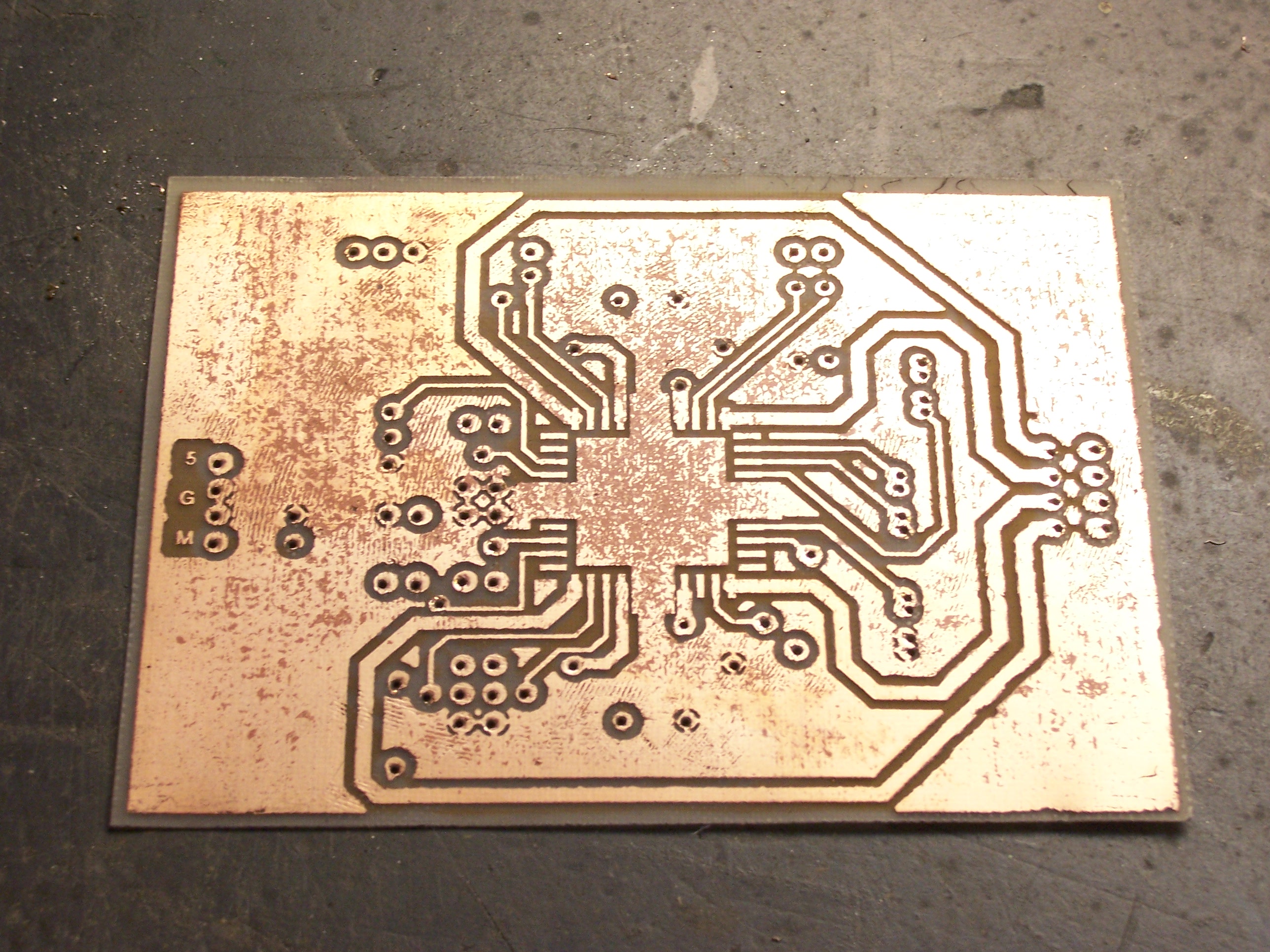
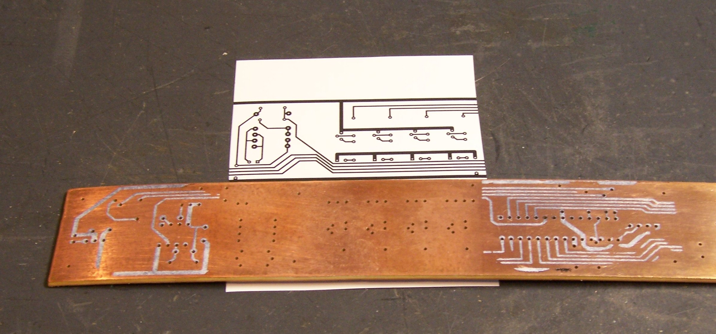
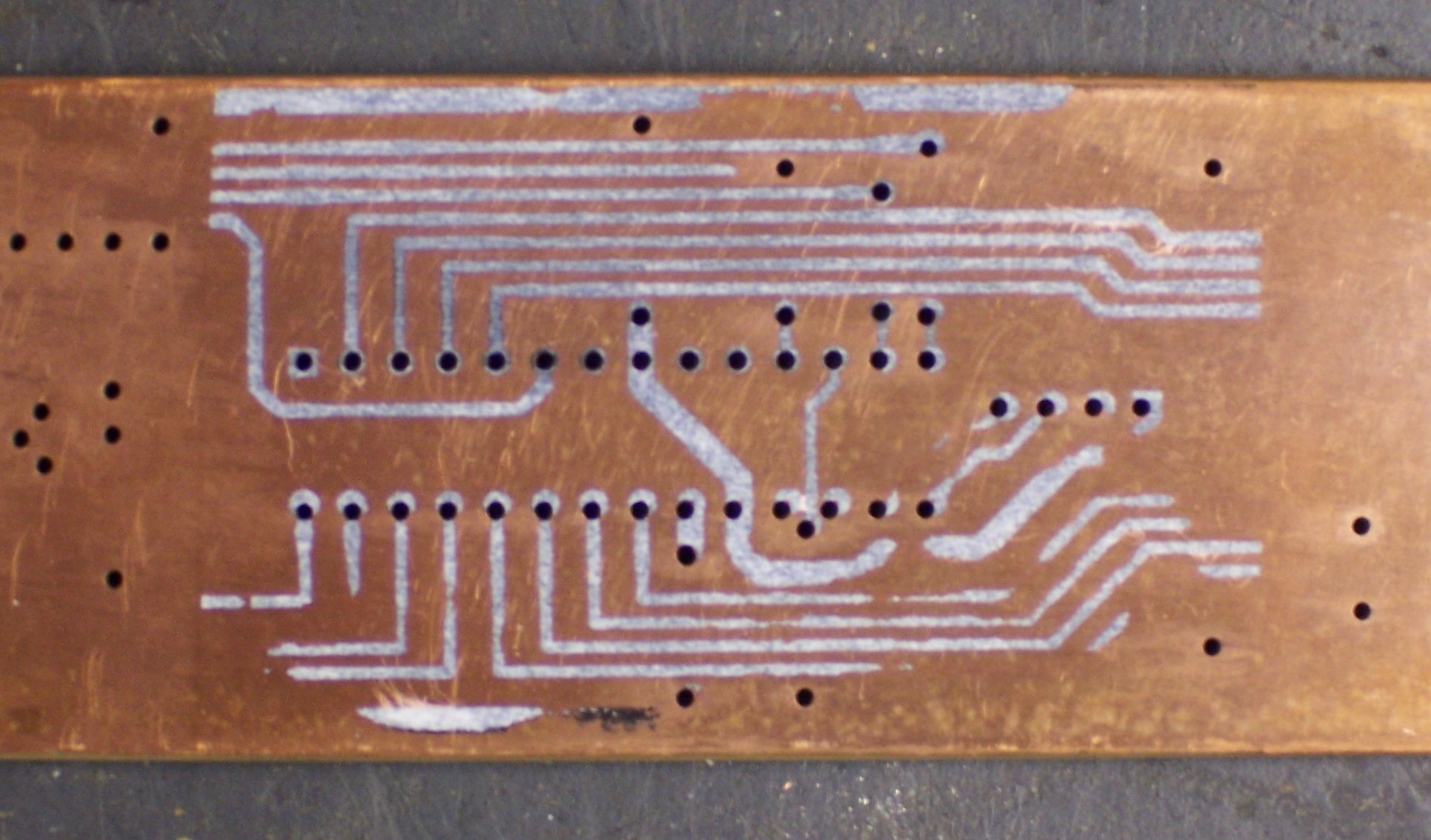
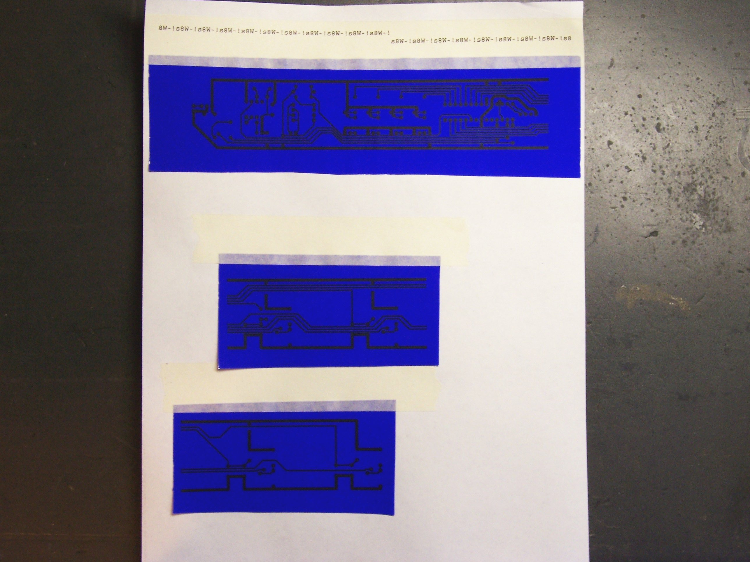
I want to split the main circuit board into a front-panel board and a control board, to make it easier for other folks to adapt the LED and button spacing to fit enclosures of their own choice. That also solves the problem with the RJ-45 jack, as it could then be on the component side of the control daughterboard. And I made some mistakes in the physical size and mounting of the board that I’d like to correct as well.

Once I touch up the circuit and board designs and clean up my code, I want to release the whole schmear under a Creative Commons license, probably Attribution Share Alike. Lady Ada’s Creative-Commons-licensed kits are pretty inspiring to me, and I’d like to think there’s a small but healthy market for kits and appliances that don’t rely on keeping the design closed and secret.

Wish me luck!

PCB Iron-On Etch Resist Problems (and Solutions)

Monday, August 6th, 2007

After drilling my board (and finally getting the right holes in the right order), I took it back home to etch. I wanted to print an etch-resist mask on my laser printer and iron it onto the board, and I wanted to do it using plain, glossy paper.

Pads and Holes

I had originally laid out the board using default sizes of 28 mil holes and 50 mil pads. Since I broke too many drill bits and ended up drilling with a 39 mil bit, that would have left me only 5.5 mils of copper surrounding each hole. That’s not nearly enough to solder to, much less enough to consistently align with an iron-on transfer. I went back into FreePCB and increased all the pad sizes to 70 mil, to give about 15 mil of copper around each hole.

Lesson: Keep a good supply of small drill bits.

Lesson: Don’t bump up to larger drill bits if you run out of small ones. Wait for more of the right size.

Lesson: Use larger pads than default when laying out a board for iron-on transfer.

Ironing in Pieces

Once I had increased the pad size, I exported the bottom copper layer as an image file. (FreePCB doesn’t seem to have a working Print function.) Because the bottom layer is drawn from the perspective of the top of the board, one would normally mirror it to view how it would look from the bottom. But the iron-on process reverses the image, so I needed to print it unmirrored.

Lesson: Export/print the bottom copper layer unmirrored when making iron-on transfers.

Because the 16.8″ length of my PCB was greater than the size of paper my printer accepts, and because the printer doesn’t seem to print at exactly accurate size, I used the GIMP to chop the image into three pieces, to iron on in sections. I split the image in areas with no holes and all horizontal traces so it’d be easy to line up, and I left about 1/4″ of overlap at each joint so I’d double up toner on the board rather than taking any chance of having a gap.

Ironing laser toner onto a PCB for etch resist, in sections

I ironed the two outer sections onto the board using our household iron set at 350°F and no steam, then soaked the board for half an hour to soften the paper and carefully peeled it off.

Iron-on PCB toner transfer with poor adhesion

A lot of the traces came off with the paper. It didn’t feel like I had peeled the traces off the PCB — it felt like they had never adhered in the first place. Reinforcing that suspicion was how much effort it took to clean the traces off the board and start over — the ones still on the board were well stuck. I ended up using acetone to clean them off the board.

I printed another copy and ironed it on, using the maximum temperature on the iron and the Giles Corey method (more weight). This time I soaked the board for over an hour. Once again, large sections of traces peeled away.

Press ‘n’ Peel Blue and Successful Ironing

I have a few sheets of Press ‘n’ Peel Blue that Joel bought and encouraged me to test drive, and I’d had reasonably good luck the previous time I tried them, so I got them out. To avoid wasting an entire sheet of Blue, I printed the design onto a carrier sheet of plain paper, then cut appropriate-sized sections of Blue and masking-taped them to the paper over the printed areas and printed again.

Press 'n' Peel Blue

You can see across the top where my printer went nuts printing PostScript source code on the first try, but I got the design printed onto the Blue on the second try. I ironed a section of Blue onto the freshly-scrubbed PCB board, and . . .

Press 'n' Peel Blue iron-on PCB transfer; no adhesion around holes

Excellent adhesion most places; terrible adhesion around the holes.

So what’s different about the holes? I think they’re dimpled from when the drill hits the copper and before it starts to bite. The surface is slightly lower, and there’s not enough pressure to adhere the Blue (or the plain-paper transfer) to the copper.

I needed something between the iron and the transfer to help distribute the pressure, even down into slight surface variations. I considered a sheet of felt, but I was afraid that it would be too soft to distribute the pressure well. I settled on a kitchen paper towel folded in half, and voila!

Press 'n' Peel Blue iron-on PCB transfer; good adhesion throughout

Good adhesion everywhere!

Lesson: Use a thin pad between the iron and the toner transfer to help distribute pressure through surface irregularities.

Etching

I had struggled for a couple of weeks to think of an appropriate etching tank for a board of this size. I needed a plastic or glass tank long enough for the board — but preferably also narrow, so as not to require a huge amount of etchant to cover the board. Finally I thought of a section of PVC pipe, capped and slit in half. $20 and a trip to the bandsaw later, I had an etching tank. (Two, actually.)

Lesson: It’s surprisingly difficult to fully seat a cap on 3″ PVC before the cement sets.

PVC etching tank

I set the tank over the bathroom sink with the ends on paper towels, in case my PVC glue joints weren’t watertight. Good thing, too, since they weren’t. By the end of the etch, one of the paper towels was stained, and I was particularly glad I’d used it.

Lesson: Use lots and lots of PVC cement to get watertight joints for odd configurations and applications.

At first, the etchant appeared to be removing quite a bit of copper, as evidenced by its increasing opacity. Half an hour in, though, not much was happening, even though I dropped by every few minutes to agitate the tank.

After a while, I got the bright idea to heat the etchant with my heat gun, and the etching really took off at that point, proceeding at a nearly visible pace.

Lesson: Heat the etchant to at least 100°F.

Once all the unwanted copper was etched away, I used a plastic fork to remove the board from the tank and rinsed it under lots of running water. Then I went to the kitchen sink to filter the used etchant into an empty plastic bottle for later reuse.

Lesson: Coffee filters pass about 1/4 cup of liquid etchant before becoming strangely impermeable.

Lesson: Impermeable coffee filters do not make particularly good funnels.

Lesson: Poor funnels tend to spill liquid over the edge into the white porcelain sink.

Lesson: Poor funnels tend to slip down inside the plastic bottle.

Lesson: The nooks at each end of capped PVC hold quite a bit of etchant that spills all over when you’re trying to pour it out.

Lesson: Start the etchant recovery process a couple of hours before your wife comes home so you have plenty of time to scrub the sink.

Results

Etched, cleaned PCB

After cleaning the toner off the board with acetone, the traces really look nice. They have reasonably crisp edges and not too bad dropouts. This ended up being one of the nicer boards I’ve made by home etching.

Lesson: Try plain-paper toner transfer next time, using the paper towel pad trick.