The project I’ve been working on lately is a power sequencer for my SAE A502 and A202 amplifiers. I bought my first A502 with summer job money when I was in college, and recently I’ve bought a few more on eBay. They’re big and beefy and I love ‘em.
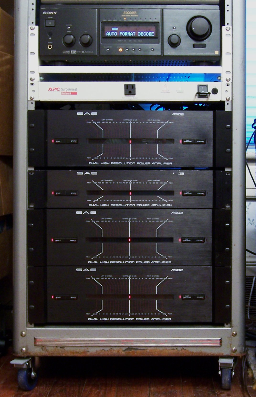
Their only drawback is that they have to be switched on and off manually — they’re not tied to my preamp. This is particularly annoying to my wife who hates all things electronic — she just wants to watch TV or a movie, and she has to fiddle with all these buttons to get the sound to come on.
Well, not any more.
Standby Circuit
Many of the SAE amplifiers, particularly including the “02″ series, have standby inputs. The SAE preamplifier puts out a signal telling the amplifiers when to turn on and off, and the whole stack is controlled by the preamp.
Which is great if you have an SAE preamp and you just want to listen to stereo audio — but SAE went out of business long before the advent of home theater surround sound, much less 5.1 surround. If you want surround, you’re not using an SAE preamp; and if you’re not using an SAE preamp, you’re turning your amplifiers on and off by hand.
I’ve long dreamed of building a box to do that for me, and now I’ve done it.
The first step was determining how the standby signalling is done. The owner’s manual isn’t much help; it doesn’t list the details of the protocol, but only describes (in rather roundabout language) that you need to manually turn the amp on and let the preamp turn it off.
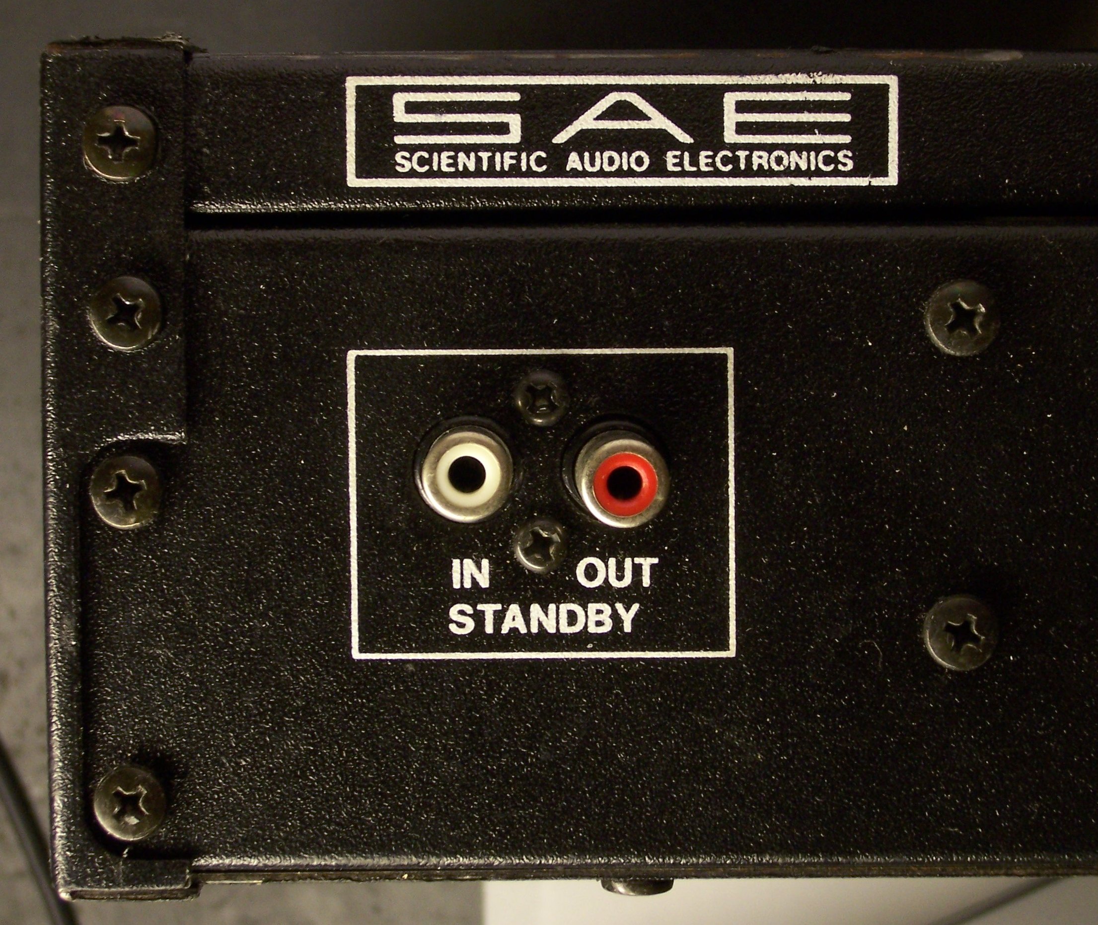
So I opened an amplifier and looked at its standby board. The circuitry is very simple, and I’ve since confirmed my schematic against the amplifier’s official schematic.
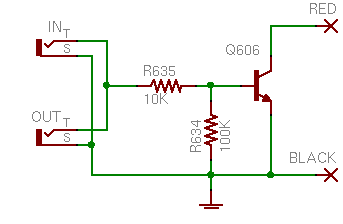
The “input” and “output” jacks are identical and tied directly together, with the tips feeding the base of an NPN transistor. Put a small amount of current through the tip and the transistor will shunt the red wire’s voltage to ground.
Inside the amp, the red wire connects to the base of a Darlington pair that drives the main power relay. Steal its base current and the relay can’t switch the main power on; hence the standby is an override to keep the amp off, as the manual described.
Knowing that, it’s very simple to build a device to control the amplifiers.
Watching the Preamp
The question that remains is how to know when it’s time to turn on. In my case, since I have an A/V preamp, I thought the preamp put out a video signal any time it was on (even if it was just a bluescreen when no inputs are active). It turns out I was wrong, but this was still a productive train of thought.
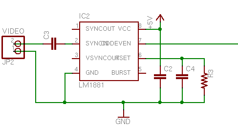
I used an LM1881 video sync separator chip to watch a video connection. The chip ends up generating sync signals if none are present, so I couldn’t use its sync outputs to detect the presence of video; but it has a logic-level odd/even frame output that oscillates at 30Hz whenever an interlaced video signal is being received. Repeated rising (or falling) edges == video present.
I had already built and tested the circuit before I discovered that my preamp most certainly does not output video when it’s on, unless it actually has a video input on as well. That was very disappointing, since I don’t want the system dependent on a third device that supplies video — it should work whether I’m watching a movie, listening to a CD, or listening to 8-track.
Skulking around for alternatives, the best I could come up with was the switched outlet on the back of my preamp. I bought a slim 5V wall wart to plug into the back of the preamp and added another detection circuit to rectify and regulate an arbitrary low-voltage input.
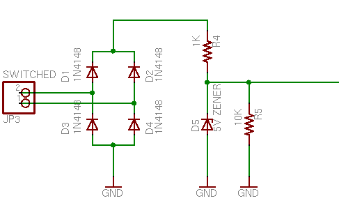
The preamp powers up, the switched recep comes on, 5V feeds into the bridge rectifier, and a logic high feeds out. The input would do just as well detecting a low-voltage AC wall wart . . . if I had remembered to put a capacitor between the diode bridge and R4. Duly noted for the next version.
Control Logic
Cort was saying that I should have built the whole circuit out of discrete TTL logic, and I could indeed have done so, for a little retro charm. However, I wanted additional control that would have raised my chip count too high, so I built the control with a PIC.
When the preamp comes on, the sequencer turns on all four amps, one at a time, to spread out the inrush current. (Could have used a clock and a shift register.) But all four amps are only needed when watching movies — listening to music requires only the front and sub channels, not the center and rear. I wanted manual override pushbuttons so I could turn off the unused amps. (Could have used S-R latches.)
Additionally, when Cort and I were discussing what should happen to manual selections when the preamp eventually turns off, he suggested having a fully manual mode that ignores the signal detector inputs and heeds only the front-panel pushbuttons. (Could have . . . naahhhhh.)
Ultimately, I ended up using every available I/O pin on my PIC18F232:
- 1 capture/compare input pin to watch the video signal
- 1 input pin to watch the switched power signal
- 2 output pins to run the bicolor power/mode LED
- 4 input pins to watch the front-panel pushbuttons
- 4 I/O pins to run bicolor amplifier status LEDs using the tristate trick
- 4 output pins to control the amplifier standby inputs
I wrote the code in LogoChip Logo, with subroutines to service the input modules and a state machine to control the different modes. All of the timing is done in software, including the delay between turning on consecutive amps, and a loss-of-video countdown timer to keep short glitches from bouncing the amps.
Sequencer in Action
The video detector wasn’t a waste; I plugged a spare output of my DVD player into it, so the amps come on when the DVD player is turned on or the preamp is turned on, whichever comes first.
Here’s a video of me turning on the DVD player and the sequencer (just above the amp stack) turning on the amps, then turning off the DVD player and the sequencer turns off the amps after a delay. If you have audio turned on, you can hear the amps’ relays clicking in sync with the sequencer LEDs, then later clicks as the delayed speaker relays engage.
This is really slow to load; I’m working on migrating this to YouTube.
These are too slow to load and are causing problems with my browser. You’re welcome to paste in the URL and try them if you like.
embed src=”http://www2.neufeld.newton.ks.us/images/electronics/2007/08/06/100_3046.mov” controller=”true” width=”480″ height=”656″ kioskmode=”false” autoplay=”false” pluginspage=”http://www.apple.com/quicktime/download/”>
There’s one little snag — the standby circuit on my top amplifier isn’t working, so I’m still turning it on and off manually. I just bought an SAE preamp on eBay and should receive it within a week or so, at which point I’ll hook it up and see whether it has magic juju that my sequencer doesn’t, or whether I need to troubleshoot my amp.
Here’s a nearly identical video of me turning on the preamp and the sequencer turning on the amps.
embed src=”http://www2.neufeld.newton.ks.us/images/electronics/2007/08/06/100_3047.mov” controller=”true” width=”480″ height=”656″ kioskmode=”false” autoplay=”false” pluginspage=”http://www.apple.com/quicktime/download/”>
Kits for Sale
Well, not yet, but I’m interested in pursuing it. There’s a pretty active community of SAE equipment owners, and I have to believe there’d be other folks in the same position, using SAE amps with non-SAE preamps. After I work through a few issues, I’d like to offer the power sequencer in both kit and appliance form and see if I can sell a few.
I want to split the main circuit board into a front-panel board and a control board, to make it easier for other folks to adapt the LED and button spacing to fit enclosures of their own choice. That also solves the problem with the RJ-45 jack, as it could then be on the component side of the control daughterboard. And I made some mistakes in the physical size and mounting of the board that I’d like to correct as well.
Once I touch up the circuit and board designs and clean up my code, I want to release the whole schmear under a Creative Commons license, probably Attribution Share Alike. Lady Ada’s Creative-Commons-licensed kits are pretty inspiring to me, and I’d like to think there’s a small but healthy market for kits and appliances that don’t rely on keeping the design closed and secret.
Wish me luck!
DO YOU KNOW IF 2 A202 POWER AMPS CAN BE BRIDGED IN MONO?
AND IF SO HOW CAN I BRIDGE THEM?
THANK YOU,
Max, I’m going to read your question as, “Can the A202 be operated in bridged mono configuration,” to which the answer, to the best of my knowledge, is not trivially.
The A502 has provision for running in bridged mono mode. Tracing the schematic, the stereo/mono switch cuts out the right channel input, runs the left channel input through an op-amp inverter circuit to invert the phase, and feeds the inverted signal into the preamp stage.
The result is that the left channel amplifies the original mono signal and the right channel amplifies the inverted signal. Then by connecting one speaker across the left+ and right+ leads, you get twice the voltage (and concomitant power increase) as if you were connecting to left+ and GND.
The A202 has no such provision. One might be able to design an external inverter circuit to perform a similar function, but I’d advise against it unless one had an A202 schematic (I don’t) and an intimate understanding of power amplifier design.
Case in point: The A502 has numerous shutdown circuits, including DC offset. If the A202 doesn’t have a DC offset shutdown and your inverter circuit was improperly designed or tuned, you could end up amplifying an unwanted DC component, overheating the amp, and (literally) melting your speaker’s voice coil.
Sorry to bear the bad news, but I think you’re better off shopping eBay for a couple of A502s.
THANK YOU I WILL START MY SEARCH….
I have a S.A.E. A501 amp that I have had for years. It works great and I have a guy that wants to buy it. What is it worth? or is it worth keeping?
Mark, I don’t know quite how to answer. I replaced my A501 with an A502, but I never did an A-B or A-B-X comparison, so I can’t speak to the sound and I can’t offer a good recommendation.
For price, I think you’re best off watching eBay for a while or using one of the services that shows you recent auction-end prices. I know a few A501s have sold in the last few months; but not being in the market for them, I haven’t paid attention to price. I would guess they bring $75-200 plus about $40 to ship.
If you’re using the A501, and don’t have other gear that you want to replace it with, I’d say keep it. I’m personally enamored of the A502, but all the SAE stuff is really pretty good gear.
Mark, correction: I’ve never had an A501; I was thinking of a different amp.
I just saw a couple on eBay and remembered which model they are. Hang onto that baby! That’s a nice amp.
i would be interested in your kit also info or kit on using the speaker out put to run regular house light bulbs say 40 watt or less so the light would follow the increase and decrease in speaker out put .
Thanks for any information you may offer
Kevin
Have an A501 amplifier and I have blown the fuse on it. How do I go about replacing it if that’s possible? Or do I suck it up and purchase a used A501 somewhere out there?
Steve, that’s a tough question. Off the top of my head I don’t know where the fuse is on the A501 — I’d guess accessible directly from the back, but there are probably internal fuses as well.
The real issue, though, is that the fuse probably blew for a reason. If you’re lucky, the reason is that you were playing your music too loud at the same time you bumped the amplifier and the hot filament in the fuse just gave out . . . but my experience with SAE’s engineering doesn’t lead me to suspect it would fail under normal operation, no matter how hard you’re pushing it. No, I suspect you have a component failure that shorted something internally, and the fuse did its job, but you still have a broken amp.
My best suggestion is to find a repair shop in your area with a technician who knows transistor amps inside and out, rather than a new tech school graduate who only knows how to work off the manufacturer’s troubleshooting chart (since there aren’t any for these old amps). And that’s not a happy thing to have to tell you.
The other option is, yeah, find yourself another A501 (or other model) somewhere. And if you do that, don’t throw out the broken one — even broken SAE equipment can bring a fine price on eBay, so at least sell it to someone who can (try to) repair it.
Sorry to be the bearer of bad news, and best of luck with it!
Hello,
I’m looking at doing a similar application but am not sure how to do it.
Do I put 5VDc through the input and return it through the output back to the source or do you just feed the 5VDC throught the input and use the components shield as the ground referance with no return line throught the output.
Basically to I make a complete loop or just a single wire input?
what do you recommend limiting the current to?
Thanks for the help.
- Brent
Brent, on my amplifiers the standby input and output are to daisy-chain to multiple devices, not in and out for the current path of one signal. The current is sent on the tip and returned on the shield.
Have you opened your equipment and drawn out the circuit? Going in, I had no idea whether these amplifiers used voltage or current for remote standby, and how much. You’re going to want to know that for sure before you start sending electricity into whatever it is that you have. And the circuit that you discover will tell you what you want to feed in.
My A502 just quit outputting signal, I was in the bridged mode and it just stopped. The fuses check ok and everything lights up. What are those shutdown circuits you spoke of and can they be reset?
Mark, I don’t recall exactly — I’d have to go back to the schematic. If you’re looking at it, they’re all in the upper right quadrant and they connect to the relays.
When you feed it a signal, does it still light up the VU meters on the front? They’re fed from the tail end of the power amplification stage but just before the protection circuits — so if the meters still work, the amplification circuitry is still good and there’s a problem in the protection / relay section.
If the meters do work, are both A and B outputs broken? If yes, it’s almost certainly one of the protection circuits. If B works but not A, it’s almost certainly the A-channel relays (and you can maybe live with using the B outputs instead).
hi i have a sae 202a i love this amp i have it more that 5 year it work well , until now . same speaker i have but now when i used 2 it sound weak n when i take 1 speaker off it play well. nothing is blow do u think its a jack or some