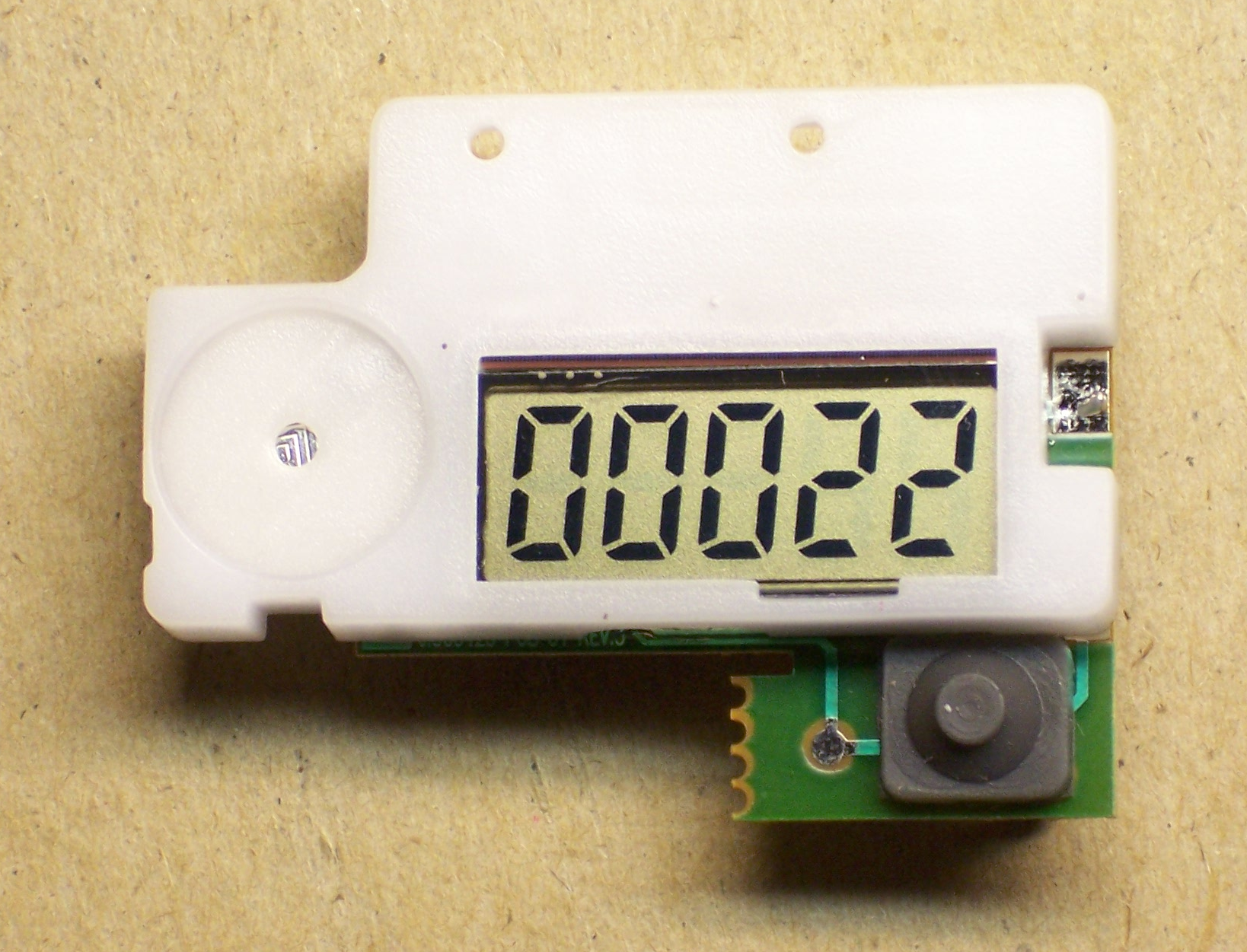
Look what my wife found in a Rice Krispies box!

It’s a five-digit counter module! Oh, it’s supposed to count your steps while you walk around at Disneyland, but why shouldn’t it be able to count other things???
Okay, let’s do it.
Digging In
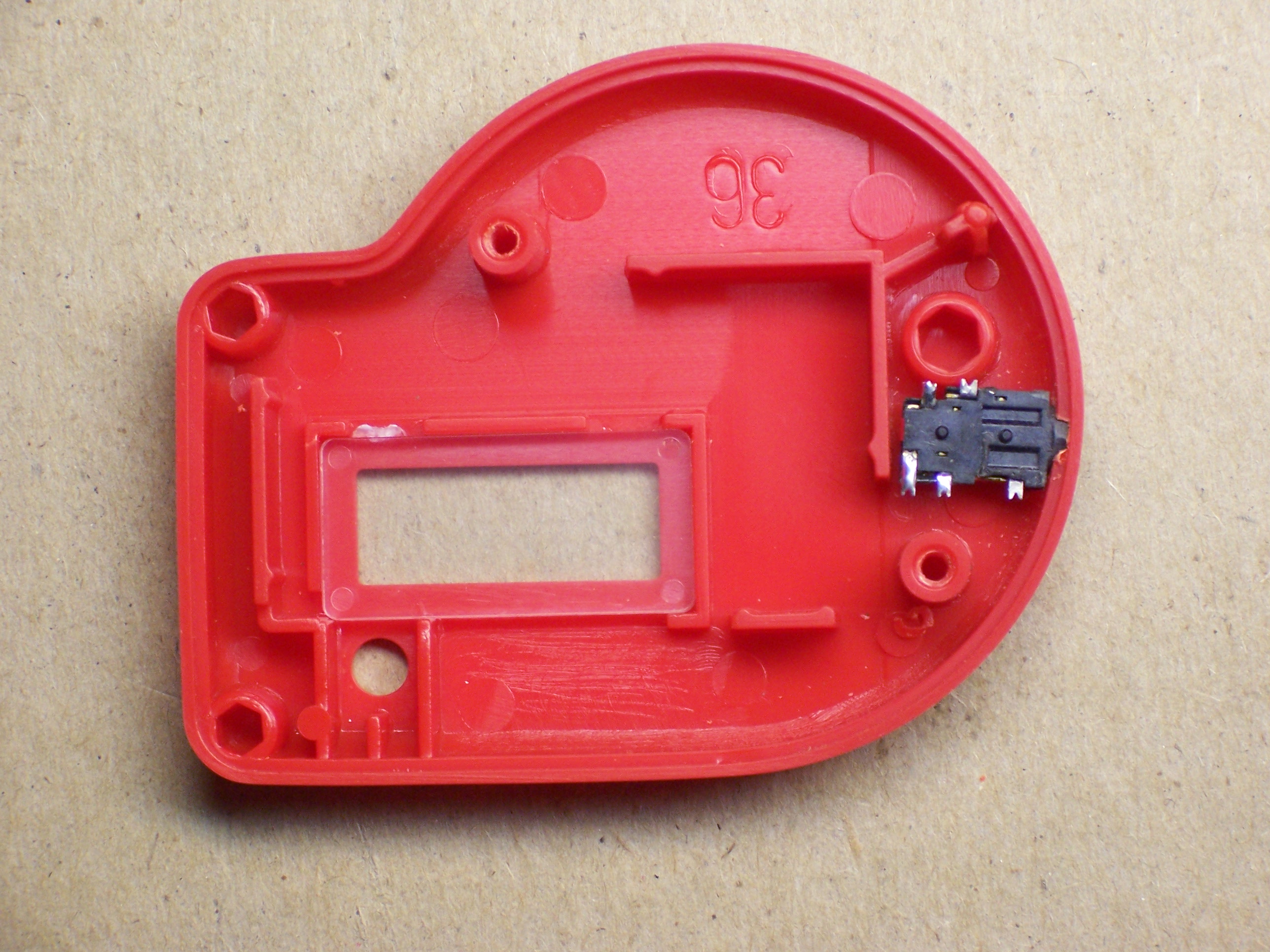
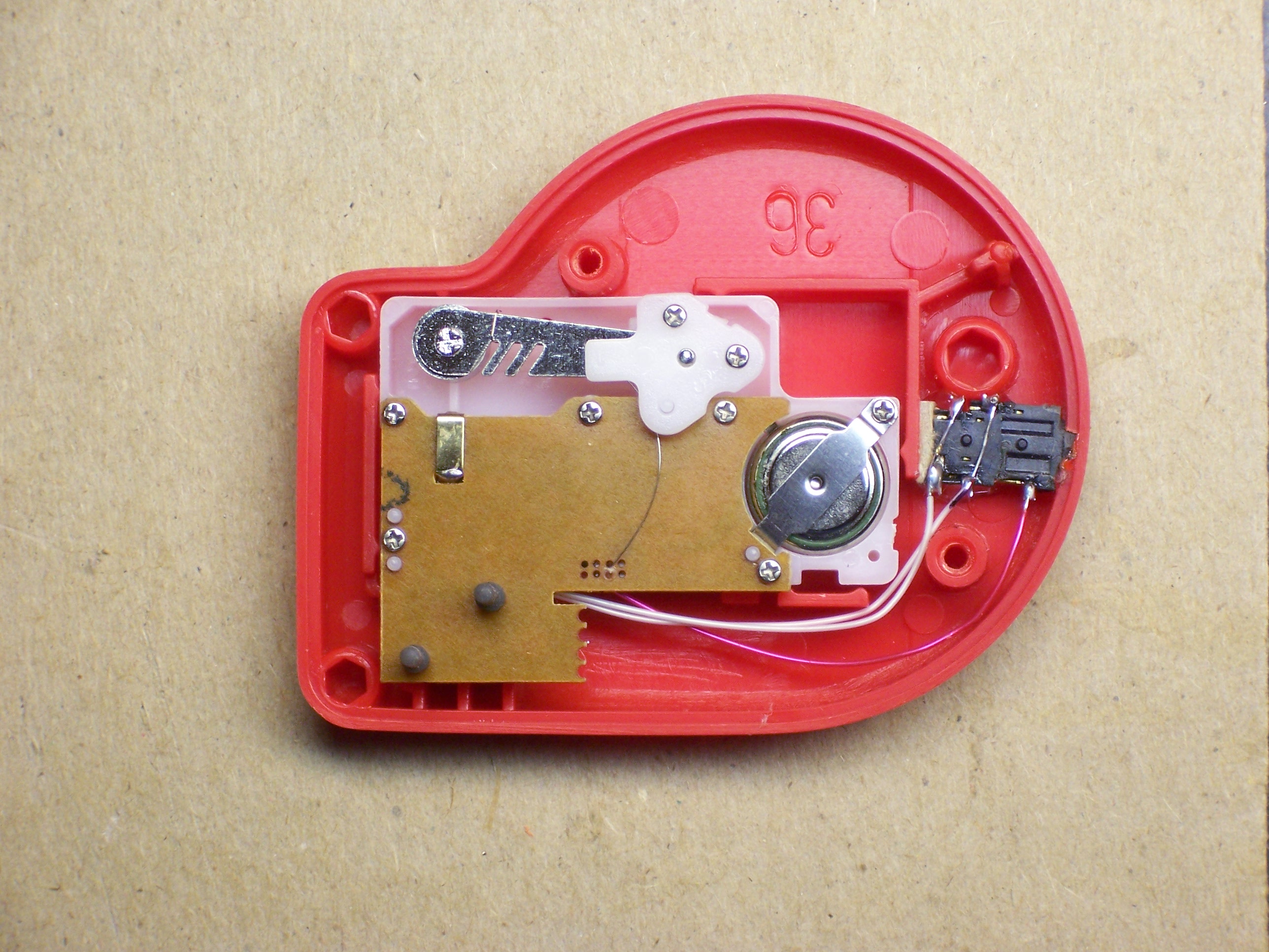
Here’s the back side of the case.
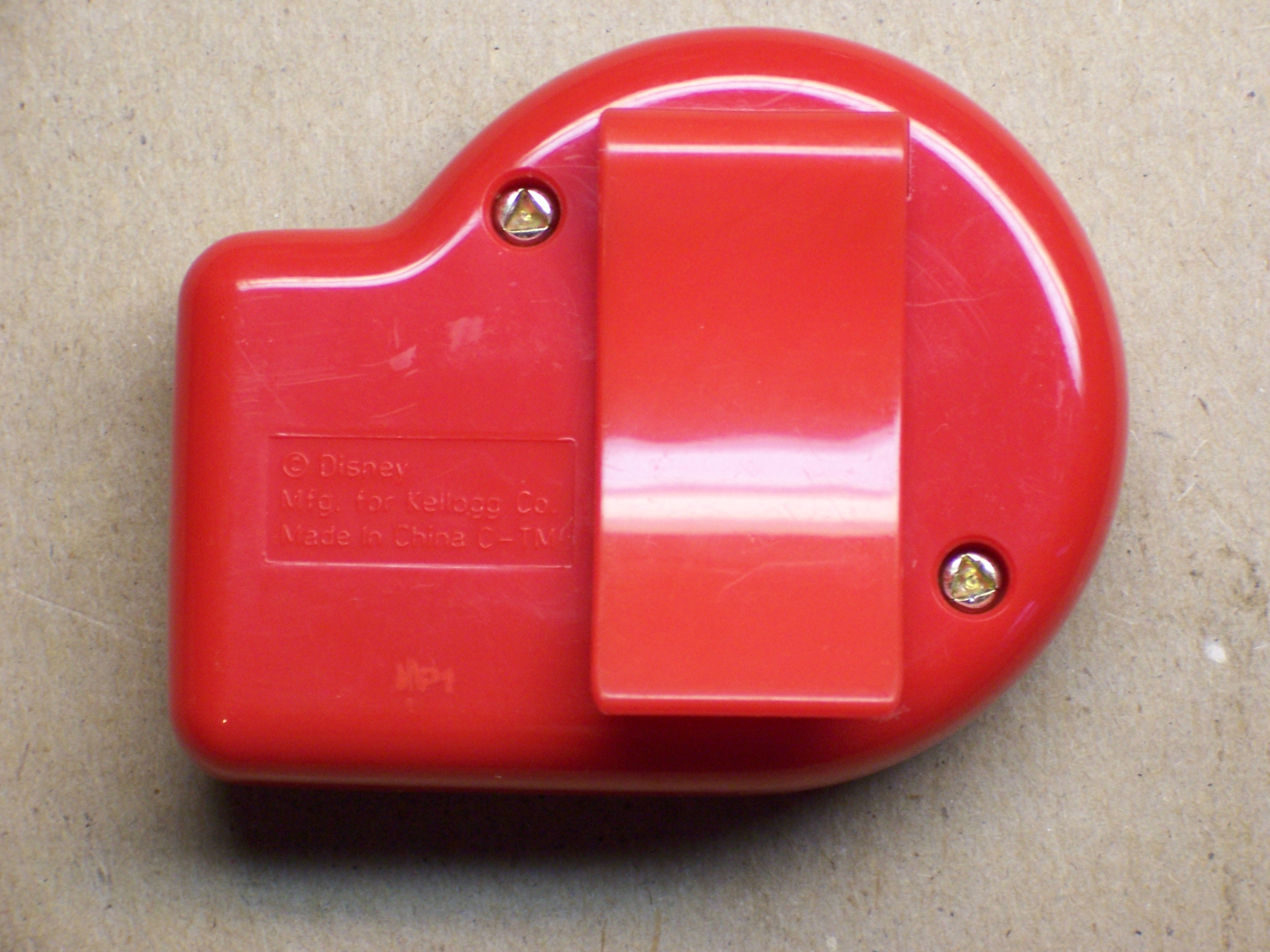
OH NOES!!! Triangle-drive screws! Whatever shall we do???
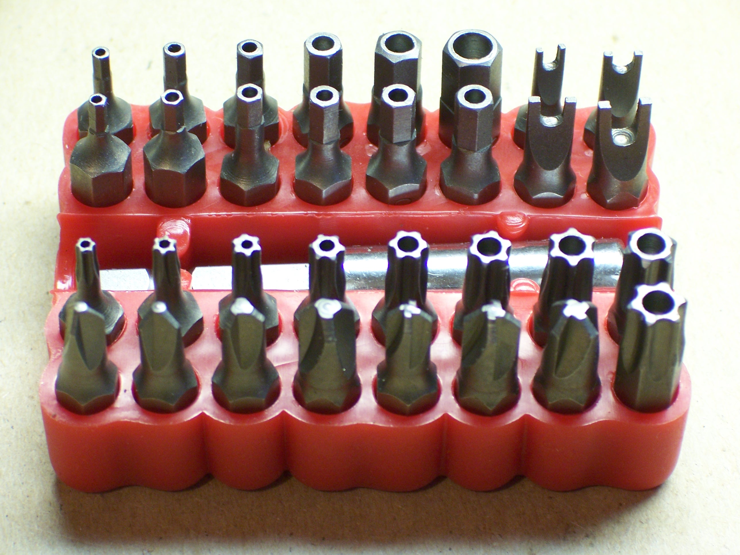
![]()
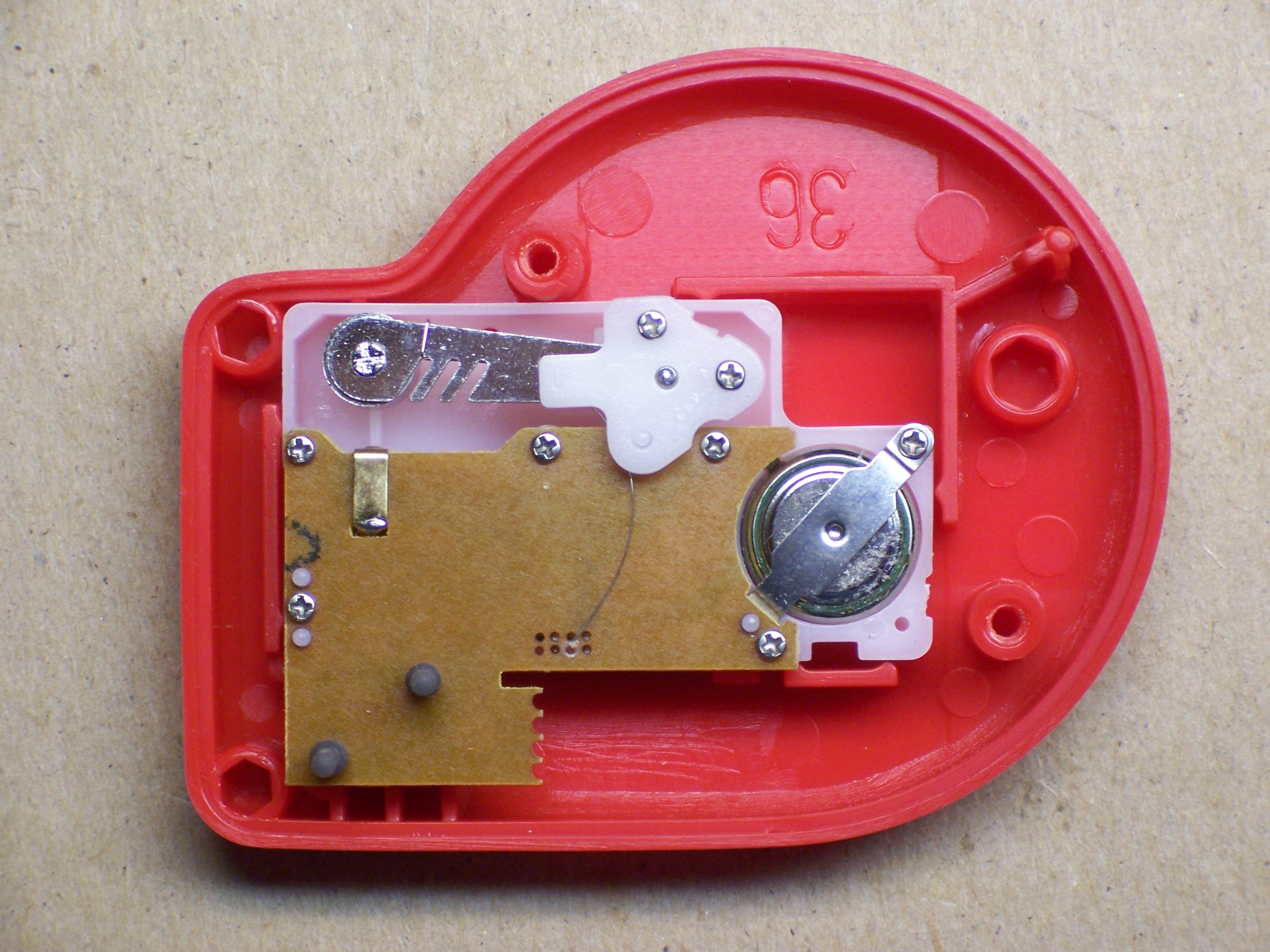
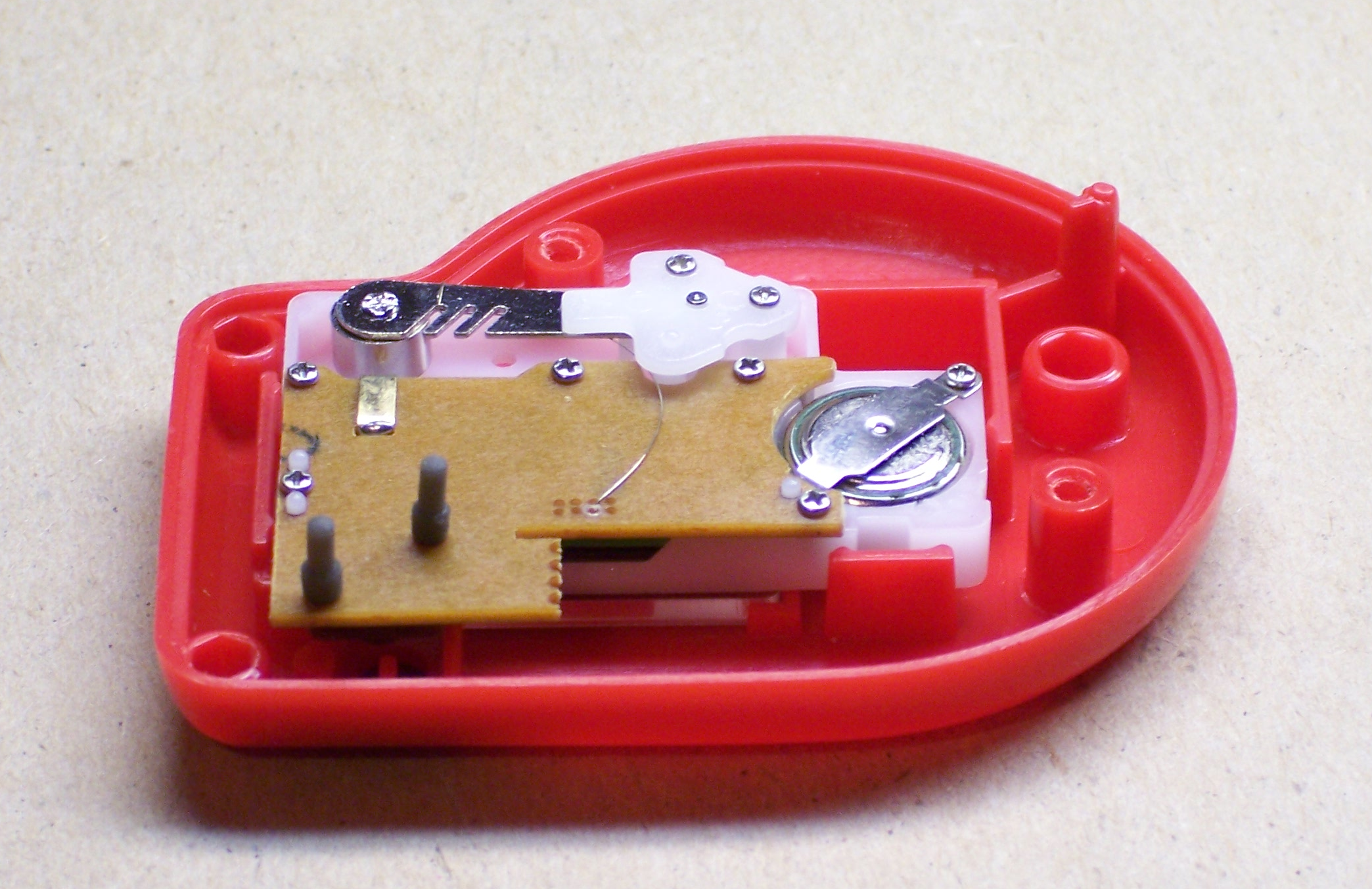
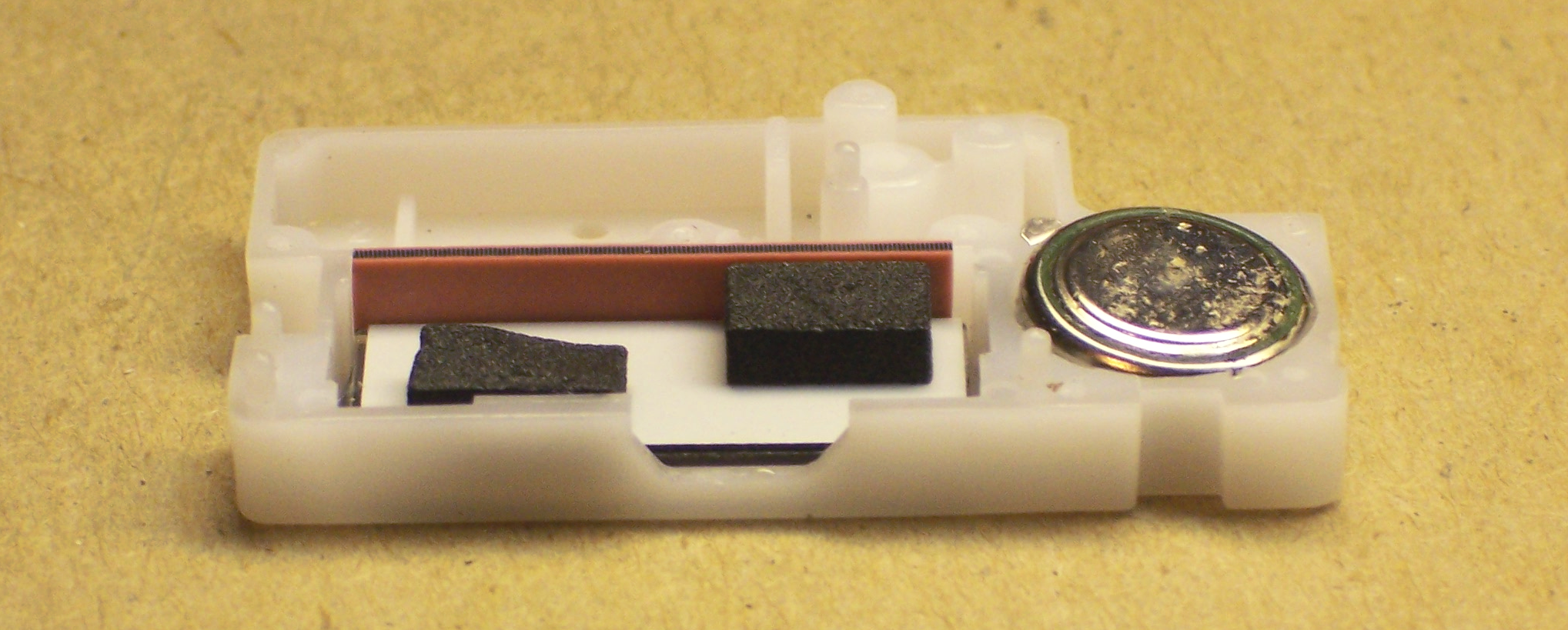
Here’s the inside. The metal arm at the upper left has a small weight, nearly balanced by the hairspring. It bobs up and down when you walk, making contact on the downstrokes with the metal tab at the corner of the PC board.
The Guts
After removal of the two screws holding down the weight, the active electronics pop out–still running.
Disassembling the screws from the back of the PCB enables it to be separated from the screen.
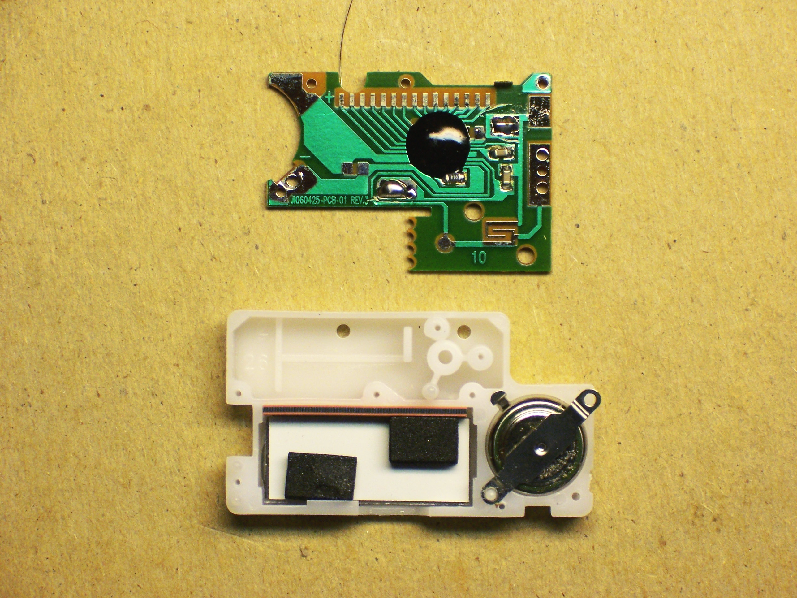
Note the anisotropic strip on the LCD. It looks like a strip of rubber, but conducts electricity only in the direction of its width (which is oriented vertically here). It interconnects the display contacts on the PCB with the contacts on the LCD, just by virtue of being squeezed between them.
Mickey, Meet Jack
It’d be nice to be able to continue using this as a pedometer, but connect something else to count. And it’d be nice if connecting something else disabled the internal counter so you didn’t get extra counts from bouncy bouncy, right?
So we need a closed-circuit jack. It feeds a default signal to the destination, and disconnects the default when you plug something in. Think of plugging headphones into a receiver and it shutting off the speakers . . . or plugging a headset into a cell phone and it disabling the built-in earpiece and mike.
[A few frustrating minutes with a good soldering iron and a bad piece of solder wick later . . .]
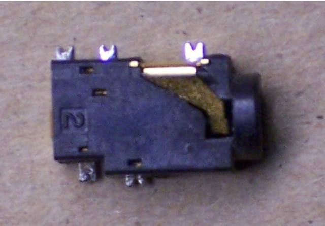
The jack. Or in French, Le Jacques.
According to my continuity meter, the connections closest to each other on each side are normally closed (NC), and open to break the connection when a plug is inserted. The ones nearest the plug end make connection with the plug, and the ones furthest from the plug end get disconnected.
This jack is made for a stereo plug (common plus two wires), but we only need mono (common plus one wire). Which of the contacts touches the tip, and which the sleeve? I don’t know! We’ll connect both!
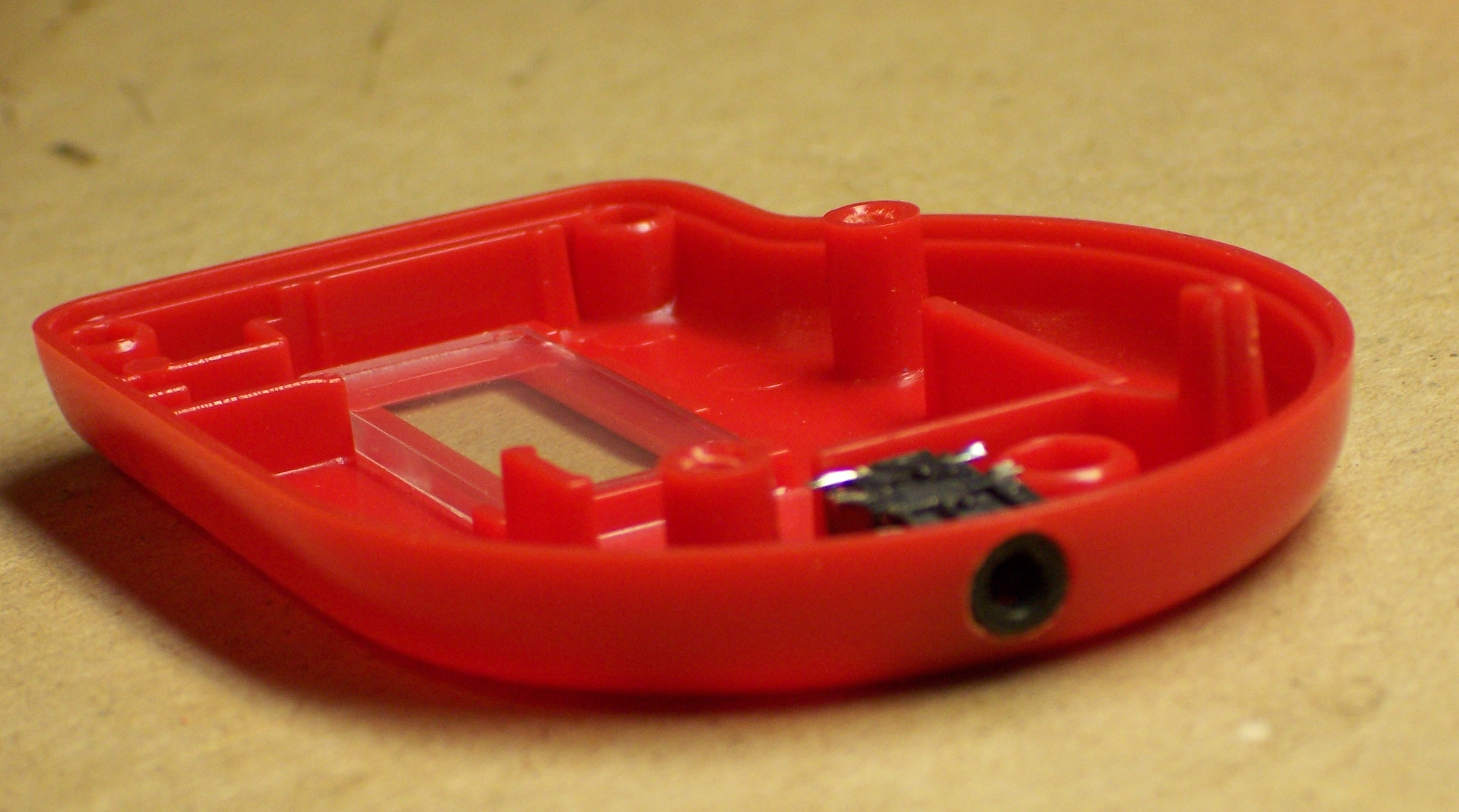
Hold. Mark. Drill tiny. Enlarge. Enlarge. Enlarge. Step-drill. Step-enlarge. Step-enlarge. Voila! Or in French, voila!
Mickey, Meet Wire
Hum tiddle-um, time to do some wiring. Need to break the connection on one side of the weight-switch and reroute it through the default (NC) pins on the jack. The big metal strip that the weight hits is pretty directly connected to what turns out to be the + power lead, so it’s easier to interject into the hairspring’s connection (the big solder blob in the lower middle).
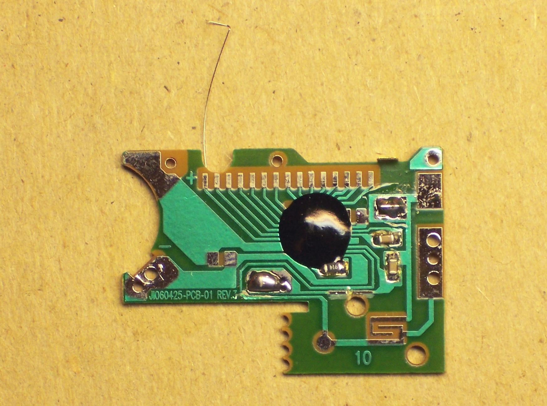
Scrape, scrape, scrape, scrape, scrape. Clean the green varnish off the trace. Then cut the trace (just above the mounting hole).
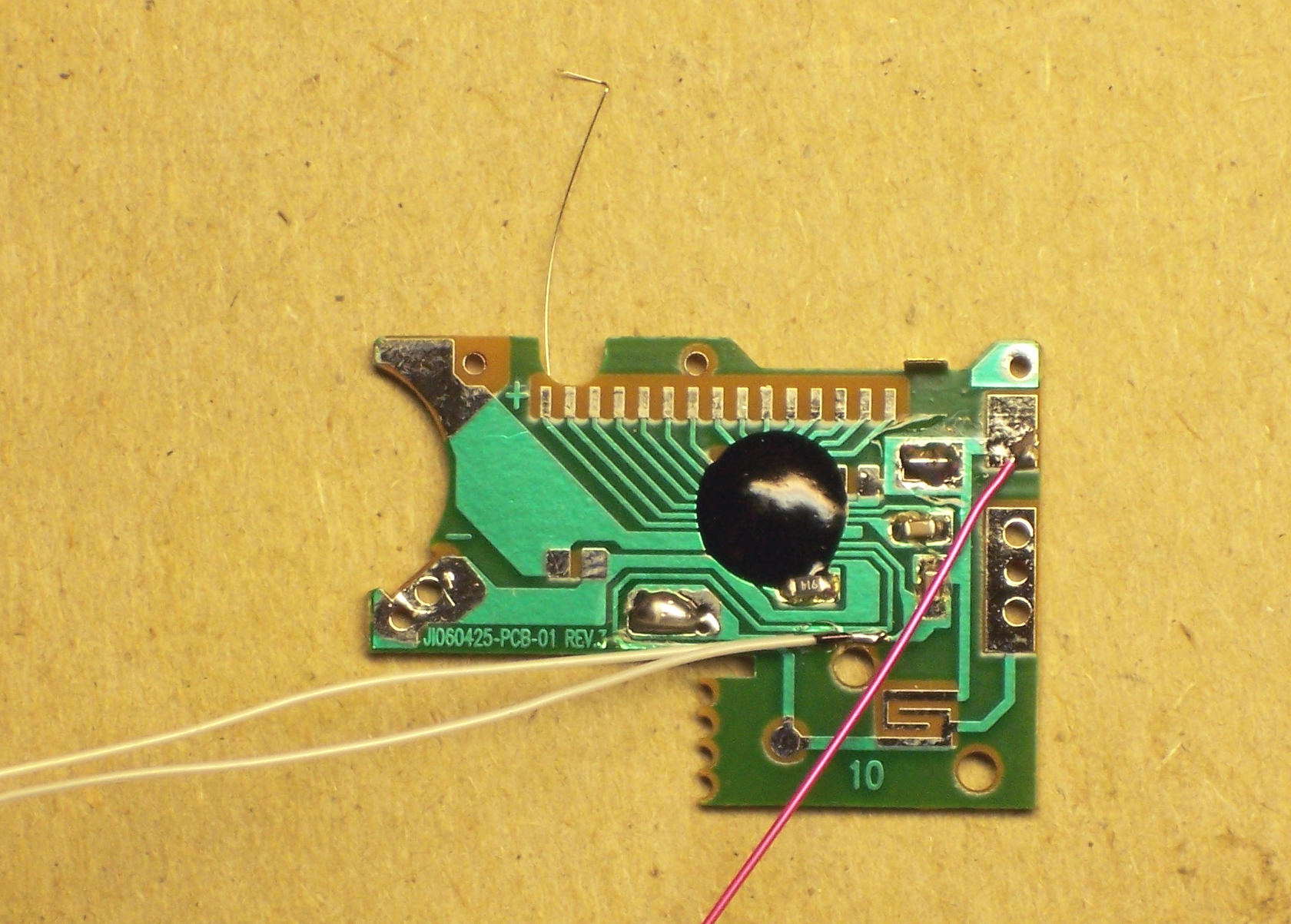
And solder on some fly wires to go to the jack. I knew that my leftover wire wrap would come in handy someday. One piece to each side of the cut trace, and one piece to the + power supply (to take the place of the weight switch).
After some notching of the LCD case (more than was intended, thanks to lack of planning), the module can be closed back up. I highly recommend putting the battery connector in the wrong place, so there can be more takey-aparty and putty-back-togethery. Then wire to the jack, connecting to both sides as mentioned earlier. (See the bare wires running across the left end?)
Or in French, Voilalala!

One completed, rewired, general-purpose, five-digit decimal counter.
The anisotropic strip on the LCD is technically known as an elastromeric connector, but usually referred to as a zebra strip. If you examine it closely under a strong magnifying glass or a low power microscope, you’ll see alternating bands of conductive and insulating material, usually something like graphite loaded rubber for the conductive material and unloaded rubber for the insulating material. The graphite loaded rubber gives that portion of the strip a darker colour. Thus, you have alternating light and dark bands, similar to what a zebra looks like.
Dave
So what else besides steps are you going to count? Your audience wants to know! : )
What to count with it is actually an interesting question. When I was converting it, I actually had something in mind — turns of wire on a coil-winding machine, to make a custom pickup for my home-built solid-body electric viola. (That’s a whole ‘nother story for a whole ‘nother time, when I get it all finished.)
People have hacked old sewing machines to wind coils, and I figured I’d put a bump on the axle, trigger a microswitch or optointerruptor every time the axle turned, and count the turns with this counter. As it turns out, I’ve found it can only count about 2-3 steps per second, possibly by design.
Meanwhile, my wife is on the board of directors for the annual city festival, and needed a people-counter for the park gate she was staffing. I hot-glued a momentary-contact pushbutton to the case, wired up a plug cut off a cheap (and dead) cell-phone headset, and gave her a serviceable (but ugly) pushbutton counter.
I’d be happy to take suggestions for other things to count . . .
Keith,
I have a requirement for a low cost, low power LCD counter which needs to count down as well as up ie: from two separate inputs. Can a cheap counter like the one you’ve shown in your ‘Rice Krispies 5 digit counter’ article be configured to do this?
Regards
Paul
UK
Paul, that’s a good question. I’d be a lot better equipped to give you an answer if the counter chip weren’t hidden inside a blob of epoxy, and I could read the part number and look up a datasheet.
Looking back at my pictures, it’s not obvious to me whether there’s another line that could possibly be a count-down input — I’d have to look at it in real life again for a bit. But I kind of doubt that it has that functionality. And I doubt even more that anything I’d learn about this counter would apply directly toward another you might find.
If you can tell me a little more about your application (how low cost and how low power), I have a couple of other ideas that might work for you.
Keith,
I am trying to construct a cheap digital positional display. Imaging if you needed to know the position of something and you where tracking it so that every time it moved in one direction or the other the display informed you of its current position. I have achieved this with a 3 seven LED display using a home made ‘pulse wheel’ (encoder) which creates pulses in either direction via two photoerupters which are my inputs to a CMOS up/down counter circuit. I would prefer a cheap LCD solution and this thing needs to be battery powered so I’m concerned about battery life. I am certainly not an electronics boff. You may recommend that a PIC’s microcontroller is the best solution for this type of application (of which I know very little)
Regards
Paul
UK
Hello, Keith,
Did you ever write that post on your pickup winder? I don’t seem to find it.
I’m in the process of building a coil winder myself for guitar pickups and I’m a bit lost concerning the counter. I don’t have such a toy around here, just a few calculators but I would rather take a more elegant approach and build a 5 digit counter myself – I’ve spent the last few hours doing some research and your post got my most attention. Would you be willing to advise me on building this counter, please?
Lev, no, I’m sorry, but I haven’t got to the pickup winder.
Do you want something that would count both up and down; so if you had to unwind some loops it’d count them backward?
I’m thinking of something using a hall effect or optical sensor and actually building it with discrete TTL BCD counters and seven-segment drivers. I love the cachet of using old-school digital logic, but here I think it actually even makes sense.
Keith,
Yes, it would be wonderful if it could also count backwards.
I will look into your suggestion, it all sounds new to me. I’ve been looking into motor speed controllers in the last few days.
Could you contact me via email? I won’t take much of your time, it’s just that being new at this, I still have some questions even after doing research. It would be really helpful.