Archive for May, 2010

MIDI Looper?

Monday, May 31st, 2010

I’m starting to think I’d like a MIDI sequencer that behaves somewhat like a looper, doing the following:

  • Capture a short sample of a MIDI performance, including key velocity data.
  • Quantize to a tempo set by a “tap tempo” pedal continually and dynamically throughout the capture, rather than to an LED or click track.
  • Loop and play back, by default to the last tempo seen but honoring continuous “tap tempo” data from the same pedal.

Using a MIDI sequencer with these “tap tempo” features should give greater flexibility for capture and playback during a live ensemble performance than using a traditional audio looper, which requires the whole ensemble to play to the tempo recorded in the loop.

But my real motivation is to be able to play a pattern and then make gradual, multi-bar changes to the analog character of the sound without having to continue playing with one hand and turn knobs with the other.

Record a one-bar pattern on a MIDI keyboard driving a x0xb0x (or a real TB-303, if you’re filthy rich enough to have one and a DIN-sync MIDI adapter to go with it), then play it back and slowly tweak the knobs while everyone else jams on for a bit.

Am I going to find that all of this functionality already exists within the x0xb0x? (It looks like it might be close — MIDI ports; internal sequencer; variable tempo, although perhaps not that sophisticated.) Alternatively, are there MIDI sequencers that do all of this? Is this de rigeuer for every sequencer under the sun?

Repairing a Patch Cord

Monday, May 31st, 2010

Recently a couple of pieces of audio processing equipment I’ve bought used have had bad left channels. After recognizing the pattern, I finally thought to swap out the patch cord I had left plugged into the “test” channel on my keyboard mixer, and voila! Left channels fixed.

Audio patch cord, disassembled

I’ve always been curious about the construction quality of commercial patch cords — just how good are the connections buried under those lovely molded jackets and strain reliefs?

Naturally, the faulty end was the last one I disassembled. (Logic joke!)

(more…)

EasyBright on Stage

Tuesday, May 25th, 2010

Music stand wand light with lens flare

Saturday night the EasyBright already got its public debut! I played a pair of classic rock concerts Friday and Saturday nights, and Friday had trouble seeing my music (occasionally folded out to four pages) with the clip-on stand light I was using. Saturday after assembling the EasyBright, I built an LED “wand” music stand light that worked marvelously.

End of LED wand music stand light

I didn’t have a lot of time for construction, so I cut a 1/2″ dowel to 3′ length and drilled eighteen 1/8″ holes through it (axially, not longitudinally) every 2″. Paint wouldn’t dry before the show, so I sanded the dowel and then colored it with a permanent marker. I then installed bright flat-top LEDs with a good viewing angle into the holes and bent the leads out in opposite directions.

Wiring on LED wand music stand light

I lap-soldered teflon-insulated (heat-resistant) wire from LED to LED with heat-shrink tubing preinstalled — but didn’t shrink the tubing until after I had tested the LEDs, in case I needed to repair any solder joints. I skipped LEDs to make an A-B-C-A-B-C pattern so if a chain failed, I’d lose light evenly along the whole wand instead of all in one section.

Connectors at end of LED wand music stand light

I crimped connectors onto the wires, connected everything to the EasyBright, put an appropriate connector on a 24VDC wall wart, and fired it up perfectly on the first try. (Such luck!) I disconnected the wand, reseated and shrank the heat-shrink, zip-tied the wires in place, and then powered up the wand to burn in for an hour before leaving home for the concert.

LED wand music stand light

On stage, it delivered a very even wash of illumination across my music, giving me a great view all through the show.

EasyBright circuit board driving LED wand music stand light

The circuit board is so lightweight, it was comfortably suspended in mid-air between the keyboard rack and my music stand by the power and LED wires. For the long term, I’m trying to decide whether how it should be mounted to the wand — perhaps attached near the end inside a sleeve of giant heat-shrink.

MakerBot CupCake Aluminum Idler Wheel and Printing in Plaid Due to Motor Shaft Deflection

Tuesday, May 25th, 2010

Aluminum idler wheels for MakerBot CupCake

At the end of March, I broke my MakerBot CupCake idler wheel while trying out my new filament drive worm-pulley. In April, my friends Scott Smith and Ben Wynne in San Diego machined me some aluminum replacement wheels, which are totally awesome.

Broken acrylic and replacement aluminum MakerBot CupCake Plastruder idler wheels

Old and busted; new hotness. Yeah, baby!

This wheel press-fits perfectly onto the bearing, starting by hand and then leaning heavily on it on a countertop. It’s thicker than the original wheel, making precise alignment with the drive pulley less important. It even has a knurled edge — showoffs!

Plaid print from MakerBot CupCake

I’d been experiencing “plaid” printing, in which the filament feed rate dropped at very regular intervals, and attributed it to the (tangible) irregularities of the acrylic idler wheel. But I’m still getting plaid prints, and I don’t think my aluminum wheel (hot off the lathe) is irregular, so the problem must be elsewhere.

MakerBot CupCake filament feed

Hm, look at the deflection of my filament feed motor shaft, all the way to the left of the hole in the enclosure.

MakerBot CupCake filament feed

Hm, look at the deflection of the shaft now, when the flat hits the edge. That would explain why the weak feed is so regular — recovery doesn’t rely on the drive pulley maybe grabbing the filament and maybe being able to spin the idler wheel to a different spot before it gets going again.

Looks like I need a bearing on that motor shaft. I printed a shoulder washer/bushing for it and it helped for a while, but not enough. I think a real, metal bearing is in my future. And perhaps a different drive geometry. A lot of good filament feed designs are being uploaded to Thingiverse.

Assembling the first EasyBright

Tuesday, May 25th, 2010

EasyBright components

Last week while watching Mannequin (a very young and fresh Kim Cattrall, a goofy plot, and music by Starship — what could be better? okay, if it had John Cusack and were set in Shermer, Illinois, yes, that would be better) I split all the EasyBright components into a parts bin for easy access and portability.

Saturday afternoon I put together the first sample.

EasyBright-3L constant-current LED string driver PCB with solder paste

This is waaaaaay too much solder paste for 0603 parts and 1/40″ IC pin spacing. I had to remove several solder bridges from the IC, and the passives had solder mounds instead of fillets. I took the picture specifically to record how much paste I used so I could adjust on the second attempt.

EasyBright-3L constant-current LED string driver, front

Here’s the cleaned-up board, front side.

EasyBright-3L constant-current LED string driver, back

Back side, with hand-written labels for the current rating and the serial number (S00). The “permanent” marker comes off easily with rubbing alcohol — I need to get some clear nail polish to seal it in.

Changes

Even before assembly, I had made notes about (and started implementing) things to fix whenever I print the next boards:

  • Change the IC’s ground connection from a via outside the IC footprint to a trace going straight in to the heatsink pad. I had routed that connection before I confirmed with Maxim that the pad is okay to connect to ground — it’s just not okay to be the only ground — and then forgot to go back and change it. Removing that via gives me a little more room to route the bottom-side LED power traces cleanly, and also:
  • Increase the pad size on the optional through-hole current-sense resistors. This, believe it or not, is EAGLE’s default pad size, and I think it’d be challenging to solder without a good, narrow-tipped iron.
  • Increase the trace isolation on the solder-side ground pour. There’s no reason to have it that close to the pads.
  • More subtle, I spaced the 2-pin connector pads an extra .02″ apart to see whether I could get the connectors to friction-fit for ease while soldering. They don’t quite. Either change the library footprint to space the pads a little further apart or just get used to pinching the leads together before stuffing the parts and soldering, which works better than I had expected.

I’m still delighted!

x0xb0x Box!

Monday, May 24th, 2010

x0xb0x synthesizer kit, Willzyx edition

My x0xb0x kit has arrived from Taiwan!!!

x0xb0x synthesizer kit, Willzyx edition

Gold Phoenix for EasyBright PCB Manufacturing

Monday, May 24th, 2010

Two and a half weeks ago, I finished up the CAM files for my first set of EasyBright LED driver PC boards and sent them off to have boards made.

PC board order from Gold Phoenix

While shopping around for board houses, I had narrowed my choices to two. Here’s how I made the final selection of Gold Phoenix — not, as it turns out, whom I thought at first I was going to pick.

(more…)

Replacement Headphone Cables?

Thursday, May 20th, 2010

I have a whole box of what I believe to be moderate- to high-quality over-the-ear headphones with worn-out, shredded cords.

Anyone know a source for replacement headphone cables, preferably straight (not coiled) with 1/4″ plugs, and absolutely with supple cable and alreadying Y-ing out to both ears? 6′ cable would be okay and 10′ would be fantastic.

Viewing PCB Gerber Files Before Manufacturing

Thursday, May 6th, 2010

I’ve spent my last week and a half’s free time going back and forth among EAGLE, eagle3d, 1:1 printouts, and the Viewplot Gerber viewer. That’s how long it took me to get the silkscreen layer tweaked to my satisfaction — which I completely didn’t anticipate.

Thank you, thank you, thank you SparkFun for emphasizing how important it is to view your Gerbers before submitting (search in page for “Something I highly recommend”).

eagle3d view of LED driver prototype

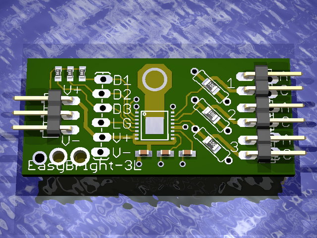
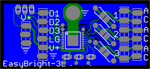
I had already rendered the board layout in eagle3d (pay no mind to the test holes I used to figure out that eagle3d doesn’t make holes through copper that’s part of a polygon, which its documentation clearly states if you bother to read it) and thought it looked pretty good.

But I followed Nate’s advice, installed Viewplot, and was rather startled to see what my board was really going to look like.

Viewplot Gerber view of LED driver prototype

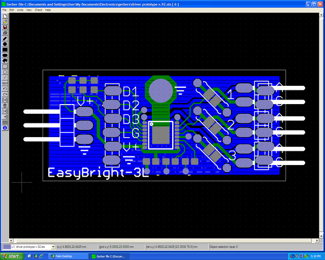
The silkscreened boxes for the plastic “keepers” on the pin headers are fairly faithful to the connectors I’m using, but what’s with putting the pins in the silkscreen? I don’t need a shadow of the pins on the board.

Also the 0805 SMT resistors and capacitors don’t have silk around them showing which pads belong to the same component. It’s easy enough to figure out on this small board, but I’d like to develop good habits.

EAGLE CAM processor showing layers going into top-side silkscreen

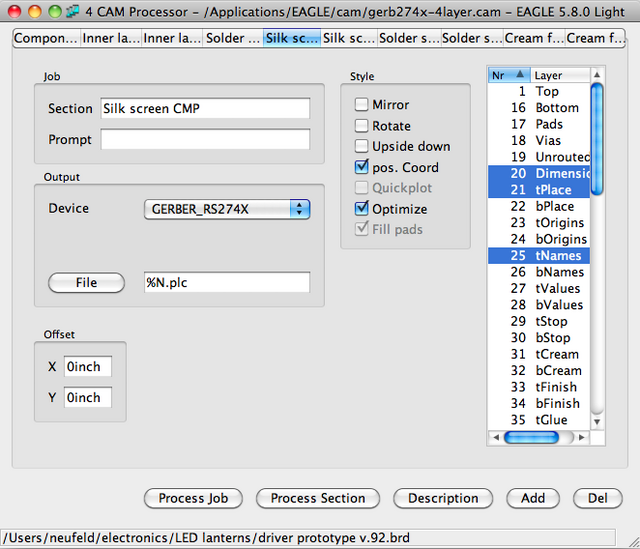
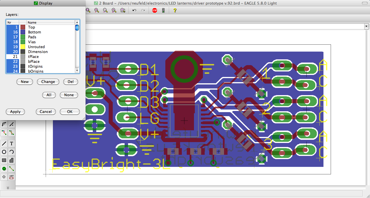
EAGLE’s CAM processor lets you pick which PCB layers are used to generate each Gerber file, and there’s not much in my top silk layer. The pins must be in tPlace, so I used the PCB layout editor to preview what would happen if I turned it off …

EAGLE PCB layout with tPlace layer switched off

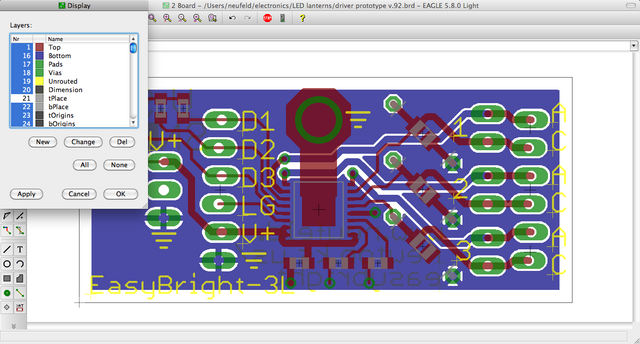
I lost the header outlines as well as the pins, as well as the outlines for the optional through-hole resistors. That’s not gonna work.

Changing package of two-pin connector in EAGLE PCB layout

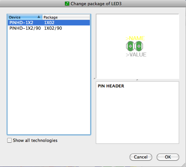
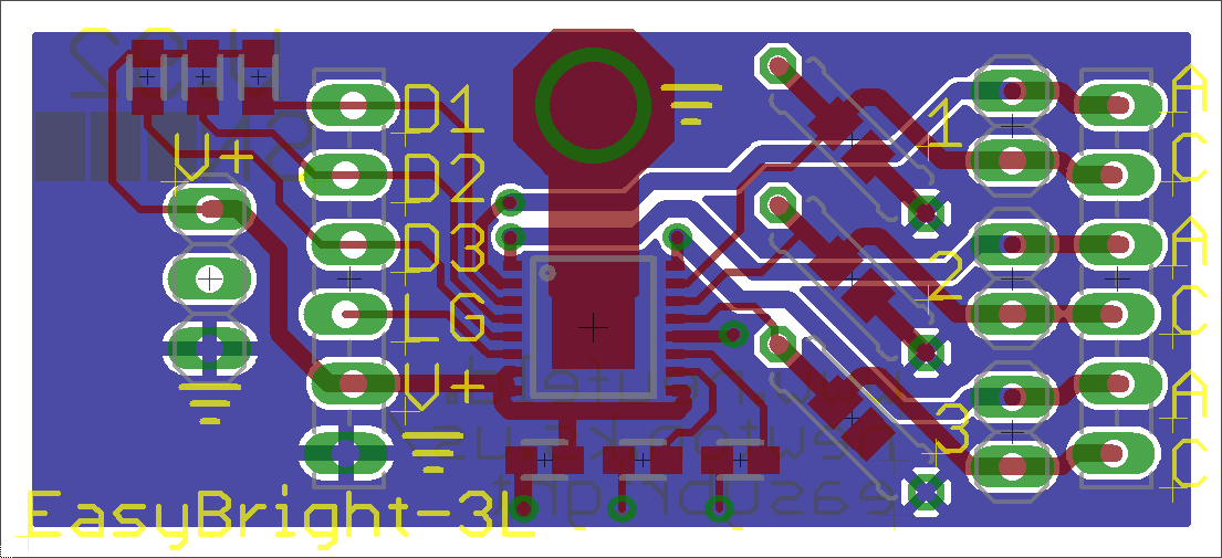
Exercising outrageous optimism, I tried changing my header packages from right-angle to vertical, hoping they’d have more appropriate package outlines (still in the tPlace layer).

EAGLE PCB layout with header type switched, tDocu on

Better — no stray pins in the silkscreen. Now guardedly optimistic.

EAGLE PCB layout with tDocu off and supplemental silk drawn in tPlace layer

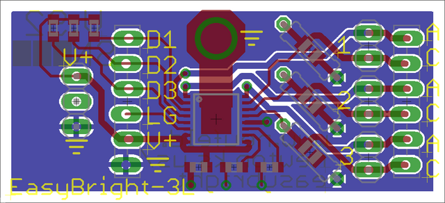
I turned off the tDocu layer that shows the physical outlines of components, and which isn’t (and mustn’t be) included in the silkscreen Gerber because it would interfere with soldering, then added lines in tPlace to indicate the edges of SMT components.

Silly me — I thought I was done!

Viewplot Gerber view of revised LED driver prototype

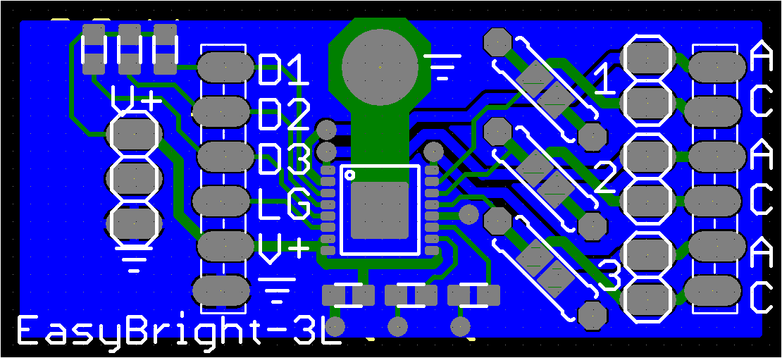
Back in Viewplot, look at how the silkscreen around the power connector is now crowding the pin labels. Aaargh! There’s not room to move them far enough away.

Viewplot Gerber view of revised LED driver silkscreen

I went back to my connector library and designed two- and three-pin versions of “locking” connectors based on the SparkFun locking connector concept. (See footnote about SparkFun EAGLE library license terms.)

The Gerber view looked pretty good now, except the ground symbol was too close to the power header and a little visually confusing.

Viewplot Gerber view of LED driver with working drill holes

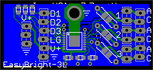
I moved that down a bit and in my next trip to Viewplot discovered how to get the drill holes to show up: don’t load the drill rack file into Viewplot, just the drill file itself. Getting visualization with holes and confirmation that there’s really a mounting hole through the heatsink — outstanding!

Somewhere around this time I also printed out the solder-side of the board to make sure that the boxes I made to write in (visible in the next screen shot) were large enough for me to write in. They weren’t. I enlarged them.

Done now, maybe?

Viewplot Gerber view of LED driver with working drill holes, back

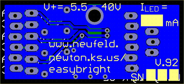
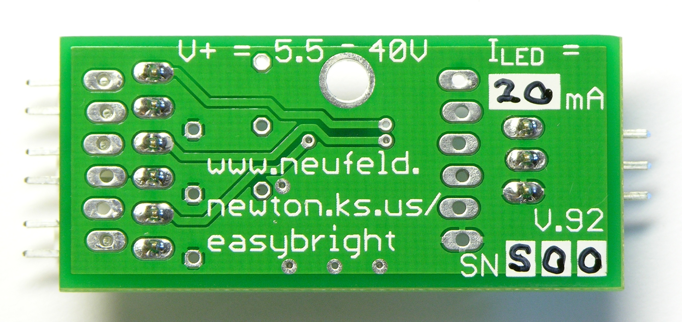
Oof, look at all the problems with the silkscreen on the back side. The top line looks like I’m incrementing V by 5.5-40V (C joke), and if I fix that I need to move ILED‘s = further away also. The / in the URL is awfully close to the solder pad, and the box for me to write the “factory”-configured LED current could stand to extend a little closer to the “mA” label.

Props to Nate at SparkFun again (search in page for “Label everything, all the time”) for reminding me to put the input voltage range and output current rating on the board, BTW.

Viewplot Gerber view of final LED driver design, back

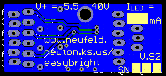
Fixed! Really! Done! If I stare at this thing any longer, I’m going to start hand-kerning the vector font.

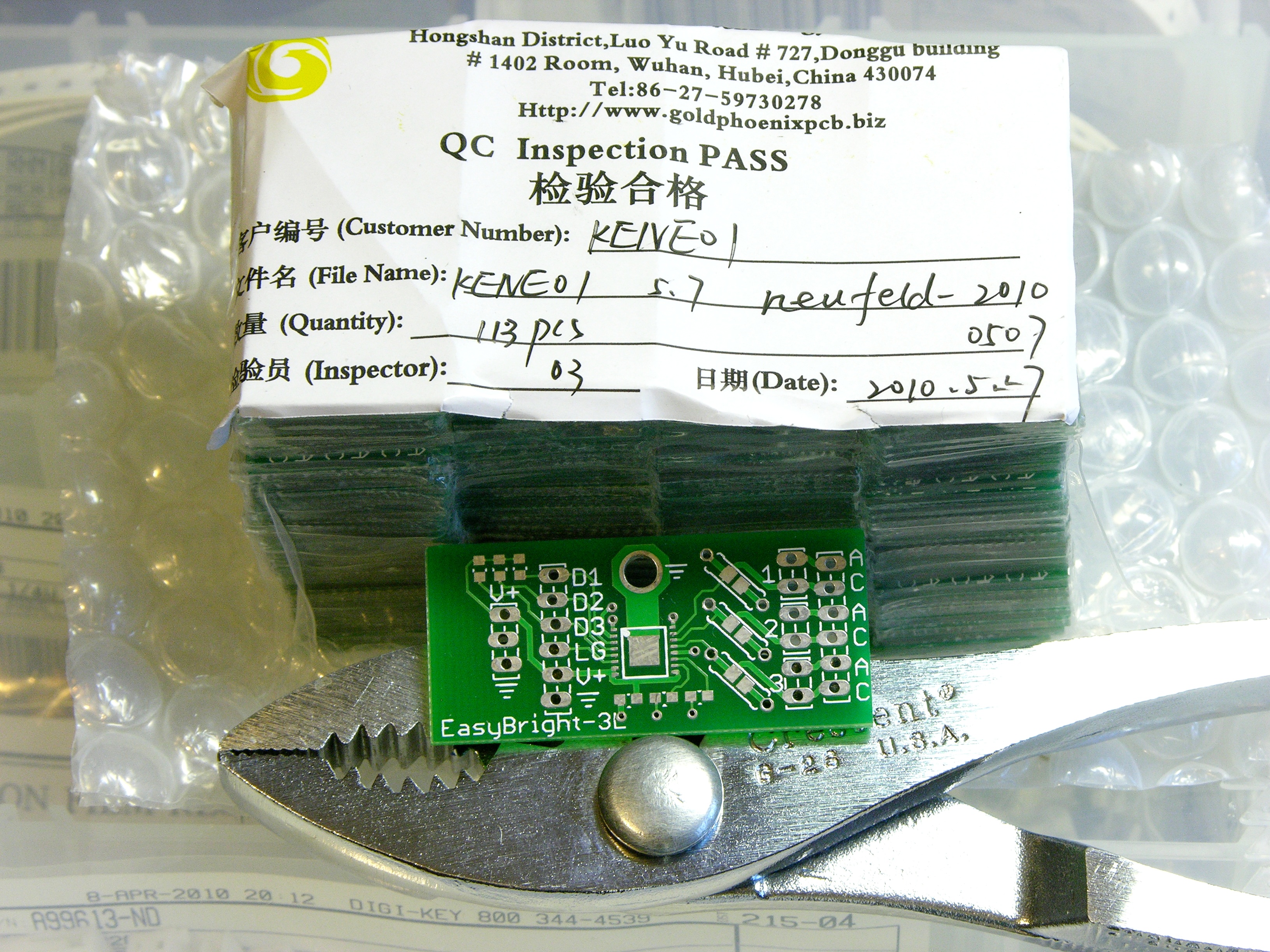
I zipped the files and uploaded them to Gold Phoenix last night.


SparkFun EAGLE Library License Terms

I’m not using SparkFun’s EAGLE library nor a derivative of their library file because I haven’t got a response from them whether their cc-by-sa license is intended to be:

  • like the GPL, meaning that if you use their library in your board design you have to open-source your whole design — which I will do after I’m confident the design is right but not immediately upon shipping — or
  • like the LGPL and you can use the library in your product without open-sourcing your design but you would have to open-source derivatives of the library itself.

So my connector library is most definitely based on Pete Lewis’s idea to skew pin positioning from side to side to make a header friction-fit in a board for soldering, but (as far as I know) the idea is not patented and I’m in the clear. My library is a reimplementation from scratch of the idea, so is not derivative of their library.

I hate playing games like this and I would love to toss my library and use SparkFun’s if I can get a verdict from them on the licensing. Also as soon as I’ve got boards tested and working and I’m ready to publish the design files, I can switch back to their library too.

Update 07-May-2010: I heard back from SparkFun and it will be fine for me to use their library. I’ll look at switching back on the next iteration of the board.

Glastherm HT Insulation with Glass Standoffs for Hotplates

Monday, May 3rd, 2010

As I discovered a couple of weeks ago, Glastherm HT is not a good enough insulator to protect the acrylic mounting plate under my MakerBot CupCake heated build platform. Last night I tried it with glass standoffs between the hotplate and the Glastherm.

Glass feet taped to underside of MakerBot CupCake heated build platform

I had some leftover glass from having a window cut recently. I bought a glass cutter and cut a half-inch strip off the end of one of the pieces, then cut that into smaller tiles. I smoothed the sharp edges on a diamond file, then pried apart the hotplate sandwich and stuck the glass tiles onto the leftover kapton tape.

Checking insulating value of Glastherm plate on glass standoffs under MakerBot CupCake heated build platform

I repeated my earlier test, standing the sandwich on edge on another piece of insulating material and running the heated build platform up to (and past) operating temperature. (Sorry no laser dot in the picture — I’m not quite coordinated enough to hold the thermometer’s capture button, point it the right direction, hold my hand still, and take a picture all at the same time.)

Plate Temp Back Max Temp Back Min Temp
120°F 85°F
145°F 95°F
175°F 120°F 105°F
Approximate CupCake target temperature
220°F 155°F 135°F
310°F 200°F

The air gap did a considerably better job of insulating than the Glastherm alone. Also when I remembered to measure the temperature separately under the glass feet, the spots were 15-20°F hotter than the rest of the Glastherm, suggesting that smaller glass dots could provide a significant further reduction in heat transfer.

Testing Glastherm insulation on glass standoffs under MakerBot CupCake heated build platform

135°F on the back side is pretty manageable; 200°F is a bit warm to be in contact with plastic. However, as Leon pointed out last time, it’s not just about how hot the back side gets, but about how rapidly the heat is transferred into the backing material.

I set the heated platform onto a spare piece of plexiglass and also dropped some scrap filament onto the top of the platform. Already above operating temperatures, the filament softened nicely and the plexiglass stayed cool to the touch and didn’t warp. Leaving the setup unattended for a while and letting the platform drift up to 340°F, the plexi got a little soft.

I think this is usable for the CupCake, but I’ll need to exercise a little care managing the plate temperature (and I’m overdue hooking up the thermistor for closed-loop temperature control). I think this may not yet be enough insulation to tape my SMT hotplate directly on top of a plastic enclosure and run 290°C (~550°F) soldering temperatures.