Archive for April, 2006

Craft to Art; Construction to Exhibit

Wednesday, April 26th, 2006

Andrea’s doing an amazing job prepping the cabinet for display. While I was painting the primer, the cabinet looked white and ucky like this:

And here’s my wife helping on the first coat:

But bring it to someone with vision and you get a sweet-looking flat grey base coat on the outside:

And a “camel” color on the interior that really makes the coffin shape pop:

Andrea has also “bagged” (sponged) on some bronzing, which looks great:

And I can hardly wait to see the pink (fuschia?!) that comes next, with a crackle coat to follow. Sweet!

Ultrasonic Rangefinder, Part III: Receiver / LogoChip Interface Attempt

Wednesday, April 26th, 2006

I haven’t touched the DIY rangefinder project for a couple of weeks, but I realized I also never wrote up my latest work on it.

Receiver Comparator

After my previous post about building two amplifier stages, I intended to use one of the spare channels on the LM324 as a comparator to “digitize” the amplified receiver signal and provide a clean input to the LogoChip. Unfortunately, the first time I prototyped it was late in the evening when my brain doesn’t work too well, and I built it just like the first two stages–as a linear amplifier. I was really surprised to see more analog waveforms on my scope when I expected sharp edges. At only 24kHz, I didn’t think it should be a slew rate problem, but I wasn’t thinking clearly and just set it aside for the night.

The next day, my error was obvious, and I pulled out the feedback resistor to let the op amp run open loop with infinite gain. It cleaned up the signal, although still not as much as I would have expected. Once the basic circuit was working, I replaced the fixed voltage divider with a 20k trimpot and tuned it as well as I could, trying to find the sweet spot to weed out all the noise but pass all the real signals.

I hadn’t seen it before, but now I wondered whether I was getting some false readings from noise, as John suggested he had encountered when working on similar circuits. I looked briefly at adding a low-pass filter to the circuit (it’s already high-pass filtered by the capacitive coupling from the receiver to the first amplifier stage due to the single-ended op-amp I’m using), but haven’t done it yet. First I wanted to connect it to the LogoChip and see what kind of results I got.

PIC CCP

An ultrasonic rangefinder measures distance by emitting a “ping” and counting the time until the echo is detected; dividing by the speed of sound translates the round-trip time into a distance. Because of the short durations involved, the easiest way to do this on a PIC microcontroller is with the “capture” section of the Capture/Compare/PWM (CCP) subsystem. It uses a high-resolution timer and interrupt circuitry to give a very precise measurement of how long something takes to happen.

I started with John Harrison’s CCP code from his srf_demo.txt example on the TechArt wiki LogoChip with Ultrasonic Sensor page. His code was using the PIC’s CCP module #1; but in my application, I was already using CCP1 to provide the 24kHz signal for my transmitter, so I started translating to use CCP2. The control and behavior of the two CCP channels are rather different, so it wasn’t a matter of simple substitution. Here’s what I ended up with:

Here’s the receiver section of the code:

;------------------------------------------------------------------------------
;   Routines for manipulating CCP2 and timer 3 for capture.
;------------------------------------------------------------------------------

constants [
    [CCP2CON $fba]                      ;   capture/compare/PWM 2 control reg
        [CCPxM-CAP-EVERY #0100]                 ;   capture every falling edge
    [CCPR2H $fbc]                       ;   CCP 2 register low byte
    [CCPR2L $fbb]                       ;   CCP 2 register low byte
    [PIR2 $fa1]                         ;   peripheral interrupt request 2
        [CCP2IF 0]                              ;   timer 3 interrupt bit
    [CCP2-PORT portc]                   ;   uses portc pin 1
        [CCP2-BIT 1]
    [CCP2-DDR portc-ddr]

    [T3CON $fb1]                        ;   timer 3 control register
        [T3CCP2 6]                              ;   timer 3 CCP mode bit 2
        [T3CCP1 3]                              ;   timer 3 CCP mode bit 1
                                                        ;   1x src CCP1+2
                                                        ;   01 src CCP2
        [T3CKPS1 5]                             ;   timer 3 prescale bit 1
        [T3CKPS0 4]                             ;   timer 3 prescale bit 0
                                                        ;   11 = 1:8
        [TMR3ON 0]                              ;   timer 3 enable bit
    [TMR3H $fb3]                        ;   timer 3 high byte
    [TMR3L $fb2]                        ;   timer 3 low byte
]

;   Initialize CCP by configuring timer 3 and enabling capture mode.
to ccp-init
    write CCP2CON CCPxM-CAP-EVERY       ;   config to capture every falling edge

    clearbit T3CCP2 T3CON               ;   set T3CCP to 01 to make T3 src CCP2
    setbit T3CCP1 T3CON                 ;       and T1 src CCP1

    setbit T3CKPS1 T3CON                ;   set T3CKPS to 11 to use 1:8
    setbit T3CKPS0 T3CON                ;       prescalar

    setbit TMR3ON T3CON                 ;   enable timer 3

    setbit CCP2-BIT CCP2-DDR            ;   set CCP2 (RC1) pin for input
end

;   Record starting value of timer 3 and clear capture flag.
global [ccp-before]
to ccp-start
    setccp-before ((read TMR3H) * 256) + read TMR3L
    clearbit CCP2IF PIR2
end

;   Wait for capture event and return duration.
global [ccp-after]
to ccp-wait
    waituntil [testbit CCP2IF PIR2]     ;   wait for capture interrupt
    setccp-after ((read CCPR2H) * 256) + read CCPR2L
    output ccp-after - ccp-before
end

I added code to send a ping and take a measurement:

;------------------------------------------------------------------------------
;   Top-level routines to tie it all together.
;------------------------------------------------------------------------------

;   For the sake of testing, activate on powerup.
constants [[standalone 0]]
to powerup
    pwm-init
    ccp-init
    if standalone [ pwm-on ]
end

;   Send a short burst of tone.
to ping
    pwm-on
    mwait 1
    pwm-off
end

;   Ping and measure time to reply.
to range
    ccp-start                           ;   record start time
    ping
    output ccp-wait                     ;   wait for echo and return duration
end

Wrote a little loop to display the results on the PC, and was disappointed to see that they really didn’t vary at all in proportion to the distance from the sensor to an obstacle. After a few minutes of head-scratching, I noticed that I hadn’t wired the comparator output to the LogoChip’s CCP input. Oops! And that’s when I realized I had a much bigger problem.

Overloading Port C1

The PIC’s CCP modules are implemented in hardware, and they’re hard-wired to specific pins. The input pin for CCP2 is the same as general-purpose pin C1–in fact, most if not all of the PIC’s pins have multiple functions that are selected by configuration registers.

My problem arose because C1 is already being used by the LogoChip firmware–as the Go/Stop input! Because LogoChip Logo isn’t open-source, I can’t see exactly how it’s being used, and have to guess what would happen if I tried to use it as a capture input. Since pressing a button attached to that pin makes the LogoChip stop executing user code and return to an idle state, I can’t imagine I’d have an easy time overriding that behavior and getting it to use the pin solely for CCP with no interference.

So what now? I need both CCP modules–one to use the PWM output to drive the 24kHz transmitter, and the other to watch and count time on the receiver. I don’t think I’ll be able to overload C1 with CCP2 for the receiver, so I’m left with a couple of options: swap the pins, or use CCP1 for both transmission and reception.

Swap the Pins

My first thought was to use CCP1 as the receiver (since its corresponding port, C2, is otherwise unused) and make CCP2 the transmitter (on port C1, the Run/Stop button). John says he has previously overridden C1 and used it as an output when the Run/Stop functionality wasn’t needed, so this should work.

In the long run, though, I’m a little uncomfortable giving up the Run/Stop button. I’d like to be able to integrate this technology into hobby robots, and I’d like to be able to leave them powered up but in an idle state, without having to duplicate the preexisting Run/Stop behavior myself in software. Swapping the PWM-transmit / capture-receive pins should work for a quick fix, but I’m not sure it’s where I want to be in the larger game.

Use CCP1 for Both Transmission and Reception

Alternately, I could overload CCP1 for both transmitter and receiver. There’s precedent–another student in class is using the Parallax PING))) (TM) sensor module, which has only three pins–ground, power, and bidirectional signal.

To do that, I’d need to make sure that transmission and reception don’t interfere with each other. Keeping transmissions out of the receiver circuit is easy–put a diode from the comparator output to the LogoChip so the transmitter signals don’t go “upstream” into the comparator.

Keeping comparator signals out of the transmitter driver is a little trickier, but I think I have a reasonable solution, based on something I was considering doing anyway. I’d like to be able to drive multiple sensors from one LogoChip, but there’s only one (er, two, maybe, sorta) PWM output available. To drive multiple rangefinders, I’d need to multiplex the PWM signal somehow–and there are plenty of ways to do that.

The most straightforward is to use a few LogoChip output pins to select which transmitter to drive and AND (or NAND) them with the PWM signal. Cake! And it tidily solves my receiver-interfering-with-transmitter problem–the receiver can dump whatever it wants onto the PWM output, but it won’t go anywhere harmful unless one of the transmitter select lines is activated.

Sounds like a win all around, and I think I’ll investigate it as soon as things calm down with the exhibit and I can get back to tinkering. It means a little more work on the software side (switching CCP1 back and forth between PWM and capture modes), but I’ve never been afraid of writing code.

Cabinet Construction

Monday, April 24th, 2006

While Andrea’s been working on editing video and searching for materials, I’ve been slowly building the cabinet that will house the project–and too busy to upload all my pictures. Here’s an overview of the process.

Large Sheets of Plywood

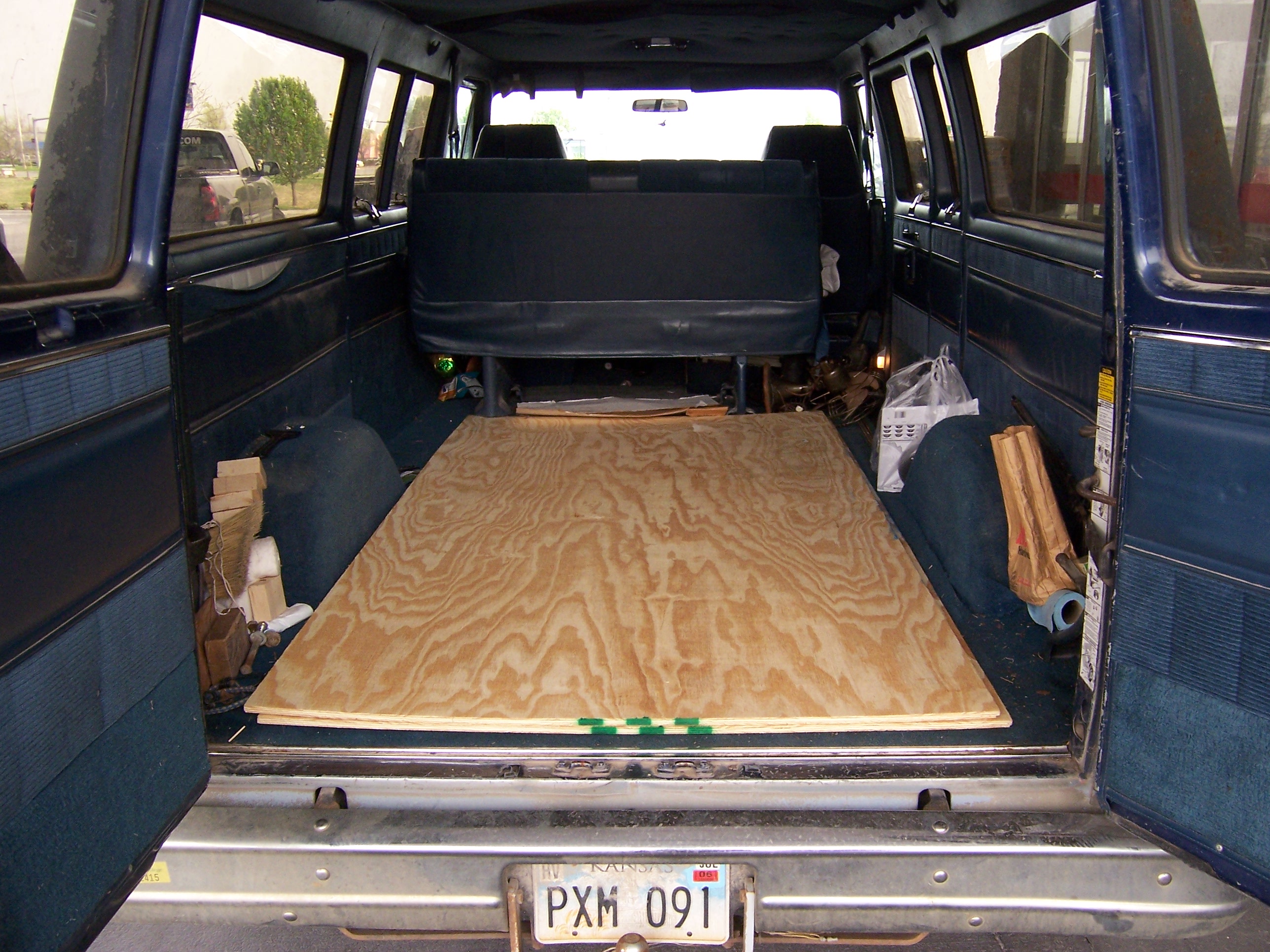
It all started a little over two weeks ago, at Lowe’s with two sheets of 15/32″ plywood in the back of the Possum Van. The cabinet is about the size of an arcade game, and they’re normally made from ~3/4″ plywood; but this won’t have to stand up to the same kind of abuse they take, so I figured ~1/2″ would be fine. It also reduces the weight dramatically, making it less difficult to lug around.

Plywood in the Back of the Van

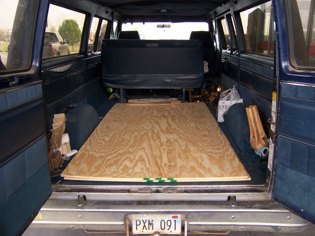
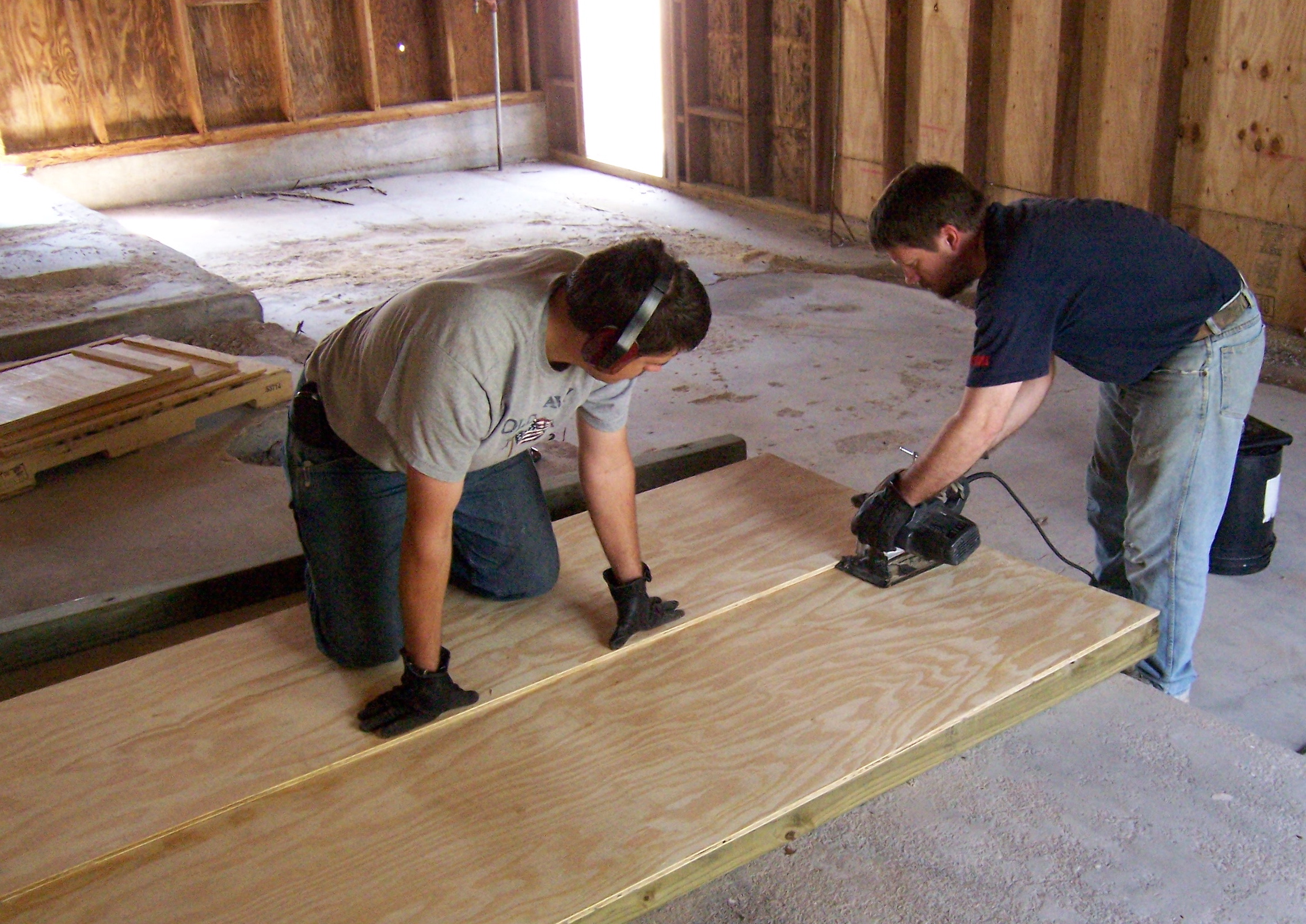
A friend and his son helped with some of the initial cuts. Because my tablesaw isn’t very accessible, and I don’t have an extension table anyway, we were cutting plywood on the floor (on 4×4 supports) using my circular saw, and the factory edge of another plywood sheet as a guide. I picked up a new Freud blade for under $15, and it’s incredible–very sharp, very easy to push, very clean cuts. We were all amazed. No more $7 Piranha blades for me!

Ripping Plywood

Starting the Base

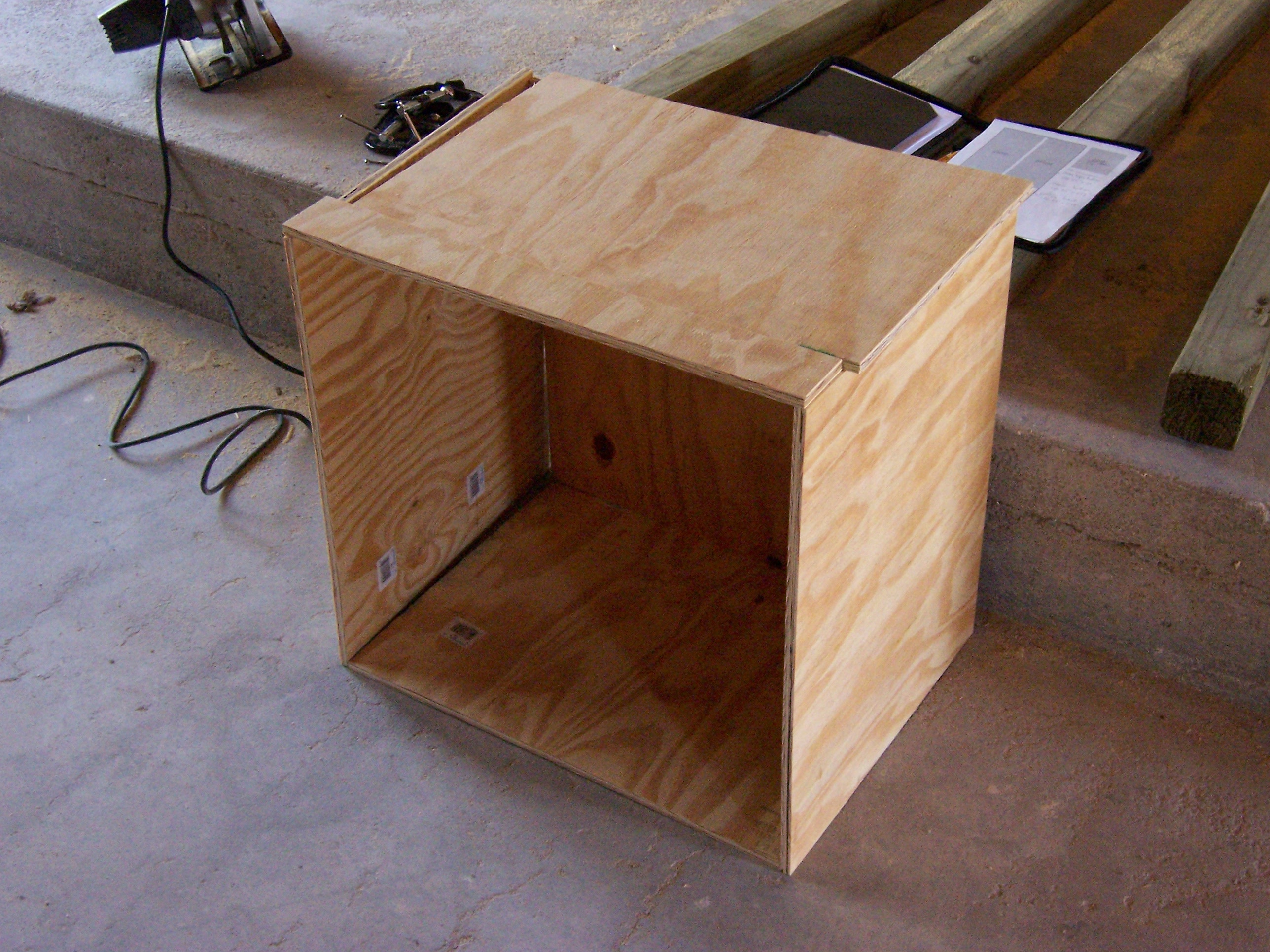
For load-bearing elements (the top and bottom of the base cabinet, the bottom of the upper cabinet, and the inner back of the upper cabinet), I used 3/4″ plywood that I had on hand. After cutting all the pieces for the base, I leaned them together to make sure they were sized correctly to fit the way I intended.

Cabinet Base Leaned Together

Not shown here is assembly of the cabinet pieces. I used my biscuit joiner for the whole thing. The biscuit joiner is basically an angle grinder with a very small (3″) circular saw blade and a fancy fence. You hold it up against the edge of a board, squeeze the trigger, and push it against the wood; it cuts a little slot in the wood. You repeat that on the opposing edge that you want to join; then take “biscuits,” little pieces of compressed beechwood that look like flattened footballs, jam them into the slots with glue, and have a pretty solid joint with (theoretically) perfect alignment. Since I was working alone most of the time, it would have been difficult to shoot a picture of the biscuiting process.

Building the Picture Frames

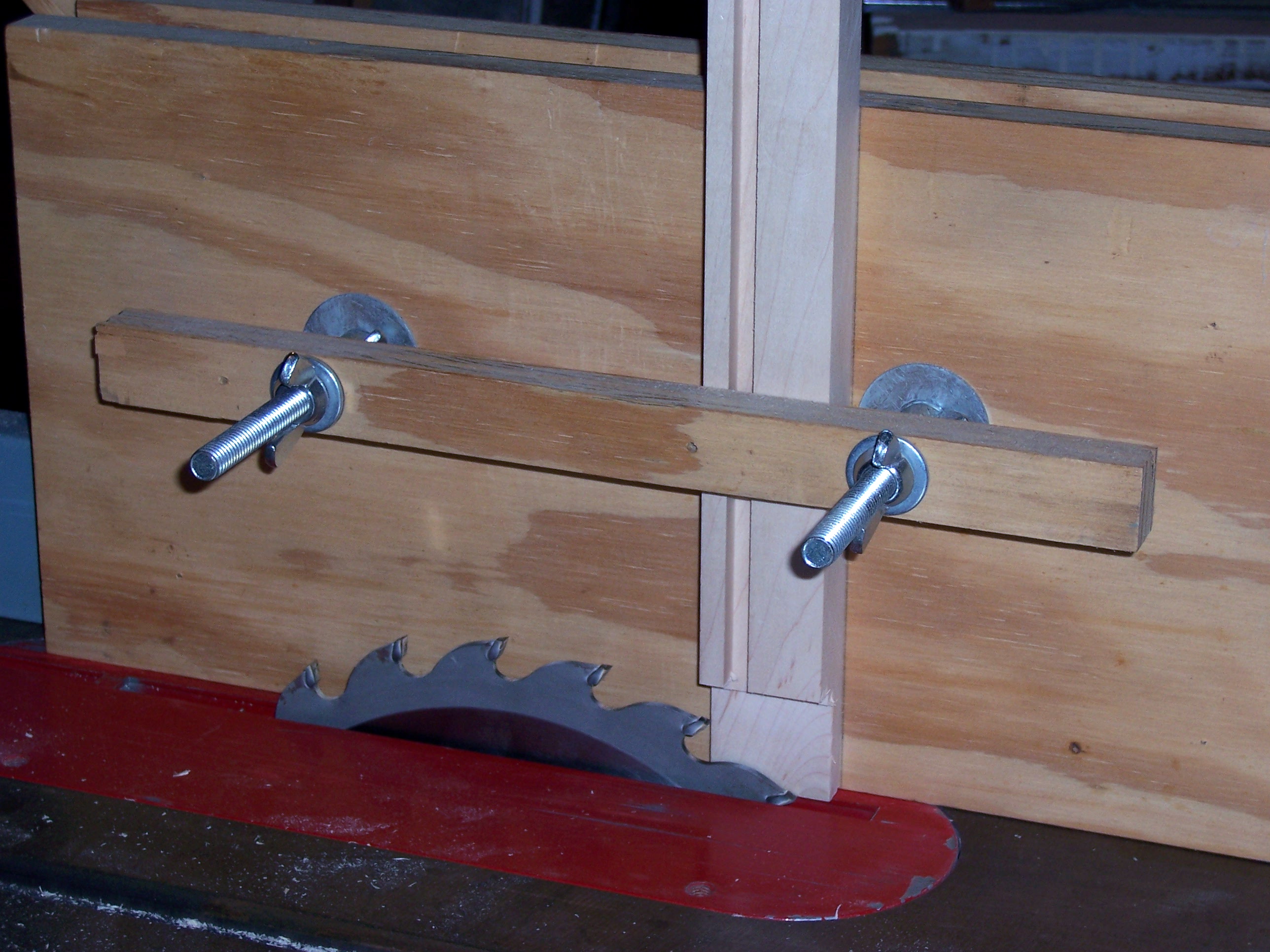
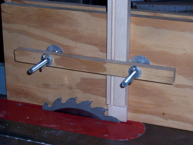
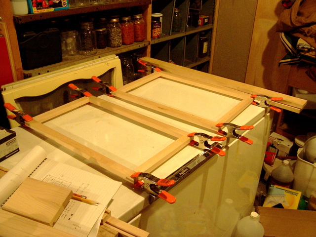
The front of the cabinet will have three swinging “picture frames,” which I made from maple that I had lying around. I used through mortise and tenon joints on the corners for strength, and cut them on a friend’s tablesaw using his tenoning jig.

Tenoning Jig

The joints fit pretty snugly, so they didn’t take much clamping during glue-up. (Love the random white-balance shifts my camera makes on indoor shots!)

Gluing up Picture Frames

Back to the Shop for the Rest of the Cabinet

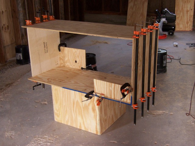
Because the cabinet’s side panels are continuous from top to bottom (they’re on the outside, not interrupted by any horizontal elements), they had to be glued on last, so I had all the other parts of the base assembled before adding the sides. I wasn’t sure yet how smoothly the glue-up was going to go, so I did them one at a time. In order to seat the biscuits as well as possible, I ended up locating a clamp over each one. You can never have too many clamps.

Gluing up Cabinet Base

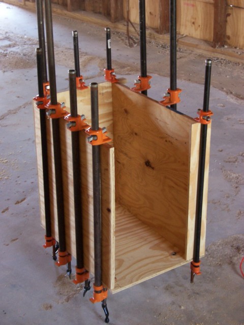
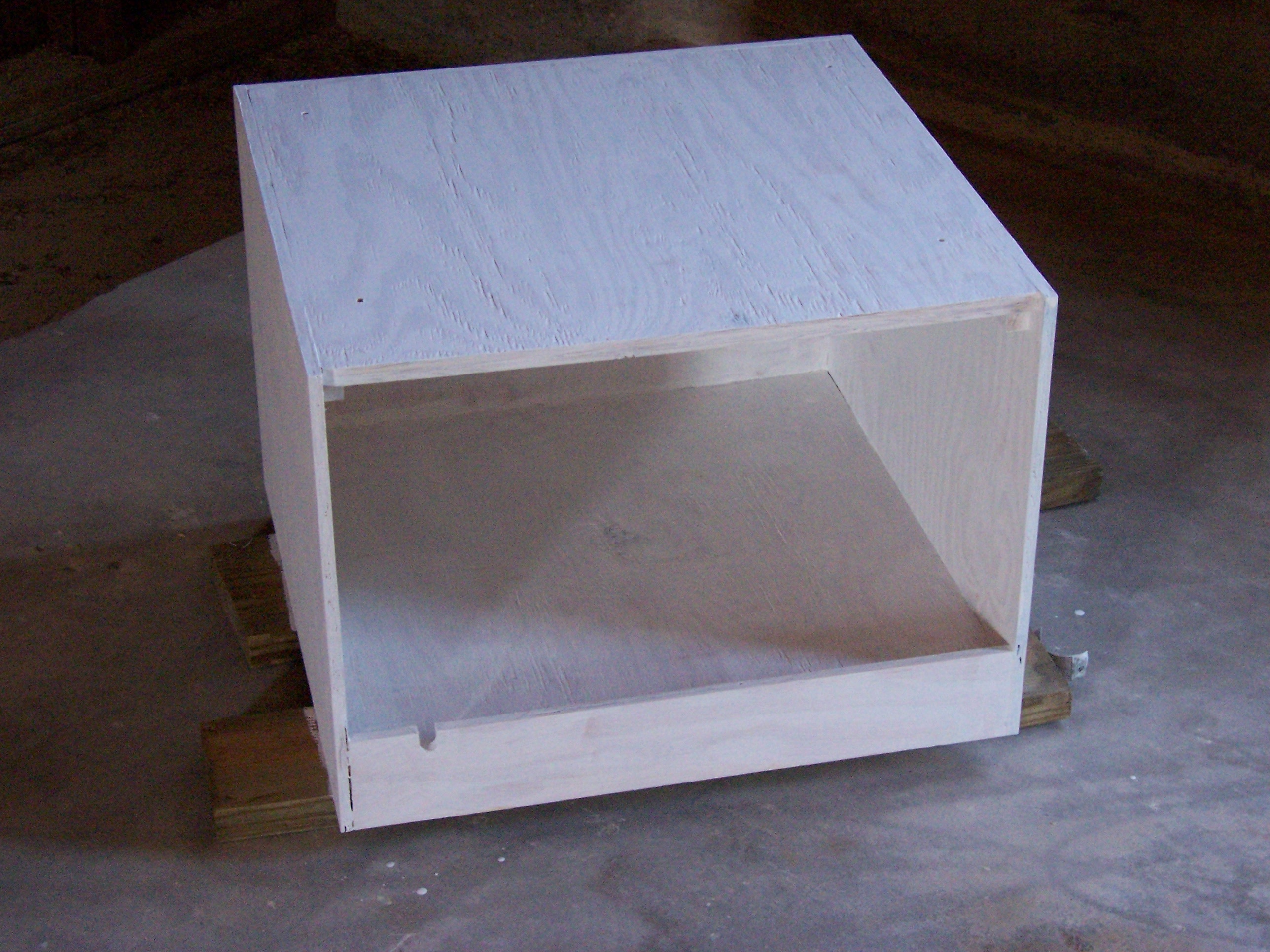
After completing the base, I glued up the outer frame of the upper cabinet. (It’s sitting on the assembled base.) Due to the design of the interior, I knew I was going to have to add the coffin panels last–and this meant that the outer frame would be unsupported whilst gluing it up. I clamped on a couple of pieces of scrap plywood to hold it square during assembly until dry. Once again, one pipe clamp over each biscuit.

Gluing Upper Cabinet Exterior

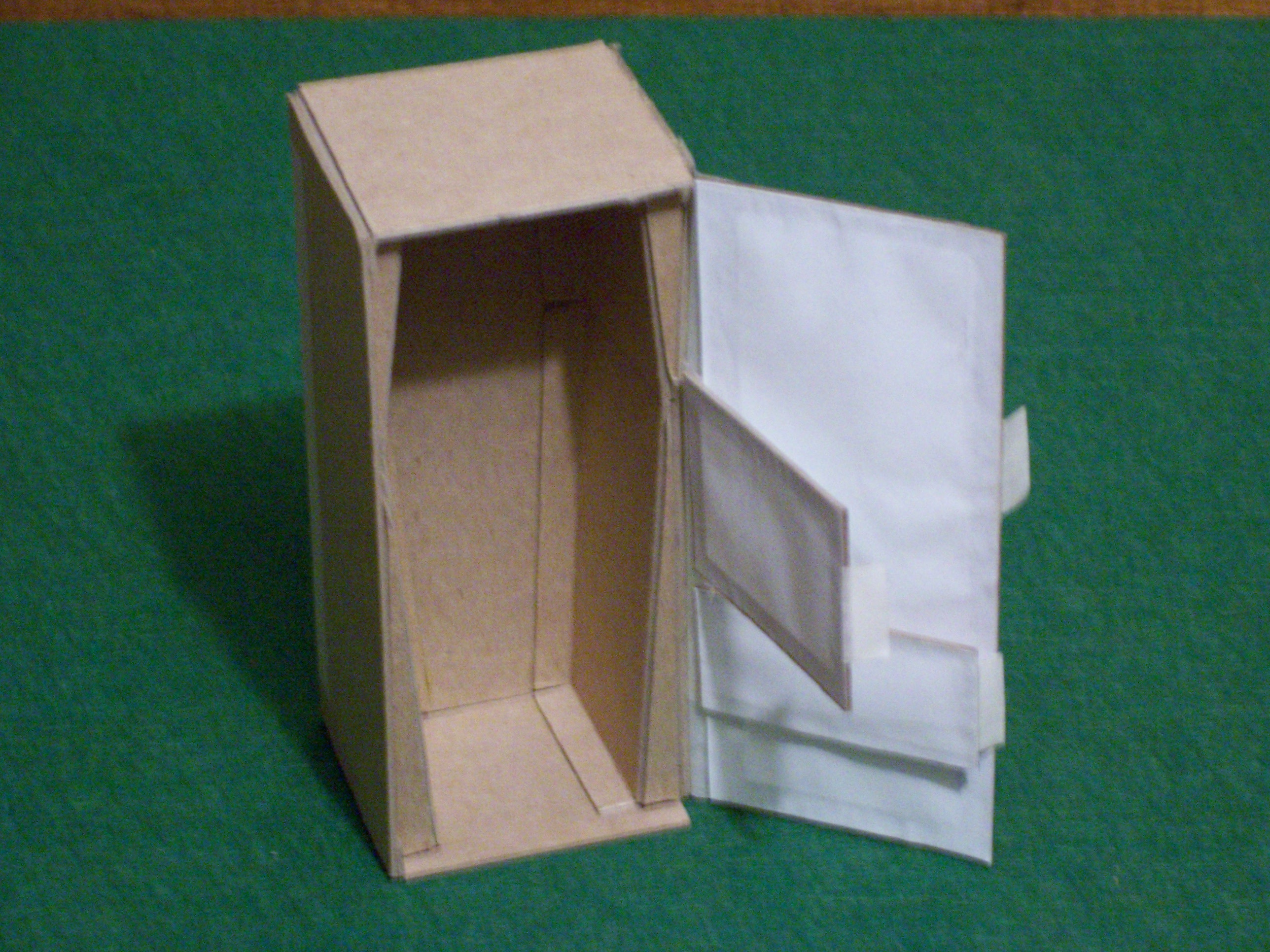
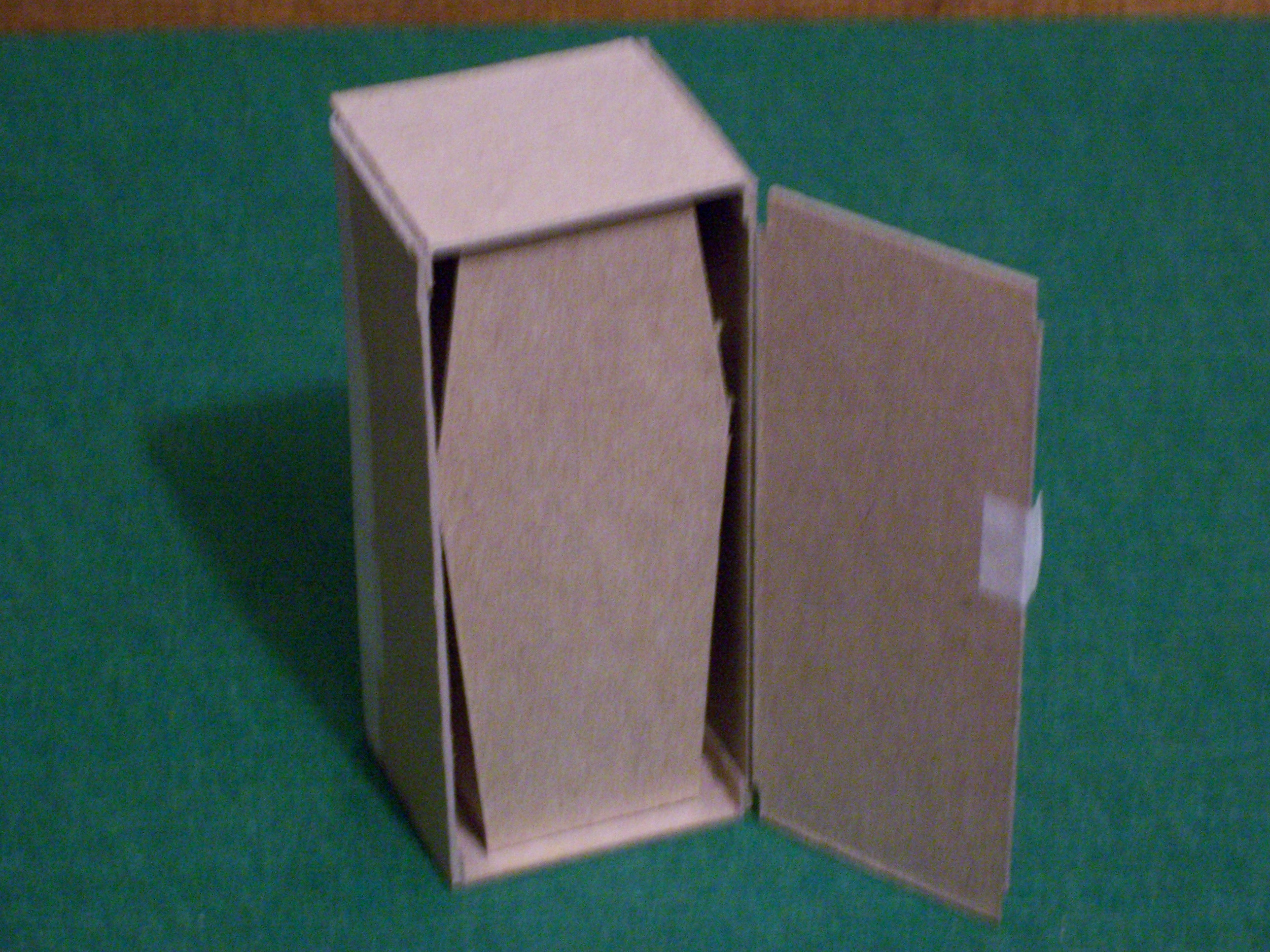
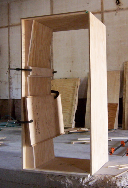
Because the upper cabinet is so large, I was really concerned about the integrity of its corners when I turned the outer frame upright–but I had nothing to worry about; it turned out to be surprisingly sturdy. I test-fit the panels for the coffin liner, then cut the liner fronts from more maple stock, using my tapering jig on a tablesaw. I left them a bit long so I could fit them exactly once I got them back to the cabinet–then regretted having done so, when I didn’t have a good way to cut them to size back at the shop.

I biscuited the fronts onto the liners and let them dry, then fitted the entire assembly into the outer shell and biscuited the outer liner ends to the shell ends, the fronts to the shell edges, and the inner liner ends into the shell sides. I needed gravity’s help during assembly, so I built one liner at a time with the cabinet laying on edge, then turned it upright to clamp and dry. I used scrap stock to hold the inner liner ends tightly against the cabinet shell across their entire width.

Gluing Left Coffin Liner

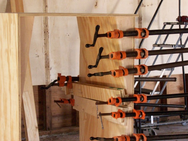
The biscuit joints on the right liner ended up a little more snug than those on the left, so I used a clamp per biscuit to pull them together. I would have used C-clamps for the entire face-to-shell joint, but I only have four 4″ clamps, so they’re all on the bottom section. The weight of all the pipe clamps sticking out the right side made the cabinet almost a little tipsy.

Gluing Right Coffin Liner

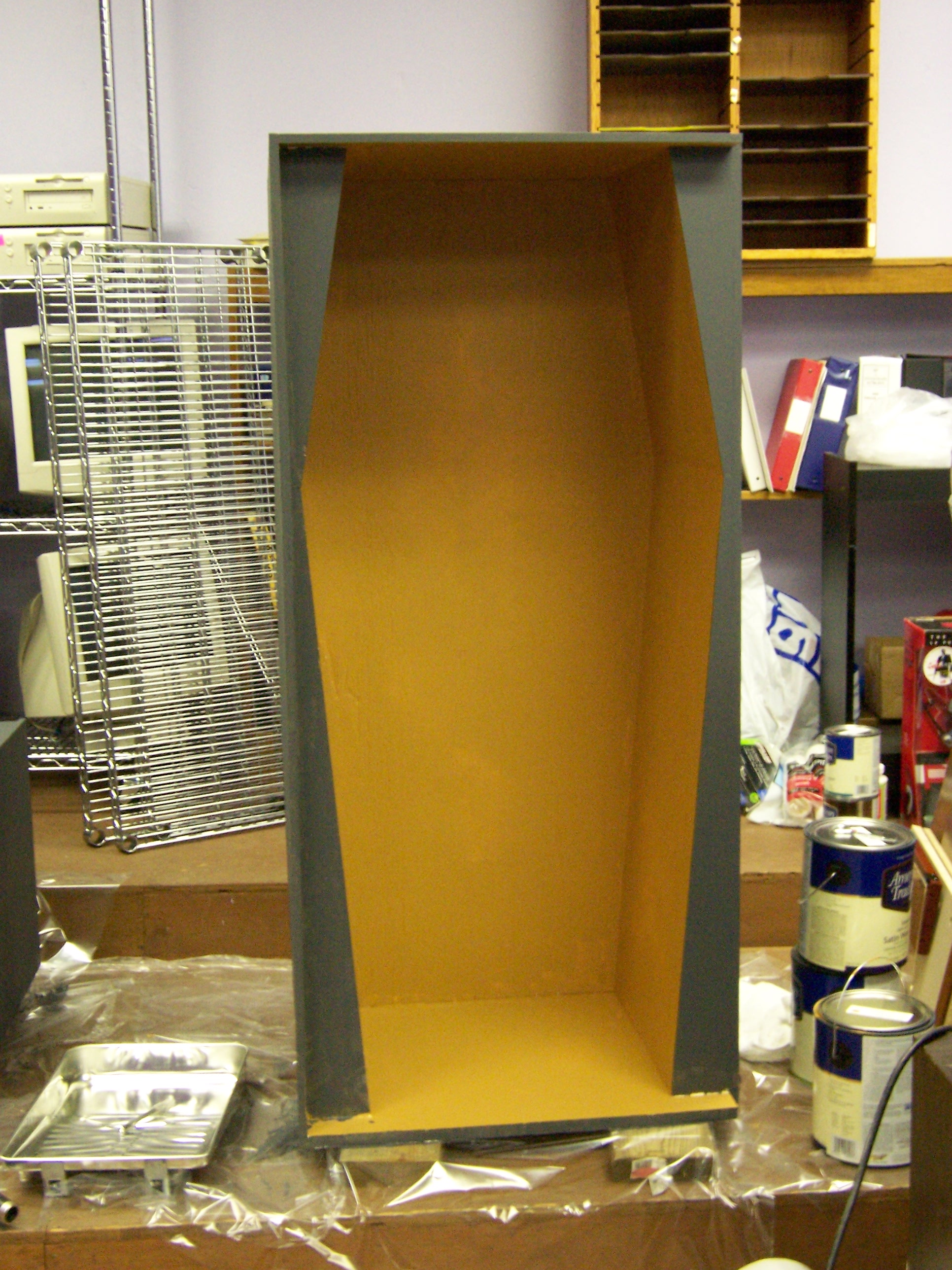
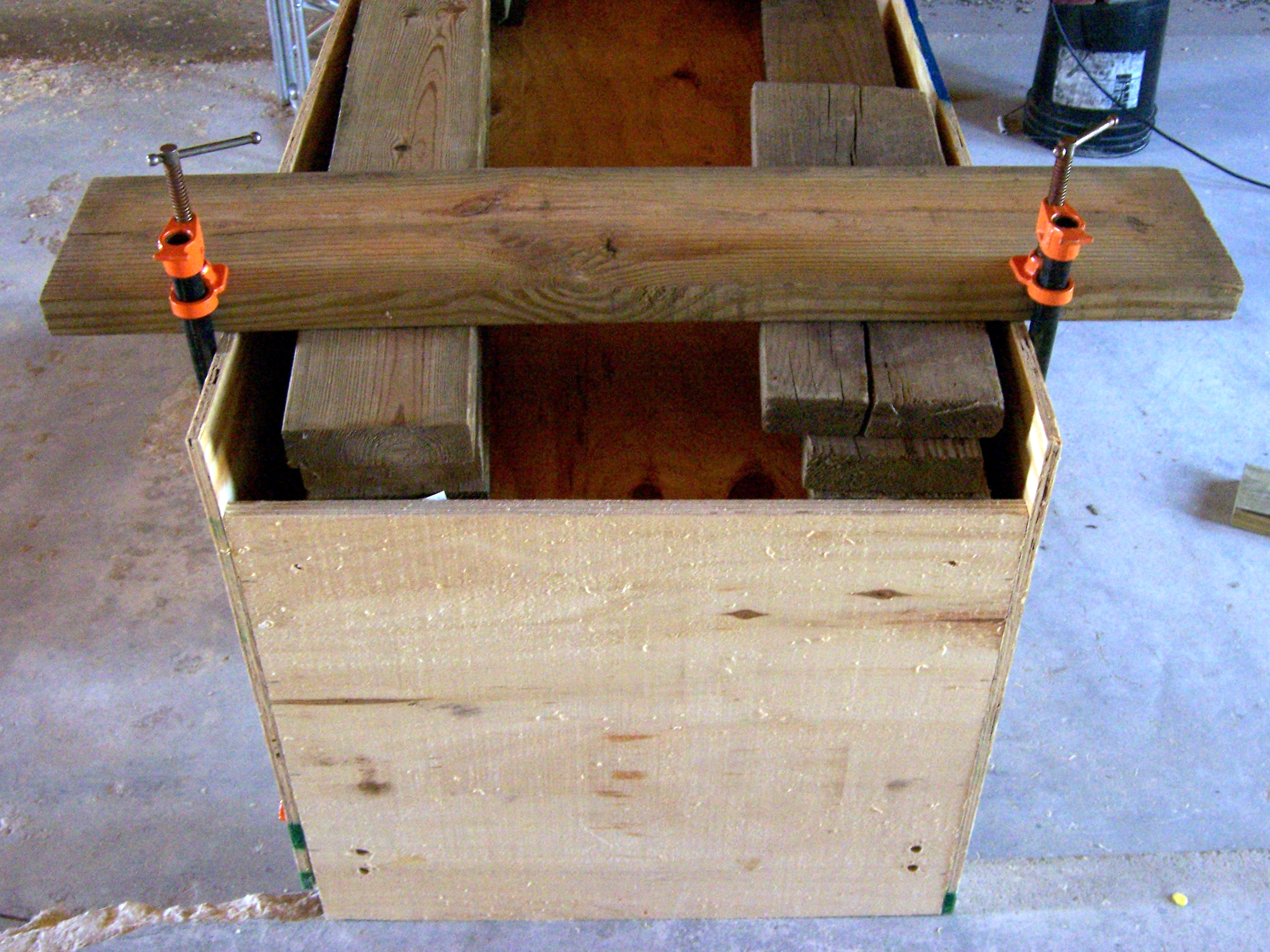
It’s not easy to see from this shot, but the coffin back is recessed a few inches into the cabinet, leaving a “service area” between the false back and the actual back door. That made it tricky to clamp the coffin back onto the coffin edges. I laid the whole cabinet upside down across a concrete ledge and a bucket (suspended to leave room on the bottom to attach clamps), stacked scrap 2x6es above the biscuits, laid a longer 2×6 across each end, and clamped that down tightly to the cabinet.

Gluing Coffin Back

I’m particular enough that I know I would have clamped it tightly like that anyway. However, in this case it was actually necessary–the coffin back was bowed about an inch and a half from end to end, so the top popped completely clear of its biscuits while clamping the bottom. Some of the biscuit joints were pretty loose, so I was really nervous it was going to spring open when I removed the clamps–but it held very nicely (thank goodness). If we do have any problems with it, I can always put some nails in from the back.

Finishing Touches

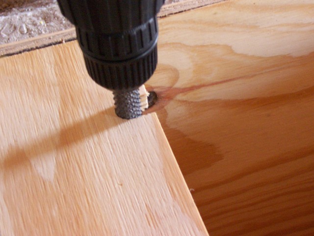
I needed a notch in the back of the base, for the power cord to come out when the back door is closed:

Base Notched for Power Cord

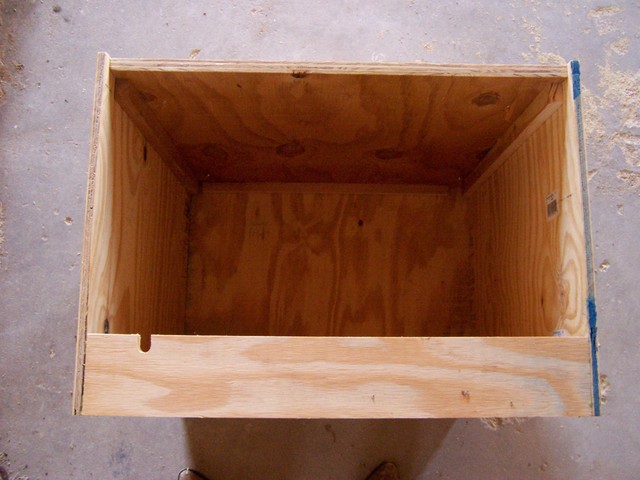
While the coffin back was drying (I gave it a long time, to be safe), I borrowed a rotary rasp and ground out the notch for the cord.
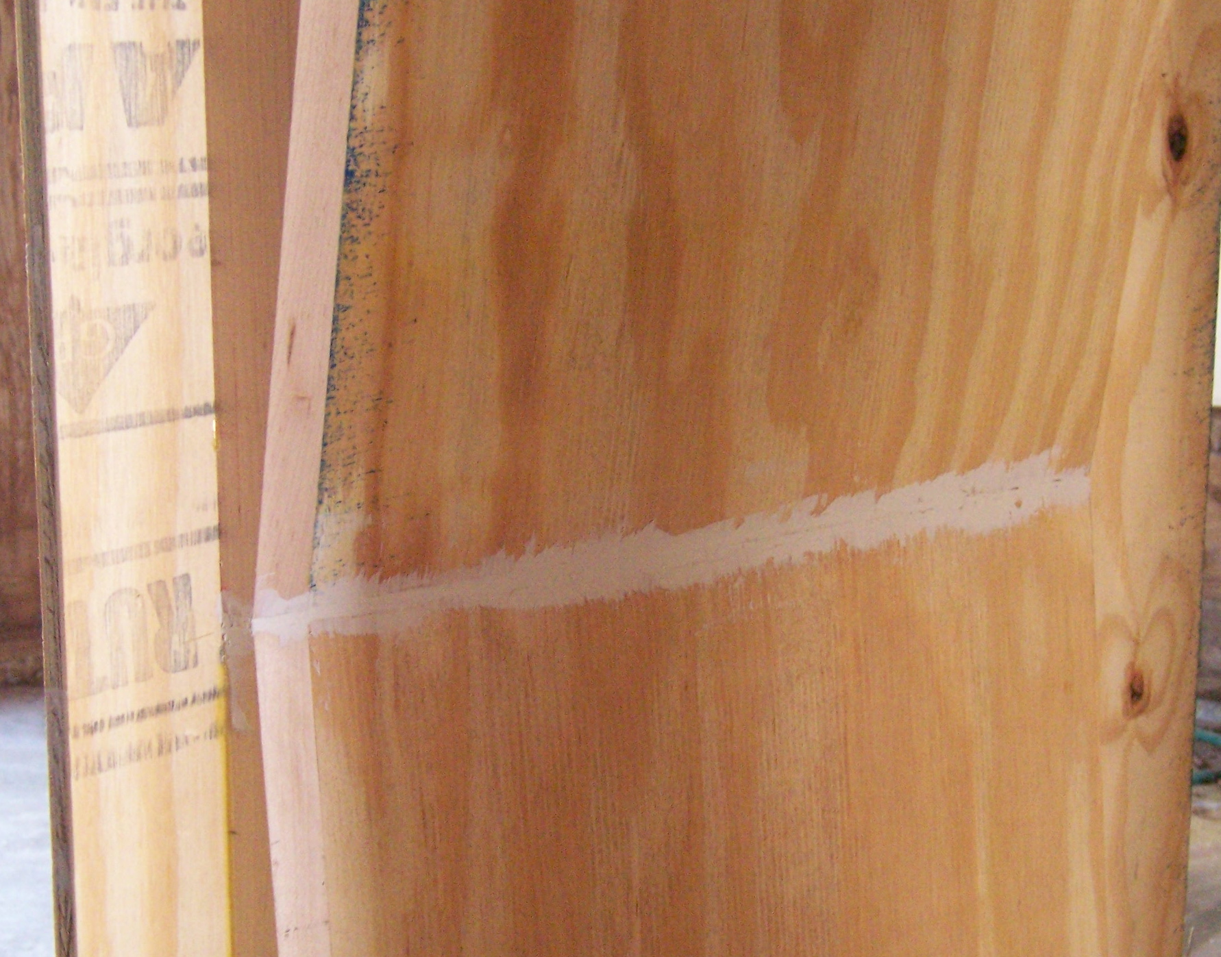
Notching Base with Rotary Rasp

Putty

My cuts and joints weren’t perfect, and I had some cracks to fill. (They would have been better had I been able to use a tablesaw for the large pieces, but still not perfect.) I gooped them up pretty nicely with some painter’s putty and a putty knife, then did some final sanding to smooth up the plywood before priming.
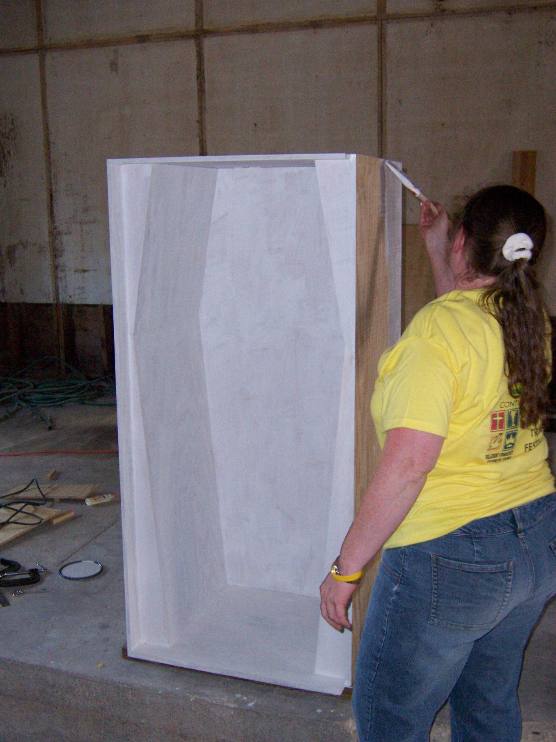
Puttying Cracks

Primer

Because plywood just drinks up paint, I put two coats of oil-based primer on all of the visible (exterior) surfaces, and a single coat on all of the interior (back-side) surfaces to help seal against humidity changes. The primer said it dries to topcoat in only eight hours, and I was very impressed with how dry it was by this morning. I haven’t uploaded those pictures yet–they’ll come in the next post.

Cabinet Modeling

Tuesday, April 4th, 2006

Andrea and I envision the cabinet for our TechArt final project, A Woman’s Mind, being built in two sections, for ease of hauling it around. The large, upper portion will contain the visible elements of the exhibit; and the small, lower portion will house the computer, UPS, LogoChip, cooling fans, etc.

Tonight, I modeled the upper portion of the cabinet, to get a better feel for the proportions, and to have something more concrete to use when discussing construction details with Andrea. I used an amazing new CAD package called CardBoard (TM). Its user interface is incredibly intuitive; and in addition to the basics like Cut and Paste, it offers operations I’ve never seen in other CAD software, such as Slice, Fold, and Tape.

As you can see below, it has stunningly photorealistic, three-dimensional renderings, even going so far as to simulate shutter shake and mismatched white balance across multiple views.

Here’s the upper portion of our cabinet with all of the screens closed. Note that the picture-frame of the outer screen is excessively wide; I hadn’t yet figured out how to model it at a narrower setting.

Cardboard Cabinet Model, Front View

The outermost panel obscures the entire contents; opening it reveals smaller screens, and begins to expose the shape of the cabinet interior. Again, the picture-frame is a bit wide and not necessarily to scale.

Cardboard Cabinet Model, Front Panel Open

Opening all of the front panels reveals the entire shape of the cabinet interior; as well as the head (monitor), heart, and fertility mechanisms (not yet modeled).

Cardboard Cabinet Model, All Panels Open

The rear panel will be locked and will open only for maintenance, providing access to a shallow false back and to the space surrounding the false interior. These spaces will hold the wiring needed to connect the sensors and actuators to the LogoChip, as well as the cables from the computer to the head monitor.

Cardboard Cabinet Model, Back Open

I plan to model the lower portion tomorrow night, working from the outline drawing of my earlier post. Hopefully Andrea and I can talk it over in class Thursday, and I can start actual construction this weekend.

Cabinet Plans: First Draft

Monday, April 3rd, 2006

First Draft of Cabinet Design

Multiplexing Ultrasonic Sensors

Monday, April 3rd, 2006

Last week in class, we talked about the potential need to have multiple Devantech SRF-05 ultrasonic sensors connected to one LogoChip. Different LogoChip output pins could connect to the different sensors’ trigger inputs, and then the sensors’ echo signals could all feed into one LogoChip input (because only one would be triggered at a time). We were trying to draw how to connect them together without burning them up, and I knew there was a right way to do it but couldn’t think of diodes.

Here it is:

Schematic to Multiplex Ultrasonic Sensors to One Digital Input

The echo signals are TTL, active high. That means that when the signal comes back, the sensor’s output will change from 0V to 5V. Put another way, 0V is normal; 5V means an echo was detected.

The diodes are one-way “valves” that allow electricity to flow from a sensor to the LogoChip when the sensor’s output is high (echo detected), but not from one sensor to another, under any circumstances. This protects the sensors from shorting each other out. When all of the sensors’ outputs are low, no electricity flows through the diodes to the LogoChip, so the pulldown resistor connects the LogoChip’s pin to ground (weakly) for a default input of low.

You could use some of Tom’s multiplexing techniques to connect even more ultrasonic sensors, but at $25 each, I expect cost will be the issue before running out of LogoChip pins.