Last night, I prototyped the transmitter circuit; today, I worked on the receiver. Coe’s design uses a two-stage op-amp circuit, with AC coupling on the input from the transducer to the first stage, to amplify the received signal before sending it to a comparator. I wanted to do the same, but I prefer to run from a single supply voltage, so I used an LM324 and added voltage dividers to bias the signal up to 2.5V.
First, I powered up the circuit from last night and measured the receiver’s signal on my scope. With the transmitter and receiver about 2” apart, the receiver signal was about 2V peak-to-peak, attenuating to about .5V p-p at 2’. If it continues to attenuate by a factor of 10 every 2’, then to measure distance out to 10’ (round trip of 20’), the received signal would be 2 * 10-10, or .2nV. Let’s hope that’s not the case!
The Circuit
Each stage of the amplifier circuit is taken directly from the LM324 datasheet, “AC Coupled Inverting Amplifier” (although the two stages are DC coupled). The receiver’s signal is AC-coupled to the first amplifier’s inverting input, with a 2.5V bias to the non-inverting input.
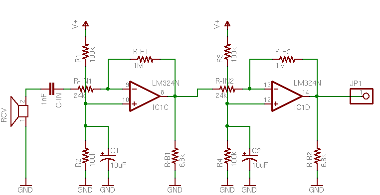
I’m not sure why C1 is needed on the bias voltage divider, but the output waveform was considerably cleaner with it than without, so I left it in. I also don’t know what RB does, and Forrest Mims’ Engineer’s Mini Notebook on op-amp circuits didn’t show it but the datasheet did, so I left it in as well.
Values
The bandwidth-gain product for the LM324 is 1MHz, so a 24kHz input means the maximum possible gain is about 41.7. The gain is set by the quotient of the feedback and input resistors, and it worked very naturally to select RF = 1MΩ and RIN = 24kΩ.
According to Mims, CIN should have a value of 1 / (2π flow RIN), where flow is the lowest frequency to pass the filter. This gives CIN = 1 / (2π 24kHz 24kΩ) ≅ 280pF–except the first time around, I mistakenly calculated using RF (1MΩ) instead of RIN (24kΩ), and got 6.6pF. I had a 10pF on hand, so I substituted it; but it was still far too low a value, as will be seen shortly.
I breadboarded the circuit on my workbench and measured about .04V peak-to-peak directly from the receiver element, with both transducers pointed at the ceiling. (That was about an 8’ round trip, so my dire prediction of .2nV was fortunately not the case.) Next, I measured only about .08V p-p at the output of the first amplifier stage, so obviously something was wrong. It was at this point that I added C1, which brought the amplifier output to about .1V and cleaned it up dramatically–but with a gain of 40, it should have been more like 1.6V.
I was suspicious about the value of the AC coupling capacitor, CIN, and began substituting different values for it, with the following results:
| Condition | Signal Amplitude |
|---|---|
| direct transducer output | .04V |
| CIN = 10pF, C1 absent | .08V |
| CIN = 10pF, C1 = 10uF | .1V |
| CIN = 100pF | .5V |
| CIN = 1nF | .6V |
| CIN = 10nF | .6V |
It looked like I must have miscalculated by an order of magnitude (at this point, I hadn’t yet caught my frequency error in the calculation), and 100pF was probably close to the best valued, but still a little too far down the knee of the filter’s response curve. .6V output was still a little low for a gain of 40, but within a range I was willing to accept, given that I was estimating the values by counting hashmarks touched by a dirty, wiggling waveform on my scope. I put the 1nF back in and called it good.
Second Stage
After honing the values on the first stage of amplification, the second stage was easy–just more of the same. I used all the same values, but omitted the AC coupling capacitor, since I’m happy to DC-amplify around the 2.5V bias. The second stage gives me a trapezoidal waveform (clipping both the top and bottom of the transducer’s sine wave) running rail-to-rail of the LM324′s advertised output capacity–from 0V to about 4V. Tomorrow I need to run that through a comparator to clean it up just a little more, and then steal John’s capture/compare LogoChip code to start timing the echoes.
please send the first part i.e.TRANSMITTER of this project
thanx
Zubair, it’s the previous post.
The voltage divider made by R1 and R2 allow power supply noise onto your noninverting input. C1 and C2 form a low-pass filter that can eliminate some of this noise. That is probably why you noticed a cleaner signal with them installed.
On the other hand, I have no idea what RB is, either.
This is a nice circuit.
I have a recommendation:
Two comparators have the same reference voltage already.
Remove R3,R4 and C2 from the schematic.
And, then, connect Pin 12 to Pin 10.
Save space and components on the circuit
Omer, you’re absolutely right — since the reference voltage goes to a high-impedance op-amp input, the same voltage divider can be used for both stages. Good catch!