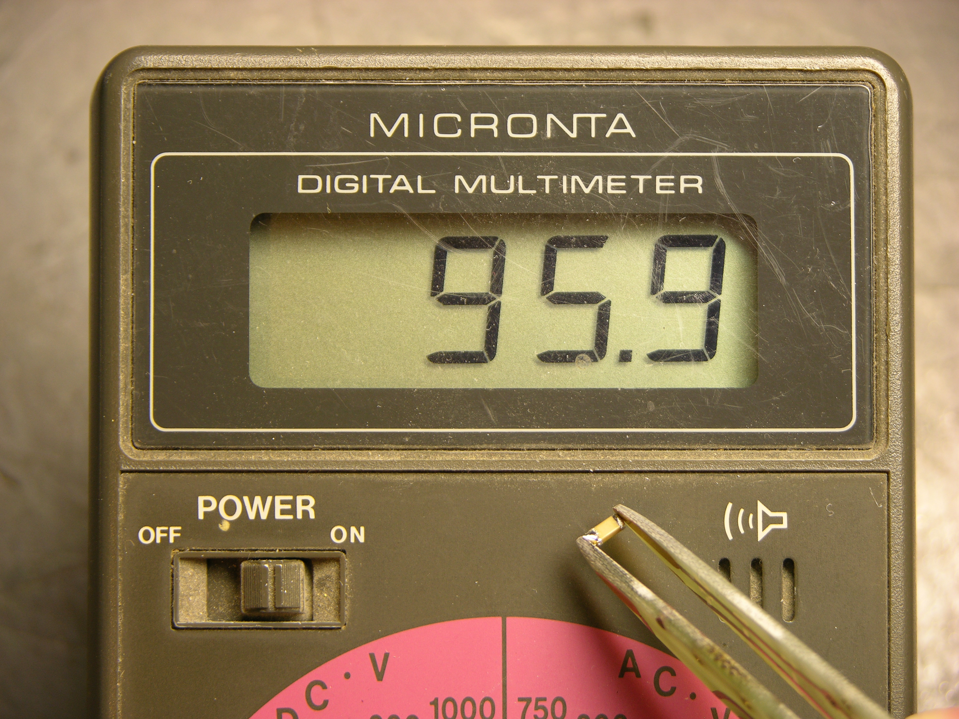
Some surface-mount resistors have their values printed on them, but all 1206 and smaller SMT capacitors that I’ve seen are completely blank. The only way to determine their value — after salvaging, that is — is to measure them.
My multimeter has a capacitor tester, but its connections are slots in the body of the meter rather than the regular probes, so it doesn’t work at all for SMT capacitors. (In fact, most salvaged capacitors’ leads are much to short to make contact with the meter’s sockets.) Lately I’ve been plugging a couple of long wires with tinned ends into the meter so I can use the other ends to check the values of SMT capacitors on my workbench.
This is a pain.
Ever since I started salvaging SMT components, I thought it’d be great to have a pair of tweezers wired as meter probes — grab the component, pick it up to put away, and check its value all at the same time. There actually are such things available, but the ones I’ve found start at $35 with a custom connector for that manufacturer’s meter. Not much to my liking.
I figured on building my own, maybe by finding a pair of plastic tweezers and gluing some kind of metal foil to the gripping surface. But what kind of metal? I was thinking about this on the drive to work Monday. Copper oxides rapidly and wouldn’t make good contact in the long term; so does solder. Silver would probably be okay. Gold would be perfect, but I have no idea where to get . . . wait a minute. Sure I do.
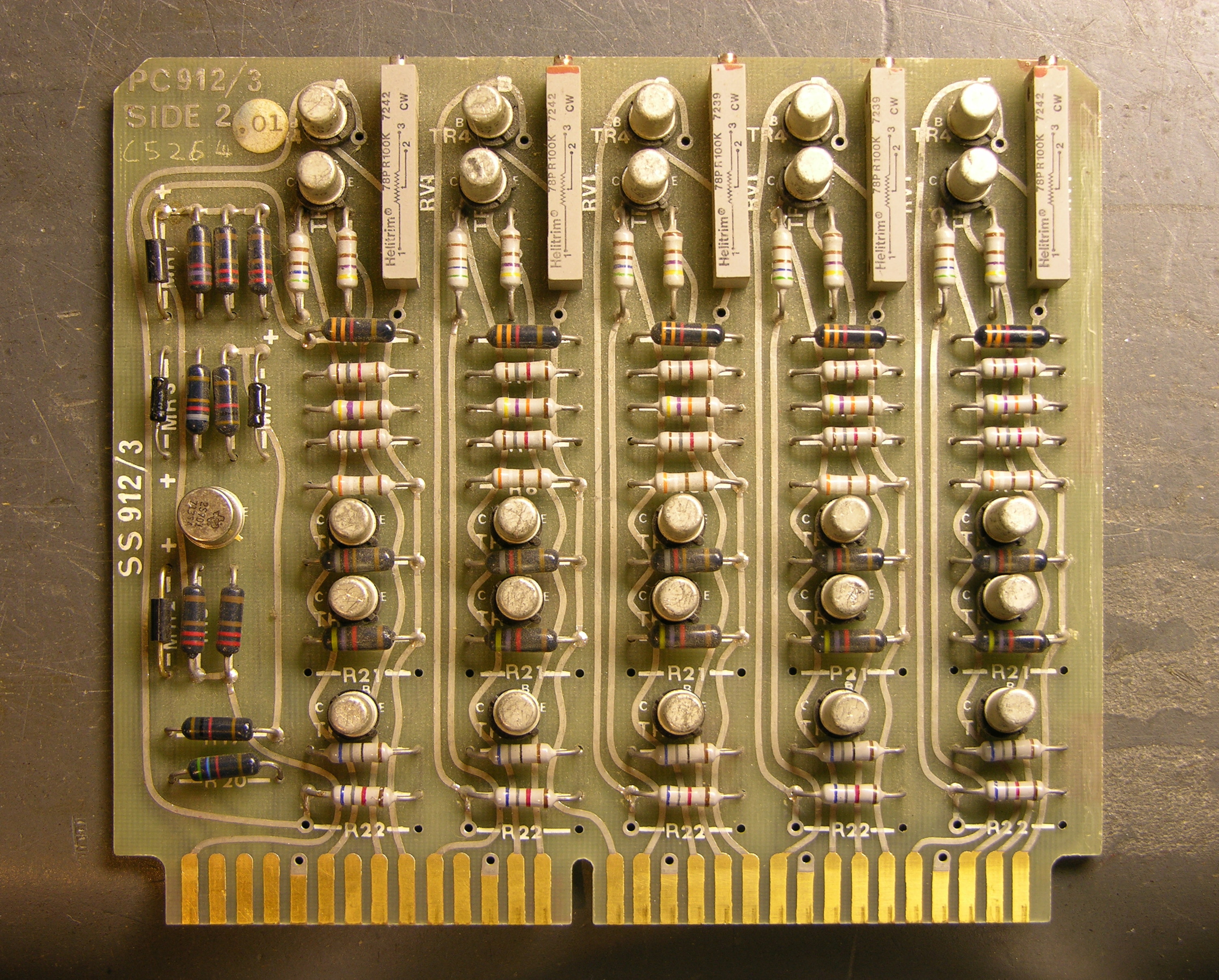
Monday night I sifted through my junk boxes and found a sacrificial circuit board with a nice, wide, gold-plated .156″-spacing card-edge connector on it. I desoldered everything from it the hard way — with a soldering iron — because this time it was about preserving the board rather than removing components as fast as possible.
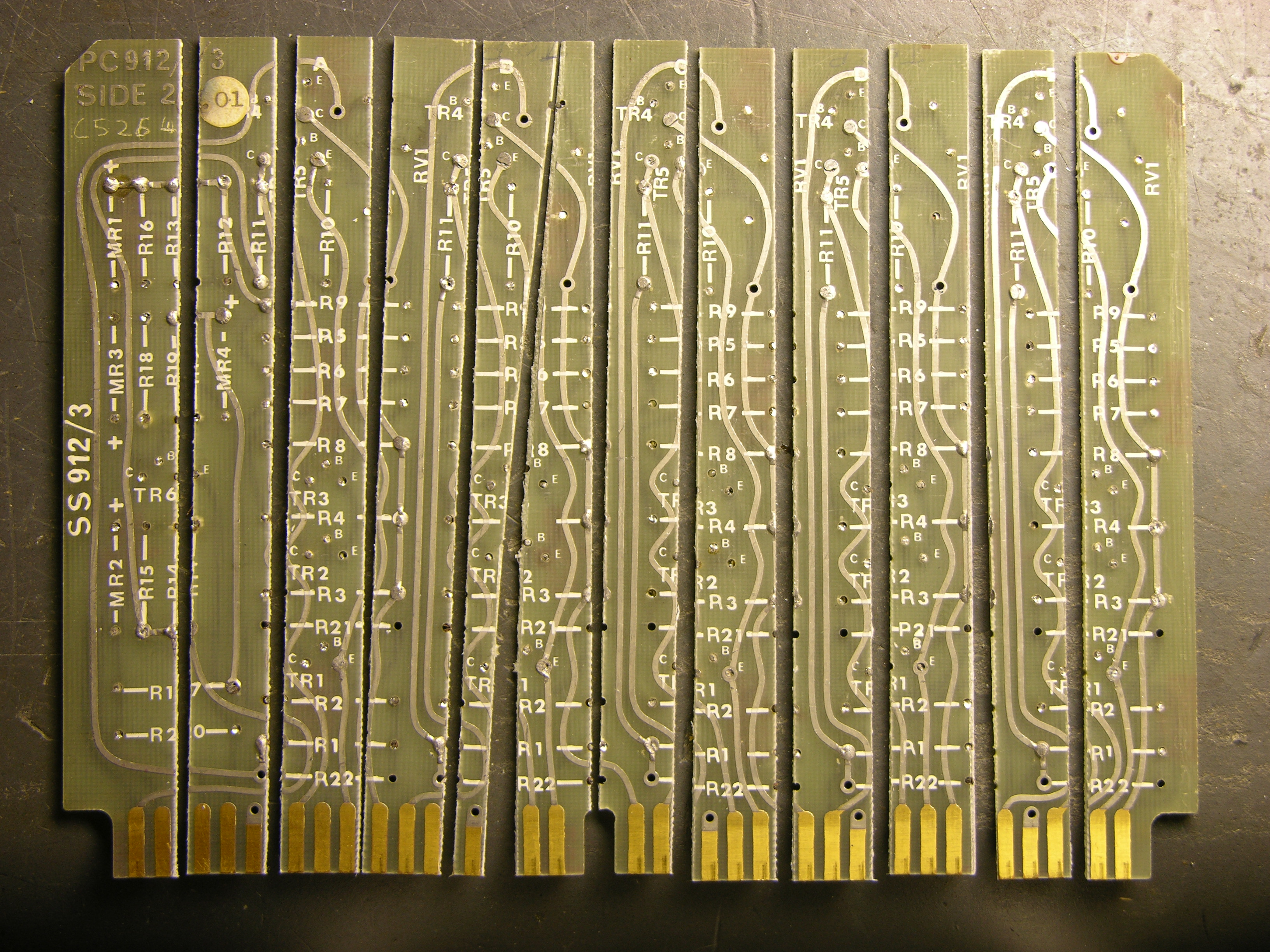
Tuesday I took the stripped board to the lab at school and used the PCB shear to cut it into strips, many of which are almost straight. That night I cut a pointed shape onto the end of two strips on my scrollsaw, doing a terrible job. I did slightly better on the next ones.
I used the bench disc sander to smooth them out and narrow the points to the width of the gold strips, then bevel the edges near the tips so the edges are sharp like a knife instead of thick like a PCB edge — it makes it easier to pick up very not tall SMT components. I also sanded the tip’s angle back from 90° to about 60°, since I’ll be holding these at an angle from my hand down to the workbench.
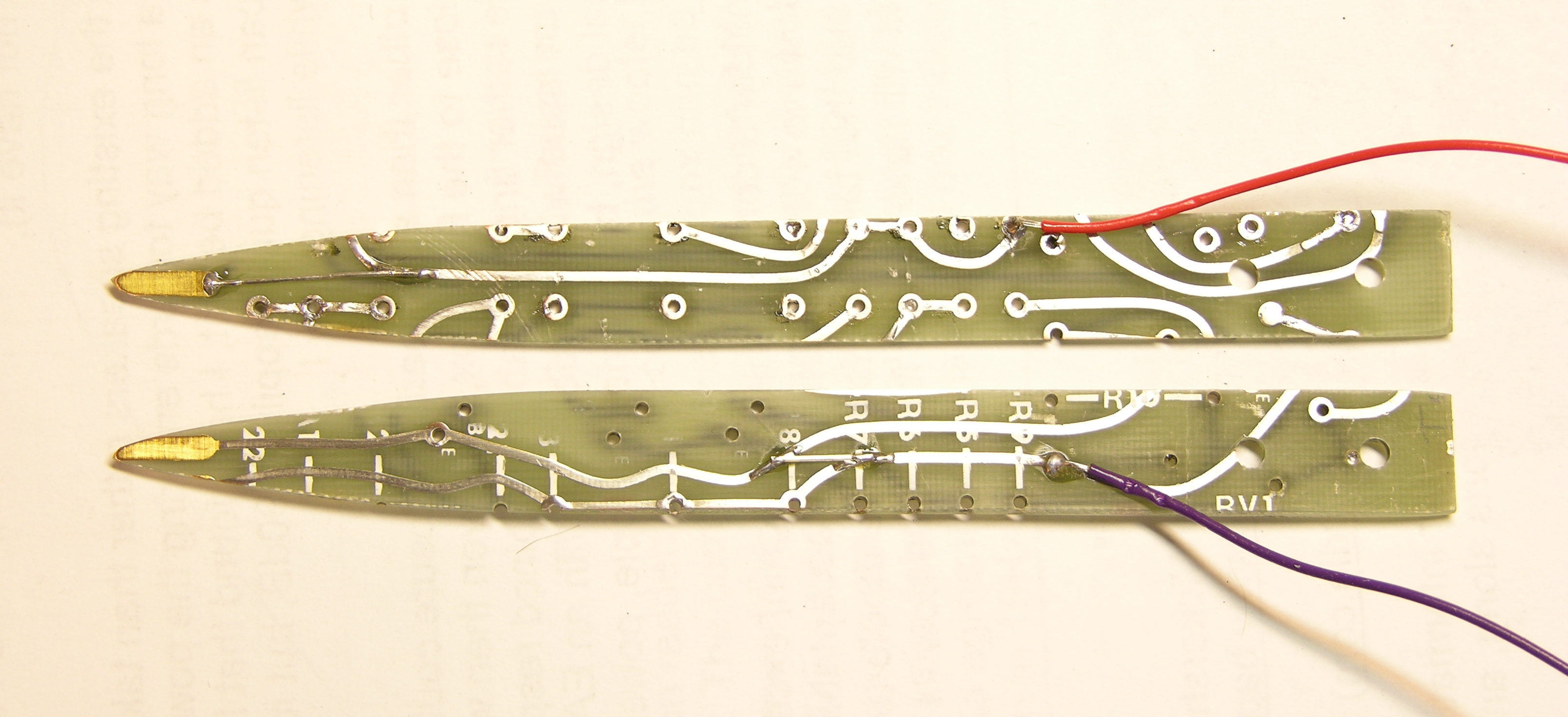
This afternoon I wet-sanded them very smooth, both faces and edges, then soldered a couple of jumper wires so I could use the existing traces to get from tip to handle, and soldered on two lead wires.
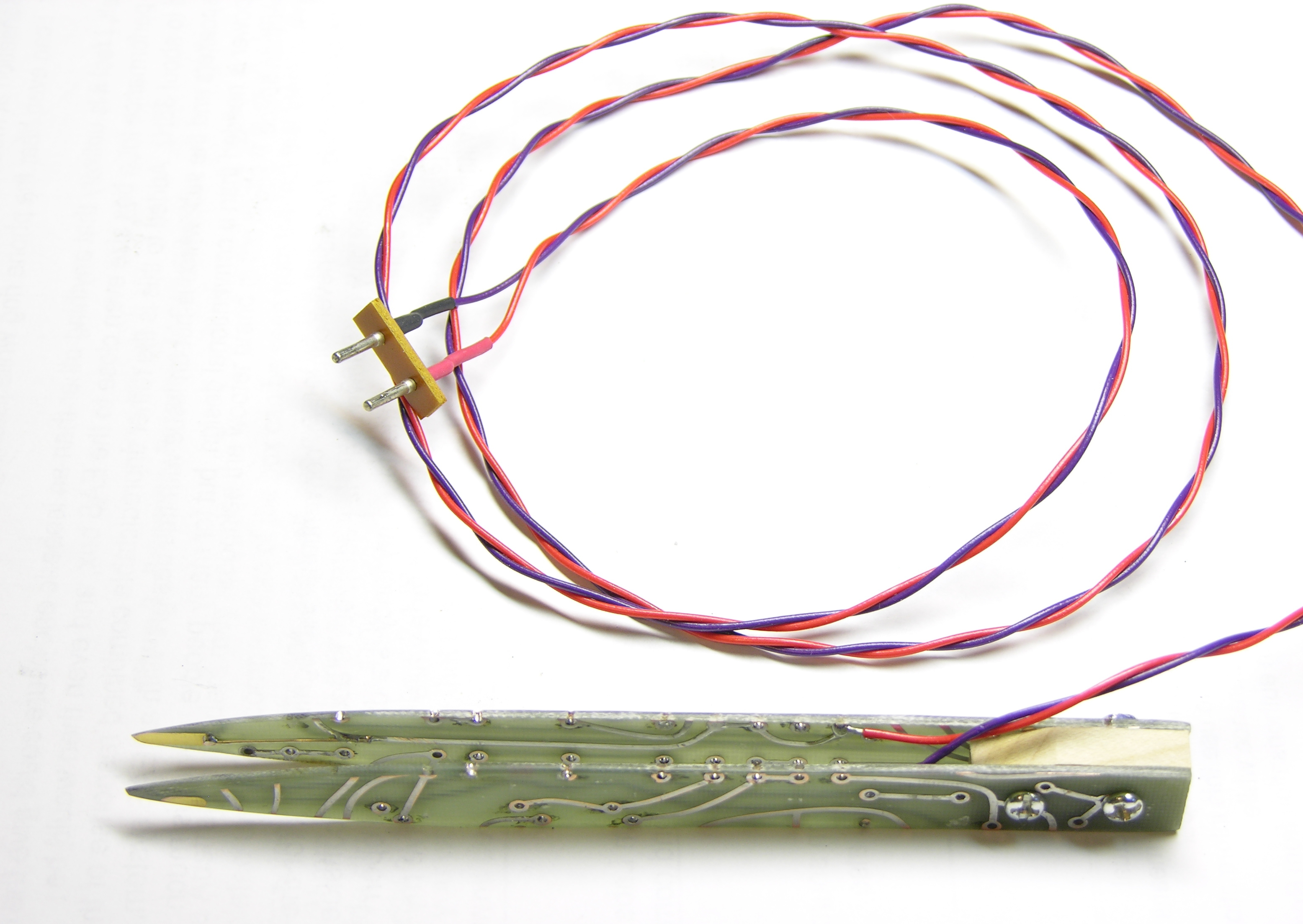
I taped the points together in alignment, clamped the handle end in a vise with a maple chunk in between, drilled holes through the works, and bolted it together. I had to cut one trace to keep it from contacting the bolts — it wouldn’t have shorted the two leads together, but I still didn’t want the bolts “live” on either side of the connection.
At the far end, I soldered to a salvaged plug (something from a CRT monitor yoke PCB, I think) to fit into the capacitor test slots on my meter.
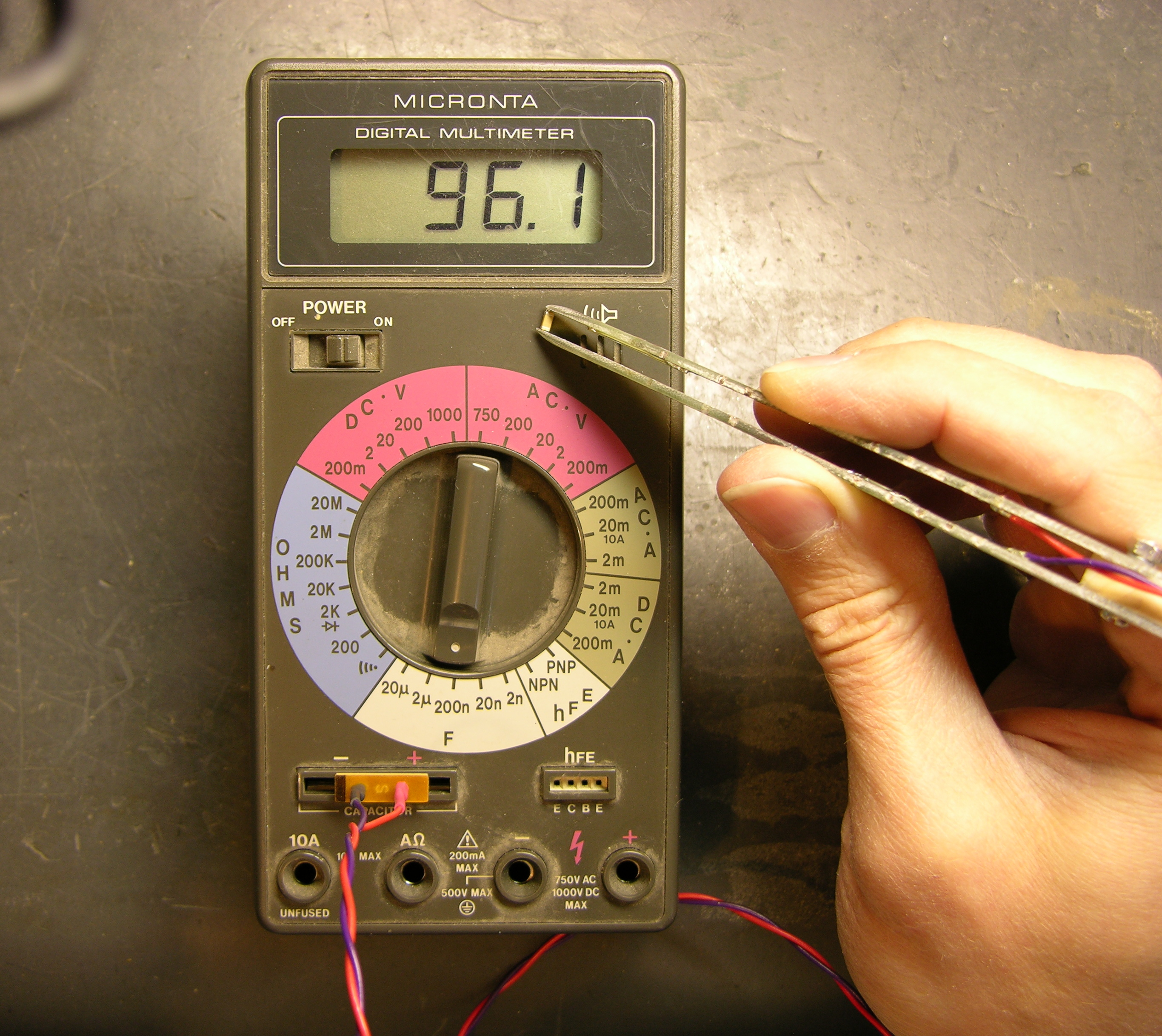
It works very nicely. The tweezer adds about 50pF to my measurements when it’s wide open, 60pF when I hold it as closed as I can without shorting; so probably 50pF when I’m holding a capacitor in it. That’s only a .05% error on the .1μF SMT capacitors I have in abundance, and I bet my meter itself is two orders of magnitude less accurate than that, so it really doesn’t bother me.
I think I have the jack that mates with the plug, and I want to build an adaptor to banana plugs so I can use this to double-check SMT resistor values, too.
Now I’m out of excuses not to put away all the SMT chips sitting out on my workbench. ![]()
Great idea
May be it would be useful to add some electronics to compensate the 50 pF offset.
Greetings from Spain
Very nice problem solving. I need to build one of these to check out a ton of SMT parts I have scrounged. I usualy skip the caps becase they are too much trouble but even so I still have a bunch.
It might be better to cut the traces off closer to the Gold fingers and solder the wires down there, rather than soldering the wires where you have. The issue is that your fingers will contribute to the capacitance somewhat, and, depending upon how your grip varies, they may shift the measured value slightly. Note that PC board material has a relatively high dielectric constant. And, if the traces being used have via holes to traces where
your fingers connect, then all sorts of screwy readings may result.
If I were going to do it, I’d probably etch off all of the traces more than about a half inch from the Gold fingers, leaving smooth, unplated board for the finger holds.
Oh, of course, I tend to deal with much smaller capacitor values usually, so maybe I’m hypersensitized to this (few dozen pF, rather than .1 uFs)
Anyway, it’s a neat idea.
Dave
I did it by taking actual cheap tweezers, sawing out two gold contact fingers from a thick old pcb, and filing the back side of the small pcb pieces into a wedge shape – so they could be cyano-glued into the tips of the tweezers thick end first and soldered to with enough clearance. Add some heatshrink (never. ever. be without some) around the solder joints and tweezer handles, and presto….
you get a blunt front, of course, but the wedges also add some grip on the part….
Nice re-use of materials. I have plenty of PCI cards around so I think I will be making one of these as well.
Alexander, you might want to look for an ISA (or even older) card — the wider the card-edge traces, the easier it is to make the tweezer tips.
Sorry to repeat myself – PCI card edges are much too valuable since they have a 1/20″ raster – so do many SO packages. Perfect mounts.
Keith – great idea. I am just starting to scrounge SMT components, and will need to measure them. This “tip” will help greatly! J.
Great idea! I love these hands on hacks. I saw another hack on a product I bought the other week. I tried it out and it works a treat! It enables my PSU to fine tune voltages with ease. The link to it is: http://www.rapidonline.com/weblog.aspx?id=49
Excellent idea. Wish I’d thought of it.
Faustian – what did you mean by “PCI card edges are much too valuable since they have a 1/20″ raster – so do many SO packages. Perfect mounts.”? Sorry, but it sounds like on one hand you’re saying not to use them (because they’re *too valuable*?), and then to go ahead and use them because they’re perfect. I’m just not following.
J Holmes –
Faustian’s PCI card edge comment referred to his comment on an earlier post. Rather than cutting up PCI cards to make tweezers, he uses the 1/20″ edge connector for prototyping SMT packages with 1/20″ lead spacing. Because of that, he’d prefer to sacrifice something else to make tweezers.