A couple of years ago, I received this automotive USB-connector power adapter as a promotion at a conference. I use it to keep my iPod nano charged in the car, but I’ve noticed it doesn’t charge my Blackberry well. To be precise, it doesn’t charge my Blackberry. In fact, I’ve never been clear whether it even slows the rate of discharge, and sometimes it seems like it speeds it. The Blackberry shows the lightning bolt charging symbol (The charging symbol is a lightning bolt, srsly? Ben Franklin is personally charging my phone?) but nobody’s home.
Note that I don’t blame the vendor whose logo happens to be on it — I’m sure they didn’t manufacture it.

After driving two and a half hours a week ago starting with a half charge on my BlackBerry, plugging it in midway through the trip, and arriving to have the BlackBerry finally shut off its radio due to depleted charge; and due to being in the presence of Cort; I decided it was time to see why the adapter couldn’t provide enough charge for the BlackBerry.
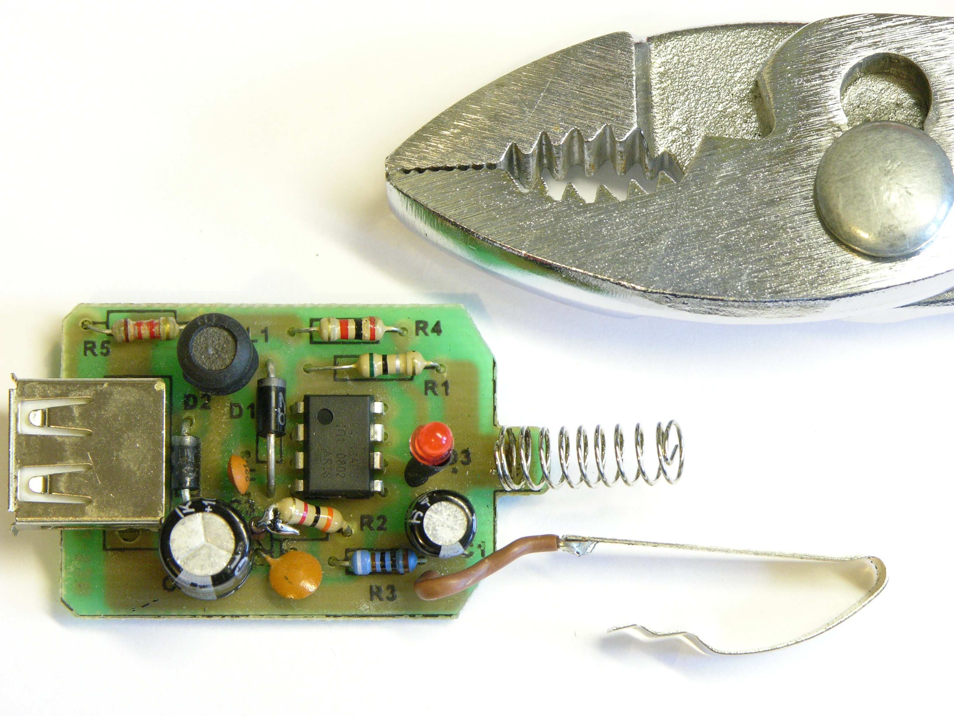
Inside the Power Adapter
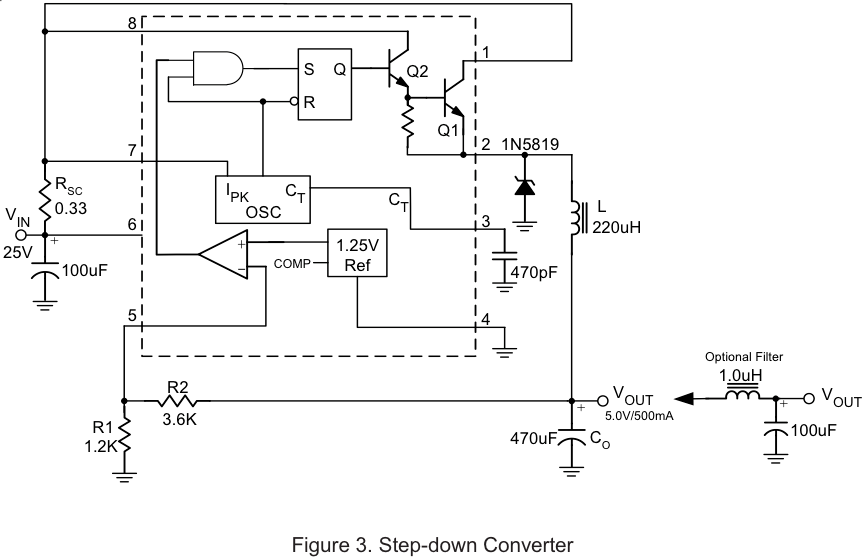
After peering and squinting at the control IC, I deciphered the part number RT34063APS and found a datasheet for the DC-DC converter. It contained no theory of operation but did provide one sample circuit for step-down conversion. The IC maintains 1.25V across R1, so R2 and R1 (on this diagram — different part numbers in the device at hand) program the output voltage by dividing VOUT. The values of 3.6KΩ and 1.1KΩ should program it for 5V operation.
RSC is supposed to program a current limit (SC is “sense current,” perhaps?), with the IC maintaining 330mV across VCC to VIPK. I’m not clear on how that limits the current, but I’ll take their word for it.
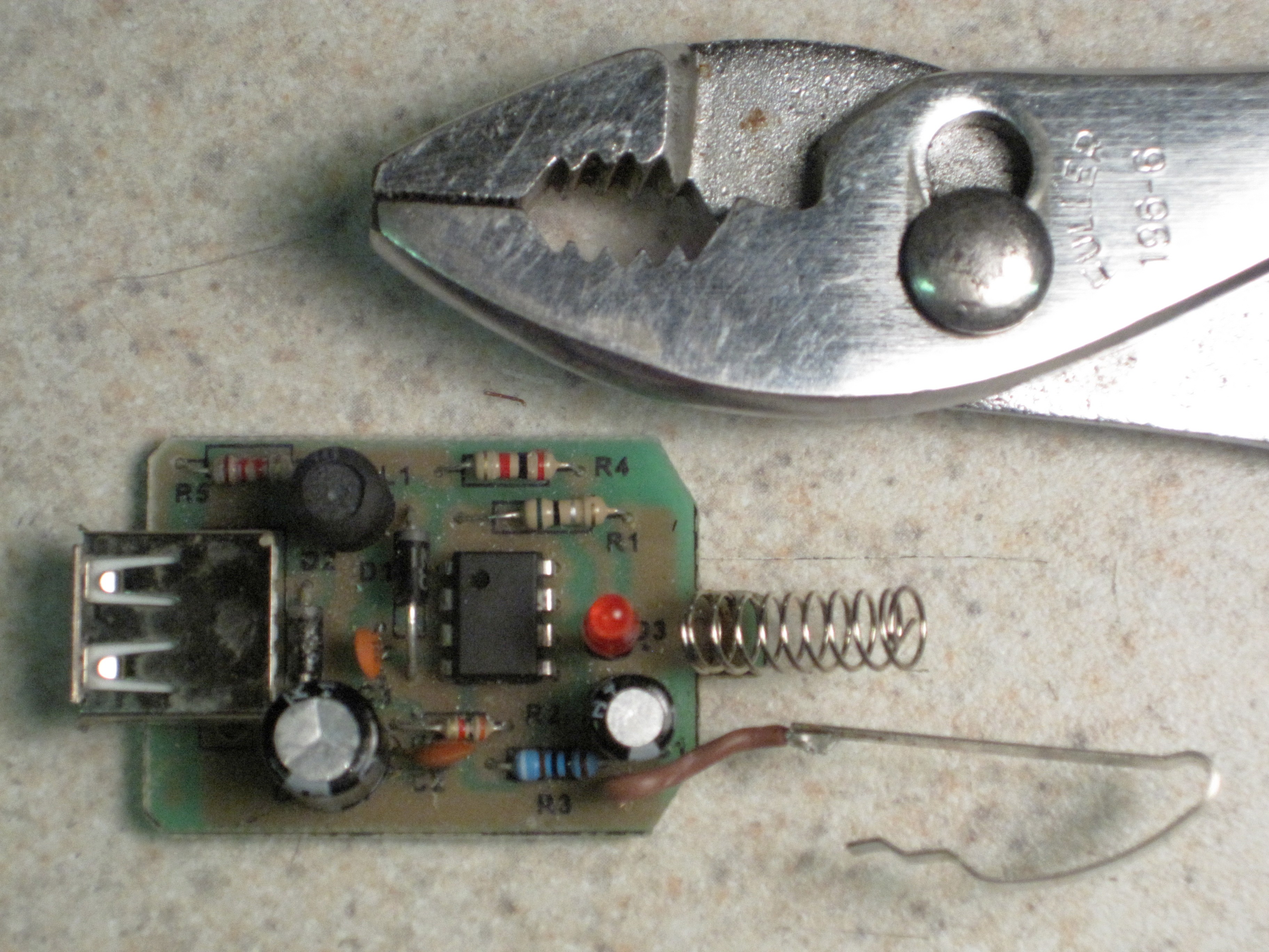
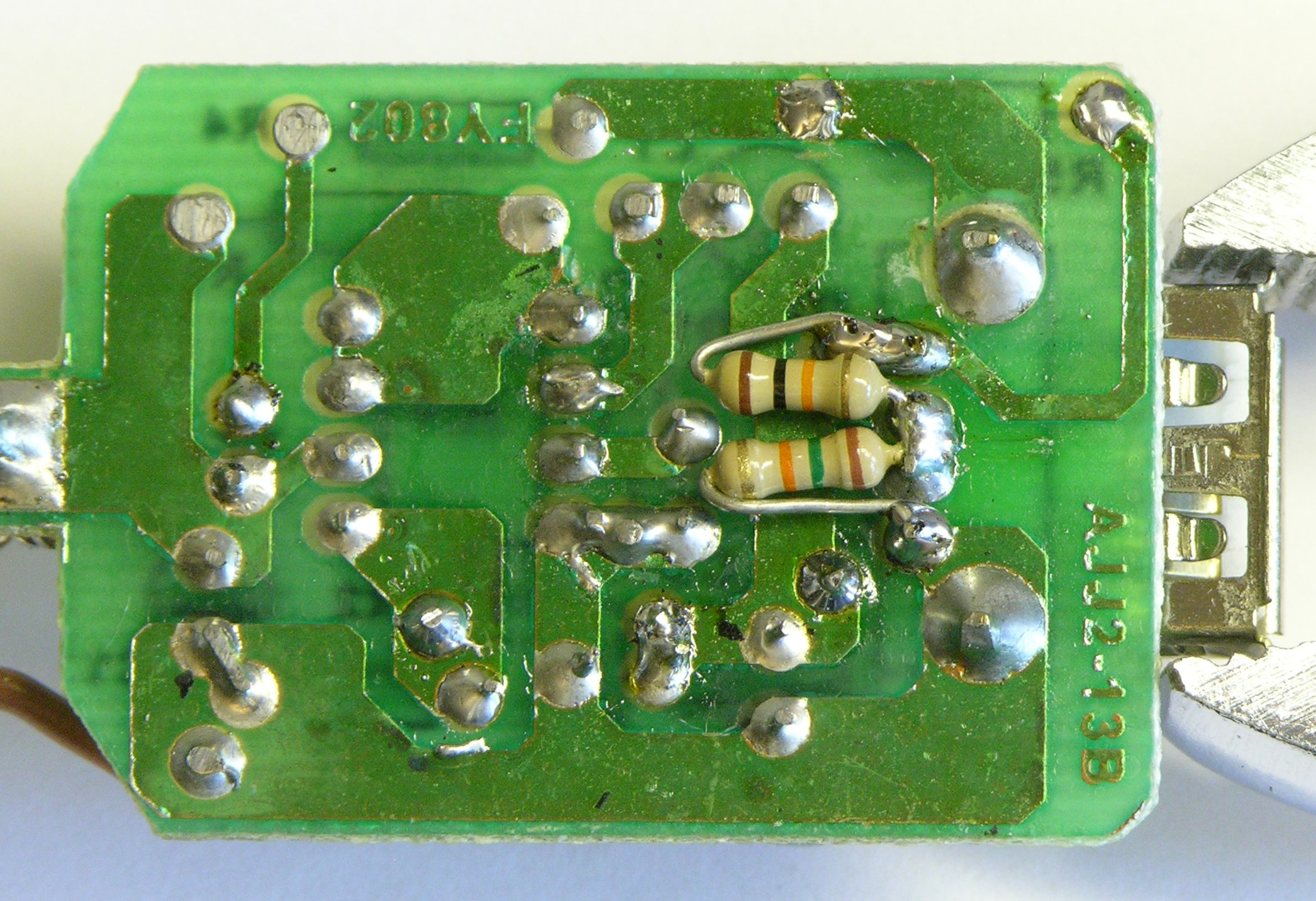
Having found the IC datasheet, the next order of business was creating a schematic of my power adapter. I examined the PCB and positioned all the components in EAGLE, substituting a couple of four-pin connectors for the IC that doesn’t exist in my library. After verifying I had captured all the connections, I rearranged the components on the schematic from their positions on the PCB to this more logical placement.
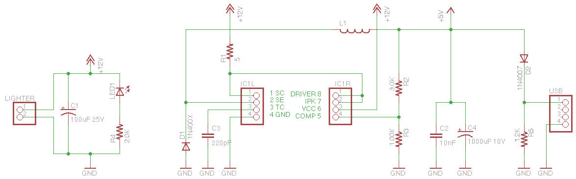
While I was working on that, Cort had hooked up the adapter to his bench power supply and fed it 12-13V. He measured the output and got about 4.64V with no load around the same time I was finding that R2 = 3.0KΩ and R3 = 1.00KΩ, programming the circuit for 5.0V operation.
The issue is that the series diode D2 drops the output voltage by somewhere in the .6V – .8V range (from the 1N4007 datasheet, in the no-load to 200mA load range); and Cort measured 5.29V – 5.30V at D2′s anode.
Grrrrreat! We’re calling this a 5V output, but due to the protection diode, feeding the output scarcely over 4.6V, and thinking that devices expecting 5V will charge on it!
Works Fine with No Output Protection
The first thing we did was pull D2 and replace it with a jumper wire. No D2, no voltage drop. 5.30V output. Great!
But then my conscience got the better of me. D2 is obviously there to protect the DC-DC converter from a higher voltage where it’s expecting a load; and although I don’t intend to connect such a thing, who knows what may happen.
Change the Voltage Divider?
| Original | Change R3 | Change R2 | Change Both | |||
|---|---|---|---|---|---|---|
| R2 | 1000 | 1000 | 850 | 1200 | 935 | 1134 |
| R3 | 3000 | 3528 | 3000 | 4234 | 3300 | 4000 |
| V(REG) | 5 | 5.66 | 5.66 | 5.66 | 5.66 | 5.66 |
| V(OUT) | 4.34 | 5 | 5 | 5 | 5 | 5 |
| V(D1) | 0.66 | |||||
My next thought was to change the resistor values to regulate the voltage to 5.66V so the post-diode output would be 5V. I made a spreadsheet and played around with substitutions for R2 and R3 but didn’t come up with any combination I loved using standard values.
Diode in voltage regulation circuit
Finally I had a better idea, the one we stuck with. We inserted a diode (a small-signal diode ’cause it was easier to fit in place) between the regulated voltage and the top of the voltage divider. It drops .6V – .7V from the regulated voltage before it gets sampled for the feedback circuit, so the voltage is regulated to about 5.6V – 5.7V, then D2 takes its .6V – .7V, and we get about 5.0V – 5.1V at the output like we oughtta.
| Configuration | Load (Est) | Voltage |
|---|---|---|
| Internal 1.2KΩ drain | 4.4mA | 5.25V |
| 560Ω | 14mA | 5.21V |
| 2x 120Ω | 90mA | 5.13V |
| 3x 120Ω | 132mA | 5.11V |
| 5x 120Ω | 216mA | 5.09V |
| 6x 120Ω | 258mA | 5.08V |
| 15Ω | 342mA | 5.07V |
| 10Ω | 508mA | 5.04V |
| 8Ω | 549mA | 4.36V |
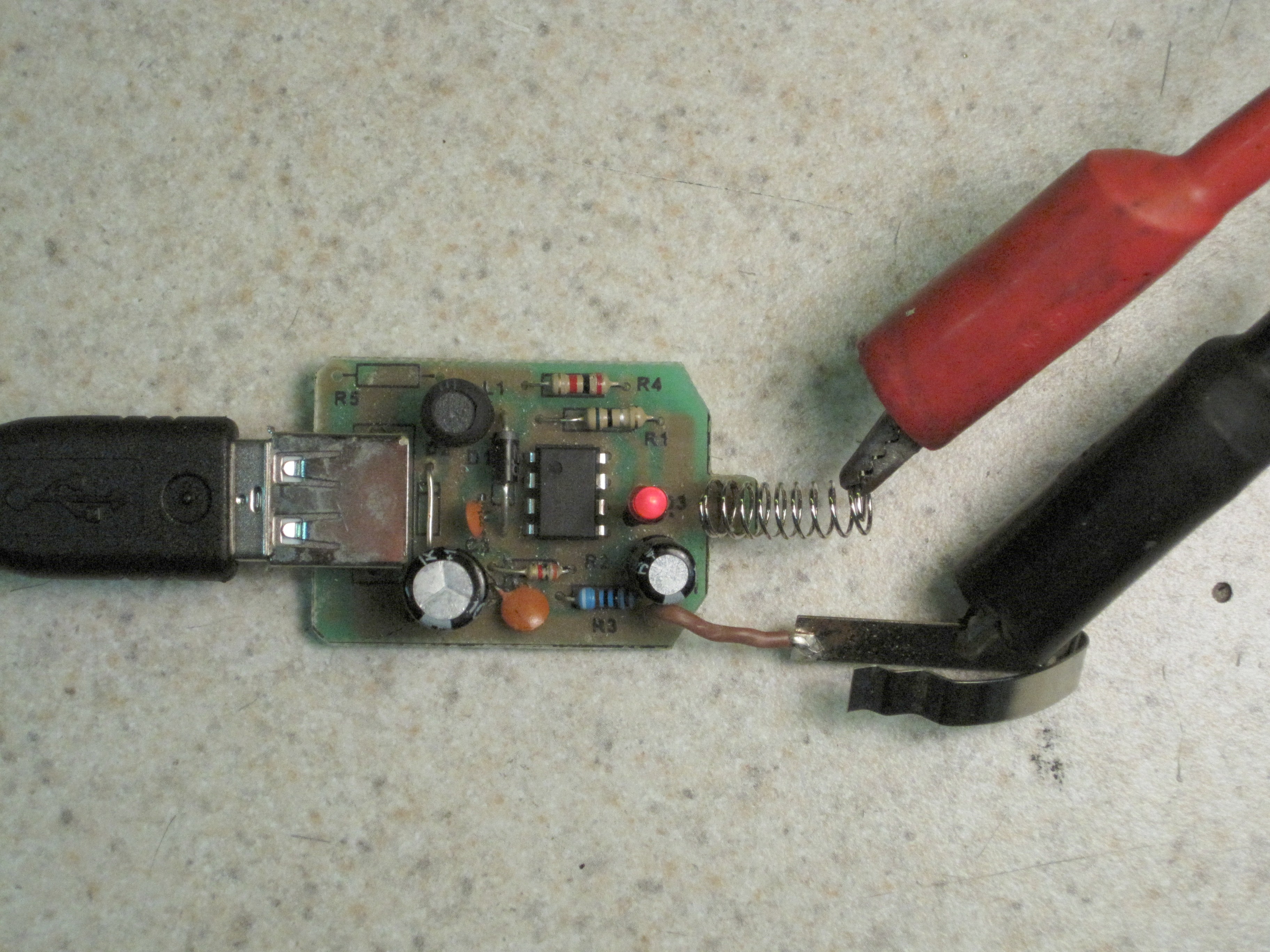
We were curious about the accuracy of its regulation, so Cort grabbed a resistor, hooked it up to the outputs with gator wires, and measured the output voltage. It was a bit high but the load was very light, so we tried a lower-valued resistor to increase the load. Then two, then more, and more, and more; and by the time we got to the 8Ω sand resistor we were giddy and cackling for no reason I can figure out in retrospect.
Looks like it has pretty good regulation up to about 500mA load, and we haven’t even monkeyed with RSC yet. That should be plenty good to charge my phone.
The Trial
I drove two and a half hours home with my phone plugged in all the way. I deliberately didn’t fully charge it the night before, so I started the trip with half a charge and ended with no charge.
You gotta be kidding me.
USB Power Negotiation
I’m familiar with the formal power negotiation a device is supposed to do with a USB hub (using a maximum of 100mA unless it negotiates more), but I also know that most devices can charge from power sources I’m pretty sure don’t have full-fledged negotiation in them. And I started thinking about Adafruit’s great writeup of charging iPhones with a MintyBoost.
The bottom line is that iPhones want the USB data lines strapped to certain voltages to tell them “I’m not really USB but I’ll give you power.” Not only that, but in later iPhones, different voltages inform the device of different amounts of current it’s allowed to draw.
I was back at Cort’s house Wednesday night and mentioned that I wanted the data lines strapped to 3.3V. He asked whether I wanted him to fix my power adapter while I finished proofreading my conference presentation for Thursday, and we had a deal.
Looks like he used 10KΩ and 15KΩ on the 5Vish output to give me 3V on the data lines. We weren’t sure whether we needed a separate voltage divider on each data line like the MintyBoost uses, but when we plugged in my Blackberry the current draw (as registered by the power supply) jumped from 72mA to 290mA.
I’d forgotten my USB charging cable at home so didn’t get a chance to charge the Blackberry on the return trip, but the huge increased draw on the adapter’s supply side is a pretty good sign that I’m really finally charging.
Nice writeup & explanation of debugging a circuit like this…but personally I would have just bought another $1.99 adaptor
Good writeup! Well done. I’m glad you looked into it. Unlike David R, I would have been concerned that another device would have the same problems.
That is a classic chip, originally from Motorola, now On semi –
http://www.onsemi.com/PowerSolutions/product.do?id=MC33063A. Many people make an equivalent.
Dave jones has a great video using it,
http://www.eevblog.com/2010/09/10/eevblog-110-lets-design-a-dc-to-dc-switchmode-converter/
Brilliant! I’ve got a couple of these that don’t charge things properly, so it’d be great to fix them. Thanks for the information.
shouldn’t you just shorted the data pins? that’s how dumb devices are supposed to tell usb devices that they are not a usb host.
anything less than 1kOhm does the trick, according to specs.
Gabriel, read Adafruit’s article to which I linked. Shorting data pins isn’t sufficient for today’s devices.