Speaker Power Detector Part 3: Layout and Prototype
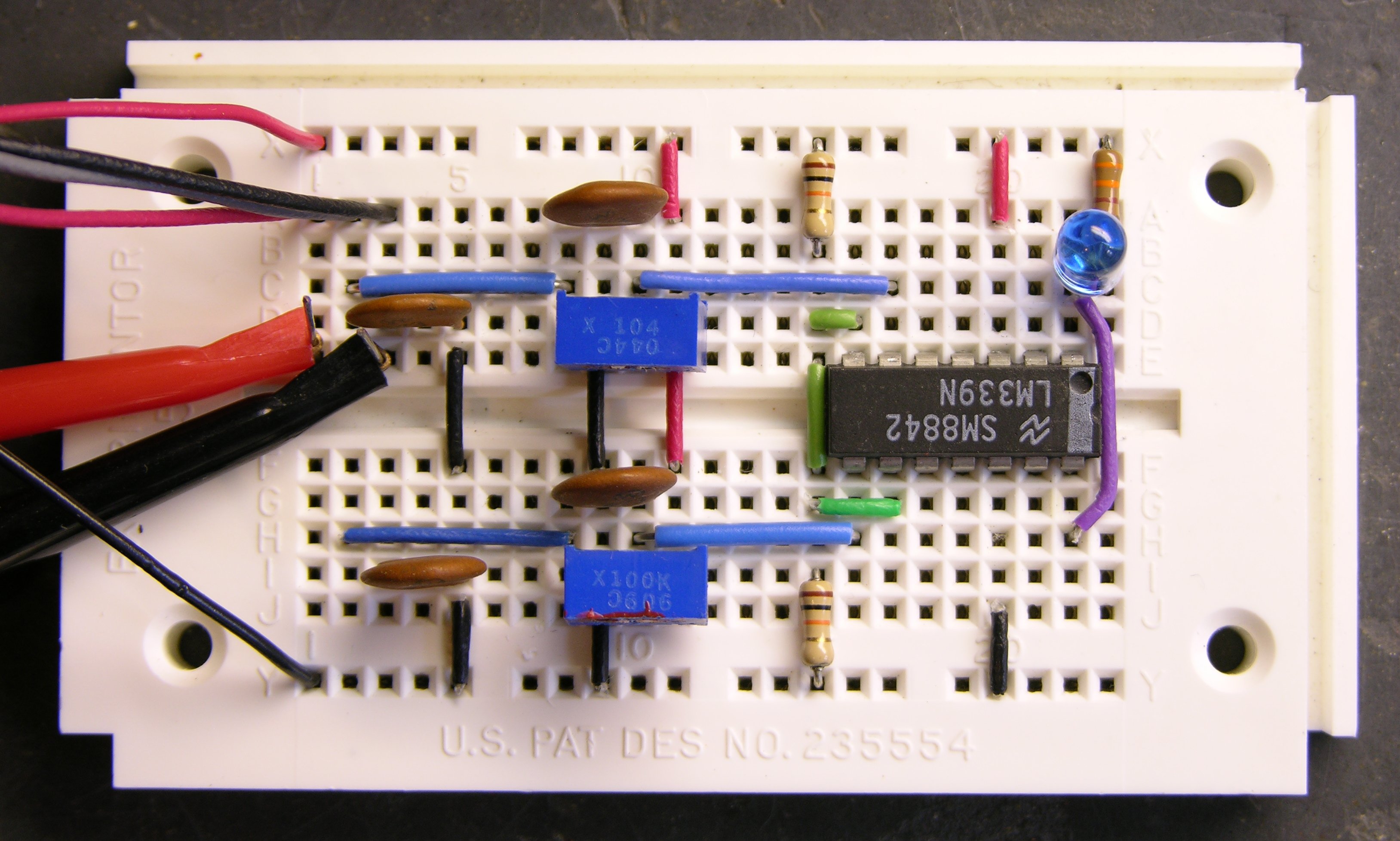
Here’s my prototype of the circuit on a solderless breadboard:
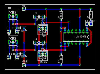
And here’s the board layout.
A few notes:
- The blue traces represent the connections that are already built into the breadboard. The red connections are wires plugged in on the top.
- The LM339 goes upside-down from the normal orientation, with the dimple or dot at the right end.
- My speaker potentiometer is connected via wires, not mounted directly to the board as shown in the layout. Yours can be, too
- I connected a speaker-like signal with the clips at the left of my breadboard. Yours would be wired to the speaker jacks.
- I didn’t install the right speaker input and potentiometer on my prototype, so there’s a gap in the lower left where they’d go.
With those few issues in mind, this should give you enough information to assemble your own.
Part 0: Project Overview
Part 1: Schematic and Operation
Part 2: Parts and Enclosure
Part 3: Layout and Prototype
Part 4: Construction and Calibration
My blog software doesn’t allow comments on “pages” (like this); so if you have feedback, please go to my related post and add a comment.