Speaker Power Detector Part 1: Schematic and Operation
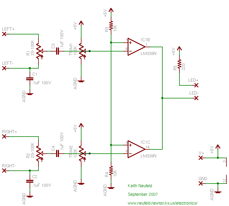
Here’s the schematic. If you’re interested in following along about how this works, you should view the image in a separate window (it’s scaled down a bit here) and optionally print a copy for reference.
Comparator
The circuit revolves around the LM339, a low-power comparator designed to be easy to operate from a single (positive) power supply. A comparator compares two voltages and outputs a high, positive voltage if the first input (“non-inverting,” marked with a +) is higher or a zero or negative voltage if the second input (“inverting,” marked with a -) is higher. The circuit design then becomes pretty clear — just some connecting parts to hook the speaker wires up to the LM339 and see whether there’s a signal on them larger than some preset threshold.
The overall circuit is two duplicated comparator sections for the left and right speaker channels, with open-collector outputs tied together to logically “OR” them (active low), to turn on the LED if a signal is seen on the left or right channel.
Starting with the main comparators (IC1B and IC1C) and working backward:
Strung vertically across the middle of the circuit, resistors R3 and R4 divide the supply voltage in half to provide a reference against which to compare the input signal. The reference voltage is connected to the comparator’s non-inverting inputs; so the output will be high if the reference voltage is higher and low if the speaker signal voltage is higher.
Bias and Capacitor-Coupling
The 100K trimmer potentiometer provides a bias voltage for the capacitor-coupled speaker input. In an amplifier or comparator circuit with a single supply voltage, the input is typically connected with a capacitor to ignore (block) the absolute (DC) voltage value and look at (pass) only the changing (AC) portion of the signal. The bias voltage thus provides a baseline (set slightly lower than the reference voltage) to which a fraction of the speaker voltage is added.
Potentiometers R1 and R2 deliver a portion of the speakers’ signal into the circuit. A power amplifier putting out 200W RMS into an 8Ω speaker is running 40V RMS or 57V peak. Although the LM339 is pretty rugged and can take input voltages higher than its supply, it’s not rated for inputs that high. The potentiometer allows us to extract a portion of the total speaker voltage, and to choose on the fly how much of it we want.
Ground Coupling
Capacitors C1 and C2 are a bit unusual, and I’m not altogether happy having them there, but I don’t see how to get around it. If this circuit were built as part of a larger project or product, inside the same case, I wouldn’t have need for them — the speakers’ – (ground) connections could tie directly to this circuit’s ground.
But what if someone reversed the speaker wires, or has an amplifier with push-pull outputs and the black wire is hot with opposite polarity, or has an amplifier with a phase-inverting button and presses it accidentally? If the right and left speakers’ black wires were tied together inside the power detector circuit, and if they were ever connected to anything other than ground, they’d likely destroy the power amp’s output transistors. Rather than chance that happening, I capacitor-coupled the speakers’ negative terminals as well.
Since capacitors pass AC, real audio signals will probably go right through them and short the amplifier anyway. The ground capacitors should probably be replaced with small fuses, to deliberately blow out before the amplifier. Maybe a 100KΩ resistor, actually? I’ll play with this some more, and I’m open to suggestions.
Comparator Summary
When the amplifiers are delivering a signal to the speakers that are wired into the power detector, a varying voltage appears across the LEFT+ / LEFT- and RIGHT+ / RIGHT- terminals. A portion of the voltage is “extracted” by potentiometers R1 and R2, and the varying (AC) component of this voltage is passed through capacitors C3 and C4 to be added to the baseline (bias) voltages set by TRIM1 and TRIM2.
With no signal present at the comparator’s inverting (-) inputs, its outputs are high. When the sum of the varying speaker voltage plus the bias voltage, delivered to the inverting inputs, is higher than the reference voltage (formed by R3 and R4) at the non-inverting inputs, then the comparator’s outputs go low.
OR Logic and LED Output
The LM339′s outputs are open-collector, meaning that they don’t actually actively drive the output high. When their output should be logically high, they actually do nothing to the output, letting it be whatever it wants. When their output should be logically low, then they actively pull the output level down to ground.
This may sound inconvenient; why wouldn’t they actively make their output high? Well, I said that when the output should be logically high, they actually let it be whatever it wants — and R5 tied from the output through the LED to the 5V power supply makes the output want to be 5V. When the output should be low, as I said, the comparator will pull the output low.
This permits us to tie together the outputs of many comparator gates and detect when any one (or more) is low. Any gate with a logically low output actually pulls the output low. Any gate with a logically high output leaves the output line alone. So if all the comparator outputs are logically high, R5 will pull the output line up to 5V. If any one (or more) output is low, it pulls the output line down to 0V.
When there’s no speaker signal, both comparator outputs are logically high and floating, the common output line is high, there’s no power across the LED, and it’s dark. When one or more speakers has a signal, its comparator output is low, there’s power across the LED (5V on the top and 0V at the comparator end), and it lights.
Part 0: Project Overview
Part 1: Schematic and Operation
Part 2: Parts and Enclosure
Part 3: Layout and Prototype
Part 4: Construction and Calibration
My blog software doesn’t allow comments on “pages” (like this); so if you have feedback, please go to my related post and add a comment.