I’m wanting to play with a medium-resolution LCD screen attached to something that I can program from the Arduino IDE and I happen to have some “AITRIP”-branded ESP-WROOM-32 modules on hand. Connecting an ST7789-driven LCD to one of them involved filling in a number of gaps in the documentation I was able to find, so let me write it all down in one place in case it’s useful to someone else, including Future Keith.
The LCD I bought is a Waveshare 2.0″ LCD using an ST7789V driver chip, a variant of a popular (the popular?) LCD driver.
Wiring
The first puzzle was how to wire the LCD to the ESP32.
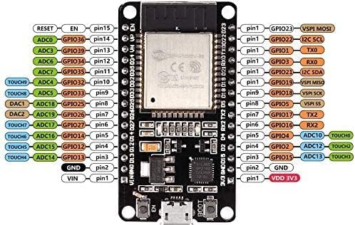
Different ESP32 module manufacturers provide different module pin counts and I suspect (though haven’t verified) different pinouts for the same pin counts; so I’m specifically referencing the pinouts for the module I’m using.
I found a couple of forum posts — unfortunately didn’t save the links — indicating that the LCD can run on 5V or 3.3V power and that it gets grumpy if the data lines are at a different voltage than its power. This is easily handled — power the LCD from the ESP32′s 3.3V regulator. So first wire the power connections:
| LCD Pin | ESP32 Pin | Signal |
|---|---|---|
| VCC | VDD 3V3 | 3.3V regulated power |
| GND | GND | ground |
Next, the LCD uses SPI, so wire the data and clock lines. The ESP32 has labeled pins for these so I used them; though I saw a forum post that the ESP32′s hardware SPI can be matrixed to any digital I/O pin, so it’s possible that these could be reassigned elsewhere.
| LCD Pin | ESP32 Pin | Signal |
|---|---|---|
| DIN | VSPI MOSI aka GPIO 23 | SPI master out / slave in aka PICO (peripheral in / controller out) |
| CLK | VSPI SCK aka GPIO 18 | SPI clock |
Then three LCD pins can be wired to any available I/O, so I picked pins near the others I was already using:
| LCD Pin | ESP32 Pin | Signal |
|---|---|---|
| CS | GPIO 1 | SPI chip select |
| DC | GPIO 3 | LCD data / command select |
| RST | GPIO 21 | LCD module reset |
And finally the backlight enable pin, which the schematic shows is pulled high / active so is superfluous unless you want to blank or PWM the backlight:
| LCD Pin | ESP32 Pin | Signal |
|---|---|---|
| BL | GPIO 17 | backlight control (active high) |
Arduino Libraries
Waveshare provides their own ST7789 and LCD graphics libraries but I overlooked those, so for what seemed like expedience I loaded the Adafruit ST77* library and Adafruit GFX library.
I could not find, in the documentation or tutorials, the syntax for some fundamentals — to wit, I didn’t find documentation stating the syntax to instantiate a display object, nor documentation of (the correct) syntax to initialize the display object. (I ran across what in retrospect incidentally sort of demonstrated these; but I would like documentation to expressly tell me how to use what I’m trying to use.)
The libraries come with example code and by examining Examples from Custom Libraries / Adafruit ST7735 and ST7789 Library / graphicstest_st7789, and with the help of a forum post, I was able first to get the graphics demo to run on my display and second to write my own code.
The library needs to know where things got wired up:
#define TFT_CS (1)    //  yellow wire

#define TFT_RST (21)  //  brown wire

#define TFT_DC (3)    //  blue wire
Then to be initialized with the right dimensions for this LCD:
  // OR use this initializer (uncomment) if using a 2.0" 320x240 TFT:

  tft.init(240, 320);           // Init ST7789 320x240
And then the demo works.
My Demo
Putting it all together into my own test:
#include <Adafruit_GFX.h>

#include <Adafruit_ST7789.h>
#define TFT_CS (1) // yellow wire
#define TFT_RST (21) // brown wire
#define TFT_DC (3) // blue wire
#define PIN_BACKLIGHT (17) // grey wire
Adafruit_ST7789 mylcd = Adafruit_ST7789(TFT_CS, TFT_DC, TFT_RST);
void setup() {
pinMode(PIN_BACKLIGHT, OUTPUT);
digitalWrite(PIN_BACKLIGHT, HIGH);
mylcd.init(240, 320);
mylcd.setRotation(1);
mylcd.fillScreen(ST77XX_BLACK);
//mylcd.drawLine(0, 0, 25, 25, 65535);
mylcd.setCursor(0, 0);
mylcd.setTextColor(65535);
mylcd.setTextSize(3);
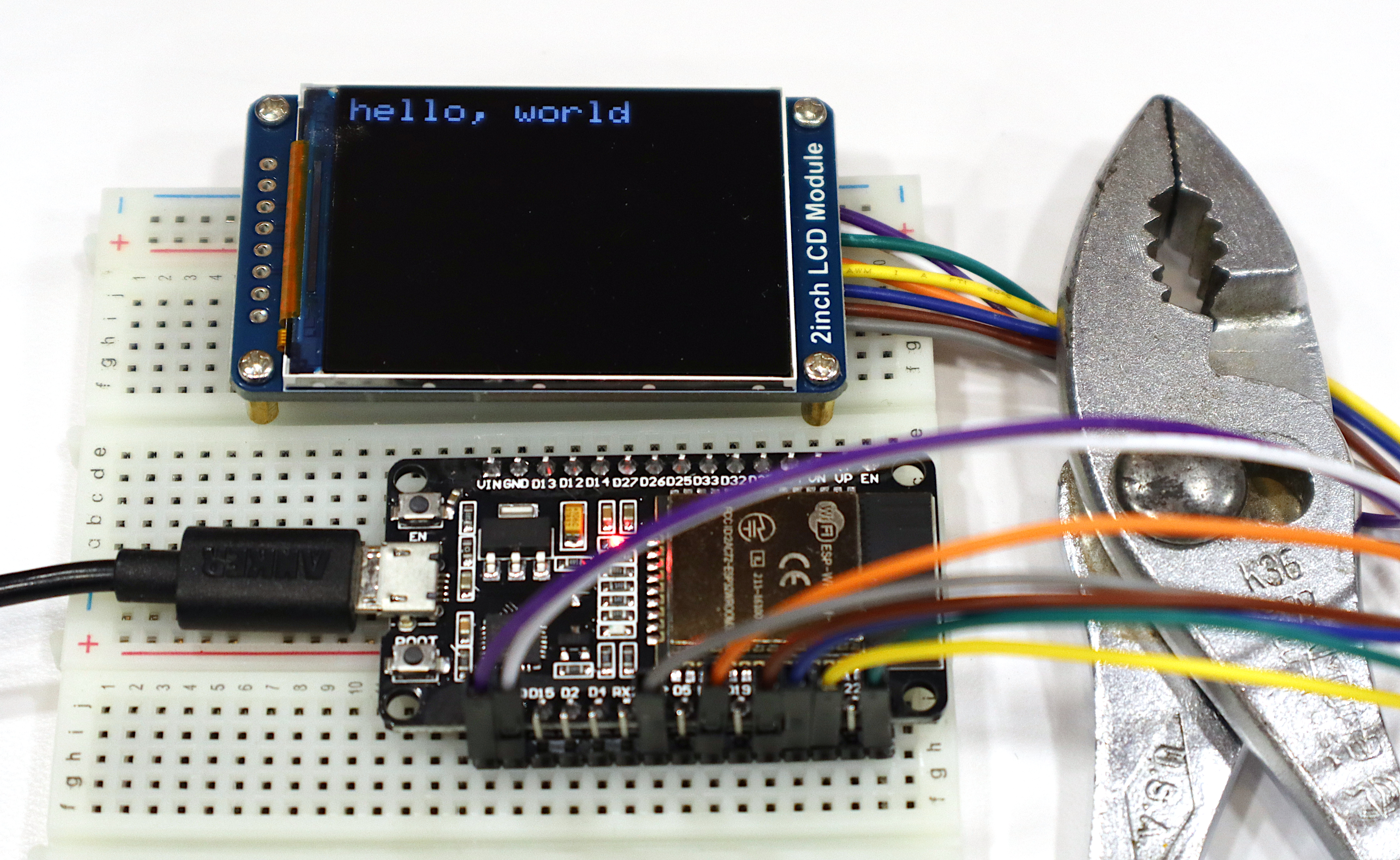
mylcd.print("hello, world");
}
void loop() {
}